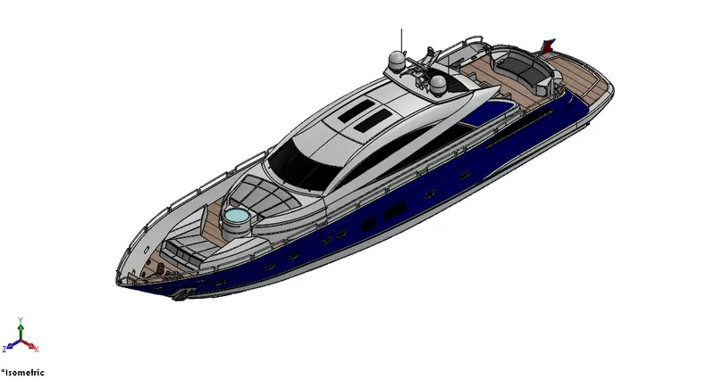
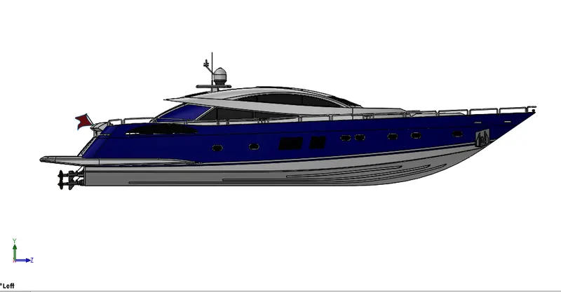
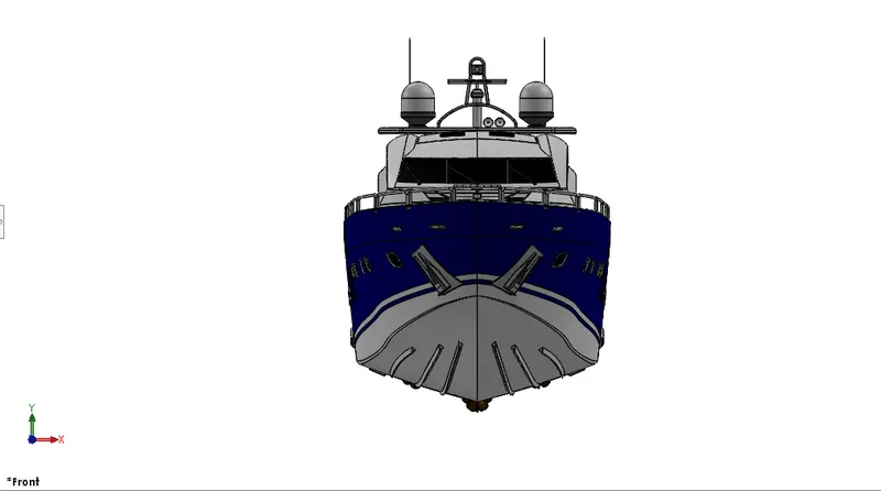
Radar Mast & Final Assembly of Yacht
MODELLING OF
YACHT
ON
SOLIDWORKS
INTRODUCTION:
In this project we learn about the design of YACHT
assembly with help of SOLIDWORKS. In this we first
learn to use the commands and then we draw parts. By
using blueprint sketch, we get idea of sketching the parts
and its dimensions. After designing all the parts we do
assembly of yacht . After assembly we add decals,
lights, camera and do rendering of yacht by using
SOLIDWORK visualization.
The components which we learnt in yacht are:
1.Propeller
2.Garage door
3.Front seat
4.Middle seat
5.Rear seat
6.Hull
7.Radar
8.Radar mast
9.Superstructure
10.Blueprint setup
OBJECTIVE:
- To learn the feature and surface commands of
SOLIDWORKS in depth. - To know about the sketch tools , planes in
SOLIDWORKS. - By using blueprint setup we can design all the parts
of yacht very easily. - Assembling all the parts in SOLIDWORK.
- We can learn how to apply appearances to parts.
- Get the knowledge of concepts like decals, light and
camera angle. - Proper setting of image quality and getting realistic
view with the help of PHOTOVIEW 360. - Rendering of YACHT has done with help of
SOLIDWORKS visualization software.
DESIGN APPROCH:
There are two types of approach in design procedure
1.Bottom up approach
2.Top down approach
Bottom up approach: The design approach in
which the most primary operations are specified
first then combined it later to make larger
progressive unit .Here in this project we have
used bottom up approach procedure.
Top down approach: Top down assembly
modelling is an assembly-centric modelling
method where the assembly design is started at
the highest level possible , and individual parts
and subassemblies are defined within the
context of the overall assembly.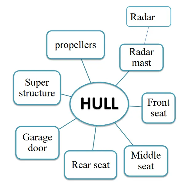
The features , tools , properties used in the design of
components and the entire model are:
1.boss extrude
2.Extrude cut
3.Fillet
4.Chamfer
5. Boss revolve
6.Shell
7.Mirror
8.Reference geometry
9.Projected curve
10.Knit surface
11.Extrude surface
12.Sweep surface
13.Lofted surface
14.Ruled surface
15.Filled surface
16.Trim surface
17.Split line
18.Offset surface
19.Extend surface
20.mates
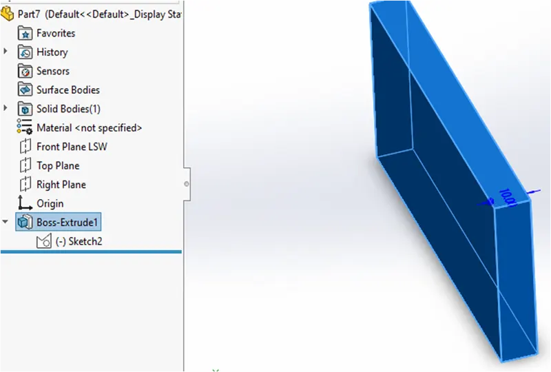
Boss Extrude :
This is a basic feature of SOLIDWORKS. The boss
extrude feature will project a 3D model with the help
of selected 2D sketch . For this first we have to select
a plane ,sketch on it and exit the sketch and select
boss extrude in the feature tab and give parameters
according to our need . Basically boss extrude extend
a sketched profile in one or two directions as either a
thin feature or a solid feature.
Example:
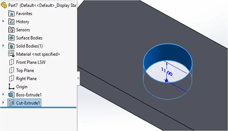
Extrude cut:
As the name includes cut , means it removes the
material from the part . You can create extruded cut in
one or two directions depends on our need by using
the 2d sketch we have drawn . Steps to create cut
extrude are first we have to draw a 2d sketch using
sketch tools and then by exiting the sketch and going
to features tab and selecting extrude cut and giving
parameters we can complete this extrude cut .
Example view of extrude cut is:
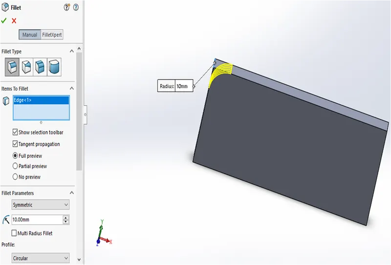
Fillet:
Fillet creates a rounded internal or external face on
the part . You can fillet all edges of a face , selected
sets of faces , selected edges .on the feature tab
select fillet and then give parameters like on which
edge or face we have to do fillet all then say ok to
create a fillet.
Example:
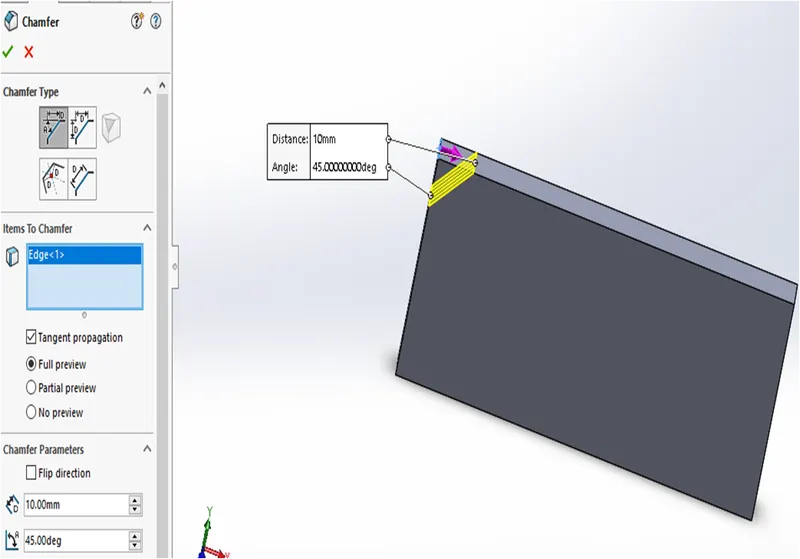
Chamfer:
The chamfer tool creates a beveled feature on
selected edges , faces , vertex .
To create a chamfer:
1. Select chamfer on features tab
2. Give parameters like which type of chamfer
(angle-distance or distance-distance)and all.
3. Click ok.
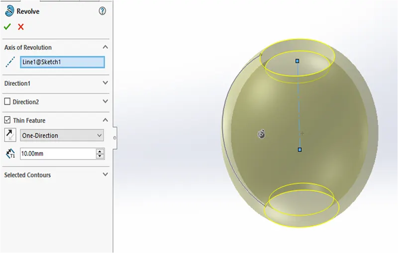
Boss revolve:
Revolves add or remove material by revolving one
or more profiles around a centerline. You can
create revolved boss/bases, revolved cuts, or
revolved surfaces. The revolve feature can be a
solid, a thin feature, or a surface. To create revolve
boss extrude draw a 2d sketch using sketch tools
and then exit the sketch and select the revolve boss
in feature tab and then select the revolve axis and
give parameters and say ok.
Example :
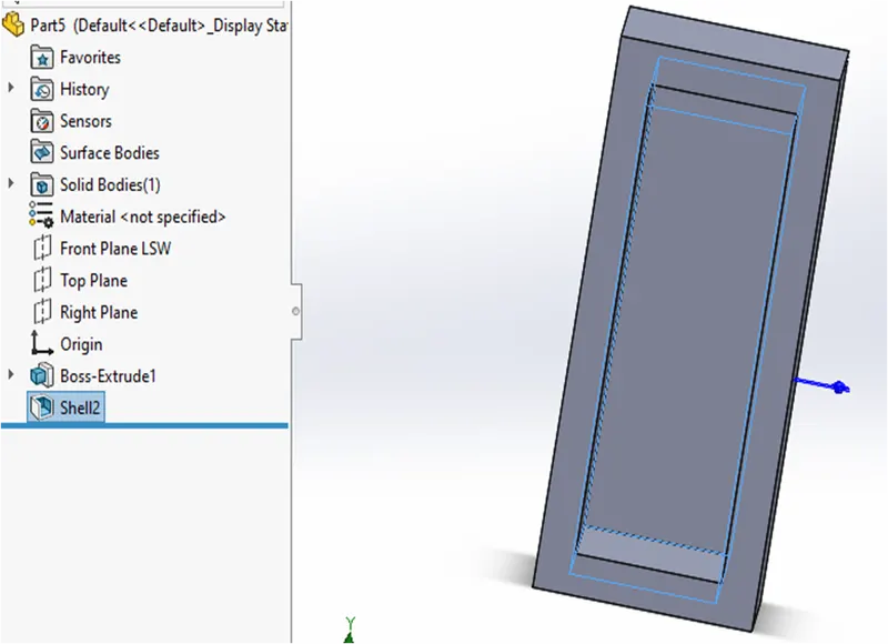
Shell:
It is very handy tool in SOLIDWORKS . It gives
some sort of idea that how inside geometry of a part
will appear . In this tool we give inside thickness to
the geometry and material removed from the body
and it becomes hollow.
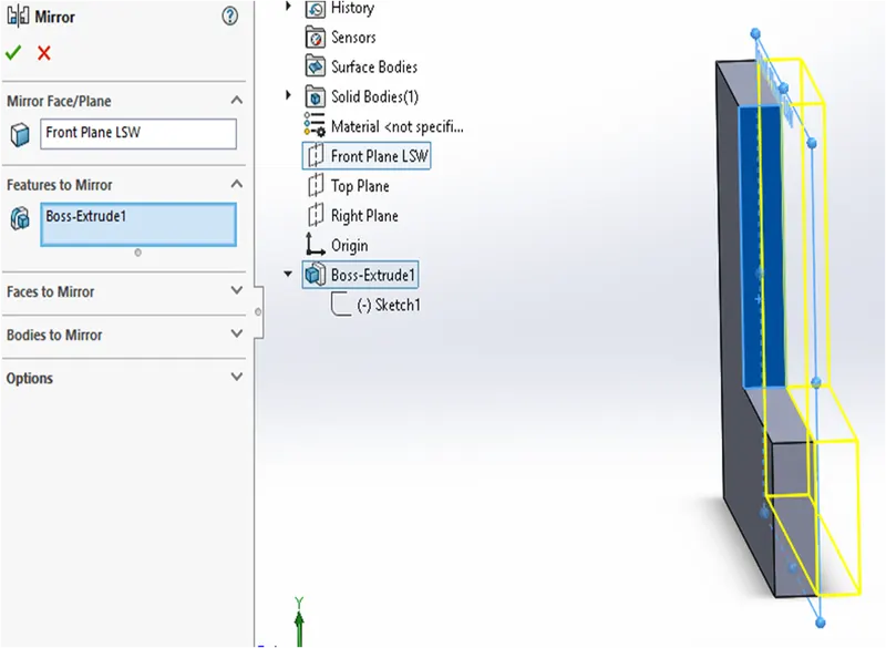
Mirror:
Mirror copies the selected features or all features,
mirroring them about the selected plane or face.
When this feature is applied it need plane or axis to
mirror . Select the body which is to be mirror ,
select an axis or plane then apply feature and the
mirrored part will get .
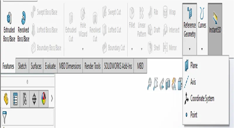
Reference geometry:
Reference geometry defines the shape or form of a
surface or a solid. Reference geometry includes
items such as planes, axes, coordinate systems, and
points . You can use reference geometry in the
creation of several kinds of features.
For example :
Planes are used in lofts and sweeps.
An axis is used in a circular pattern.
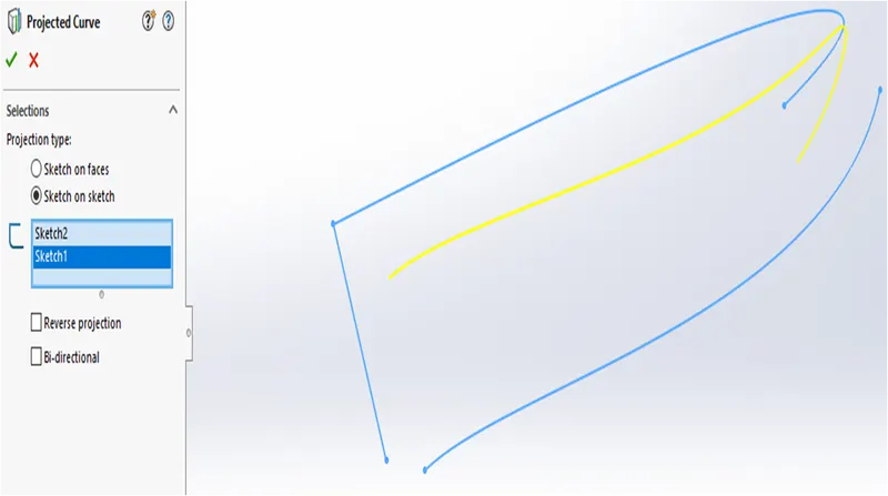
Projected curve:
You can project a sketched curve onto a model face to
create a 3D curve. You can also create a 3D curve that
represents the intersection of two extruded surfaces
generated by creating sketches on two intersecting
planes.
You can create multiple closed or open-contour
projected curves from a single sketch. You can also
use 3D sketches as input for the Projected Curve tool.
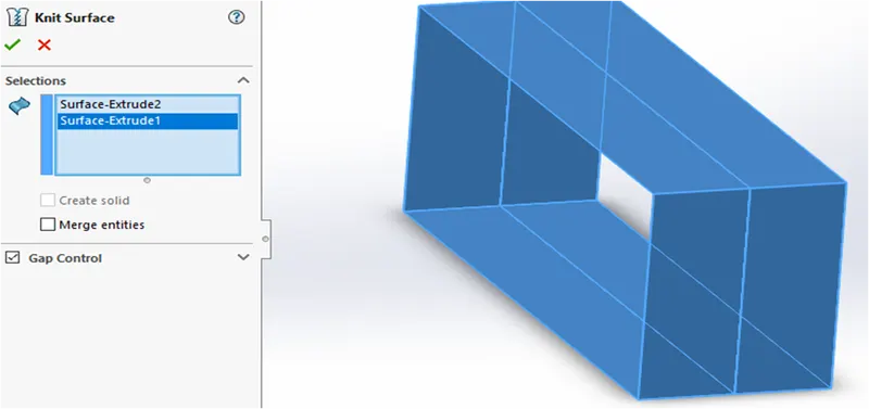
Knit surface:
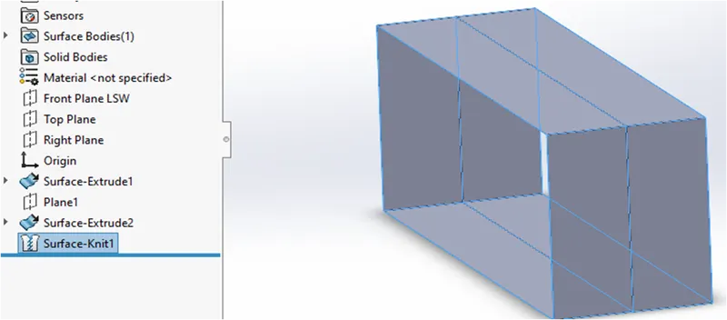
Use of knit surface tool to combine two or more
faces and surfaces into one . It creates a solid body
when the knit surfaces form a closed volume or
leaves as a surface body.
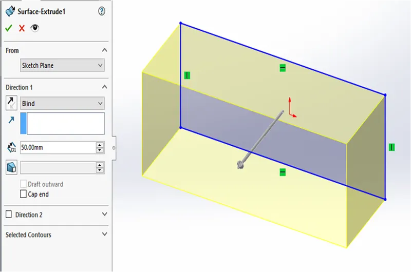
Extrude surface:
You can create extruded surfaces from models that
include 2D or 3D faces. Using the SOLIDWORKS
Surface Extrude feature, we can extrude the
boundary edges of a face of a solid body or edges of
a surface body in a customized direction.
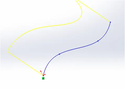
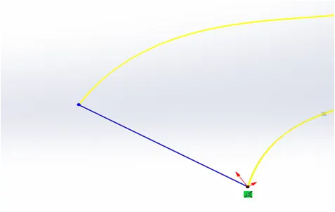
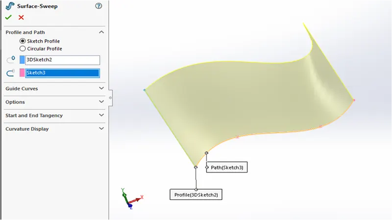
Sweep surface:
Sweep Surfaces are surfaces that are generated from a
section curve positioned along a path.
For every surface sweep there should be a profile and
its path for example:
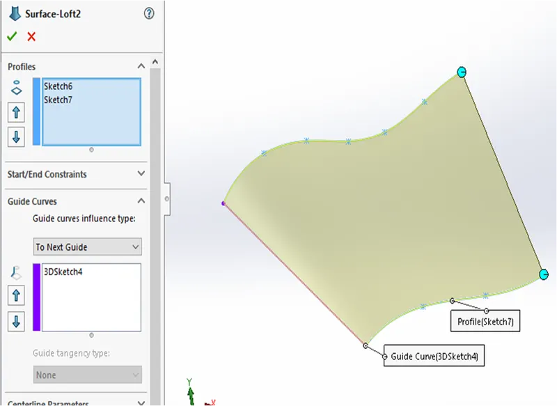
Lofted surface:
Loft Surfaces are surfaces generated by multiple 3D
Curves or existing edges creating a smooth tangency
between the selected curves.
Example:
Ruled surface:
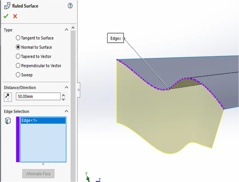
The Ruled Surface command creates surfaces that
extend out in a specified direction from selected
edges. Examples of how you can use ruled surfaces:
Add tangent extensions to complex surfaces. Create
drafted sidewalls.
Example:
Filled surface:
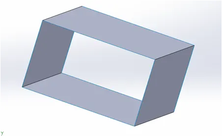
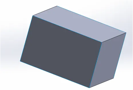
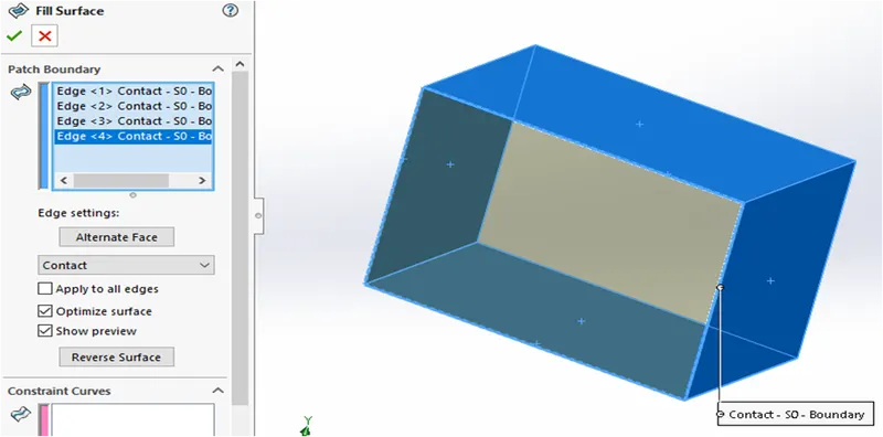
The Filled Surface feature constructs a surface patch with
any number of sides, within a boundary defined by
existing model edges, sketches, or curves, including
composite curves. You can use this feature to construct a
surface to fill a gap in a model.
Example
BEFORE AFTER
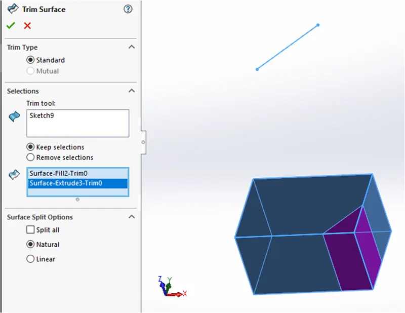
Trim surface:
You can use a surface, plane, or sketch as a trim tool
to trim intersecting surfaces. Create two or more
surfaces that intersect at one or more points, or
create a surface that intersects with a plane or has a
sketch on its face.
Click Trim Surface on the Surfaces toolbar, or
click Insert > Surface > Trim.
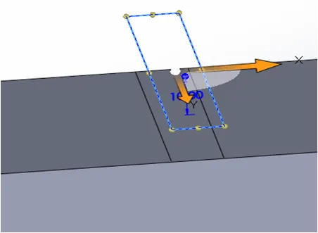
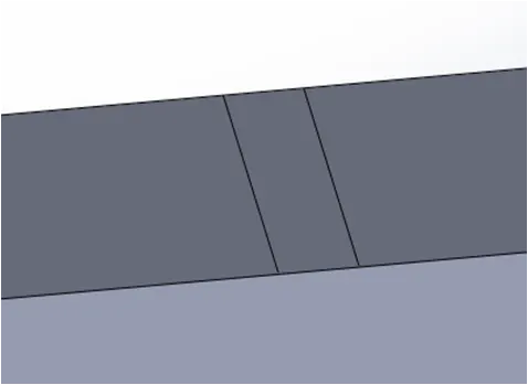
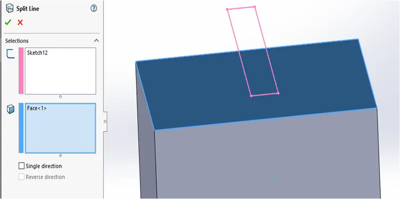
Split line:
The Split Line. tool projects an entity (sketch, solid,
surface, face, plane, or surface spline) to surfaces, or
curved or planar faces. It divides a selected face into
multiple separate faces.
Example:
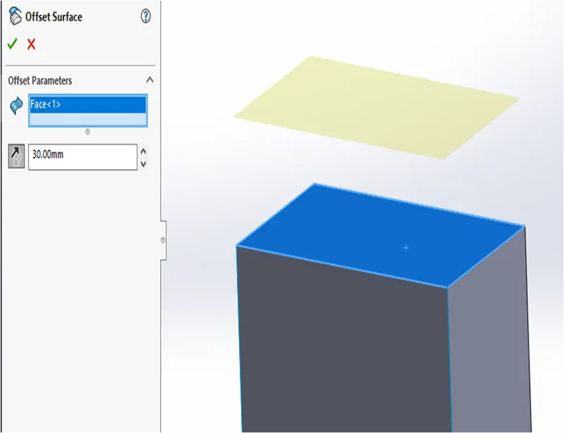
Offset surface:
The Offset Surface tool creates a new surface body
from an existing set of faces . You can create an
offset surface with a distance of zero.
Example:
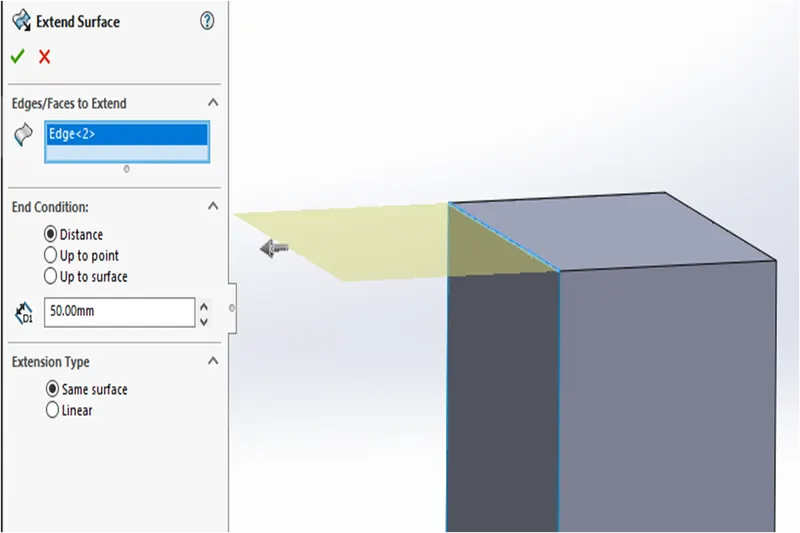
Extend surface:
You can extend a surface by selecting an edge,
multiple edges, or a face. For edges, the surface
extends along the plane of the edge. ... For faces,
the surface extends along all edges of the face
except those connected to another face.
Example:
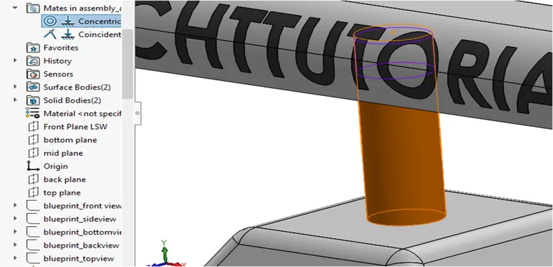
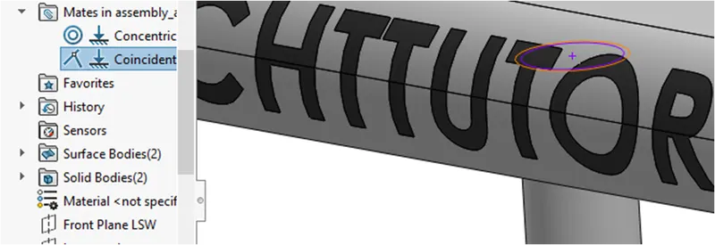
Mates:
Mates create geometric relationships, such as
coincident , perpendicular , tangent , and so on
between assembly components. As you add mates, you
define the allowable directions of linear or rotational
motion of the components. You can move a component
within its degrees of freedom, visualizing the
assembly's behavior.
Sketch:
When you open a new part document, first you create a
sketch. The sketch is the basis for a 3D model. You can
create a sketch on any of the default planes (Front
Plane, Top Plane, and Right Plane), or a created plane.
You can start by selecting :
Sketch entity tools (line, circle, and so on)
Sketch tool (entities etc…)
Planes
Extruded Boss/Base or Revolved Boss/Base on the
Features toolbar.
You can also create a sketch on a flat surface, a
spline on a surface, or the face of a solid.
Now we completed discussion of how the
features work under SOLIDWORKS . let us
see the application of the features in the
YACHT that we have built. We are going to
discuss part by part as shown in the flowchart.
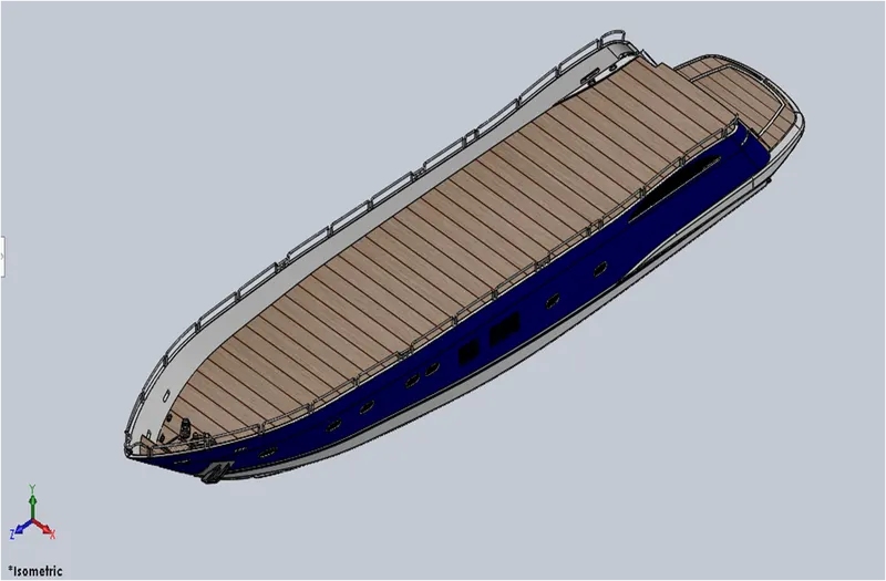
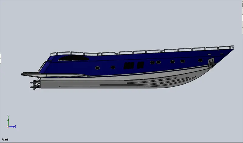
Hull:
Hull is the major part in the design of yacht. A hull
is the watertight body of a ship, boat, or flying boat.
The hull may open at the top (such as a dinghy), or
it may be fully or partially covered with a deck.
Atop the deck may be a deckhouse and other
superstructures, such as a funnel, derrick, or mast.
The tools used to create hull are:
1.Surface loft
2.Surface trim
3.Surface and boss extrude
4.Projected curves
5.Reference geometry
6.Knit
7.Fill surface
8.Fillet
9.Chamfer
10.Cut extrude
11.Sweep
12.Mirror
13.Split line
Propeller:
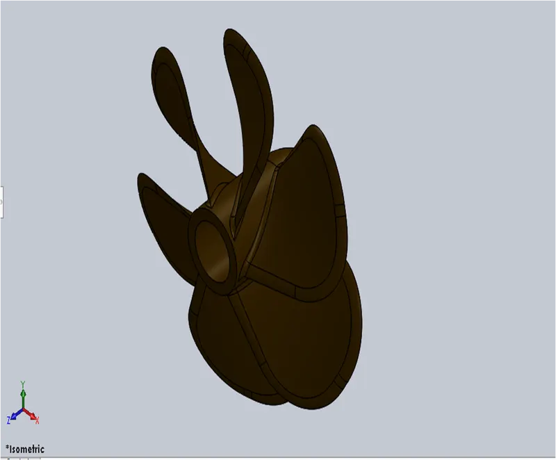
Propellers are used to pump fluid through a pipe
or duct, or to create thrust to propel a boat through
water or an aircraft through air. Here we have
inserted 3 propellers to the hull . And the
appearance given to propellers is dark brown type
colour .
Features used to create propellers are:
1.Revolve
2.Reference geometry
3.Loft
4.Fillet
5.Cut extrude
6.Circular pattern
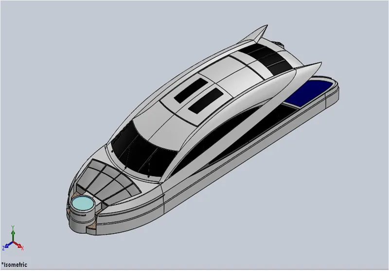
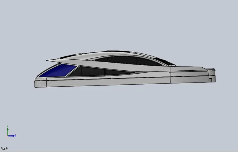
Superstructure:
A superstructure is an extended construction of any
building or platform that rises above the rest of the
building or platform in a distinct manner. ... Thus,
superstructure means to add a construction to an
already existing structure. In ships this is the name
given to the part of the ship that emerges from the
deck.
The features used to create the super structure are:
1.Extrude
2.Sweep
3.Knit
4.Ruled surface
5.Trim
6.Loft
7.Filled surface
8.Projected curves
9.Reference geometry
10.Extend surface’
11.Fillet
12.Chamfer
13.Mirror
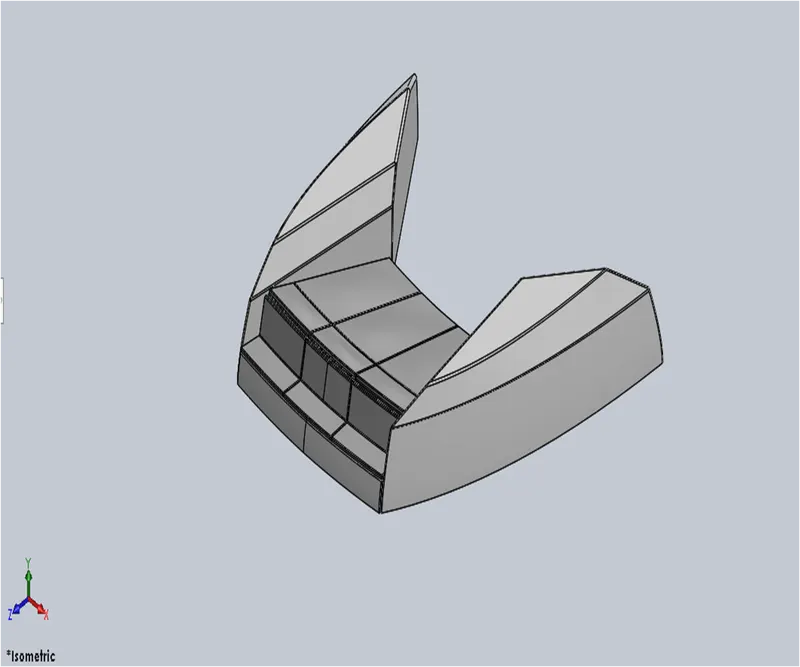
Front seat:
The features used to create front seat are:
1.Reference geometry
2.Sweep
3.Extrude
4.Trim
5.Knit
6.Surface fill
7.Loft
8.Chamfer
9.Revolve
10.Cut extrude
11.Fillet
12.Mirror
13.Dome
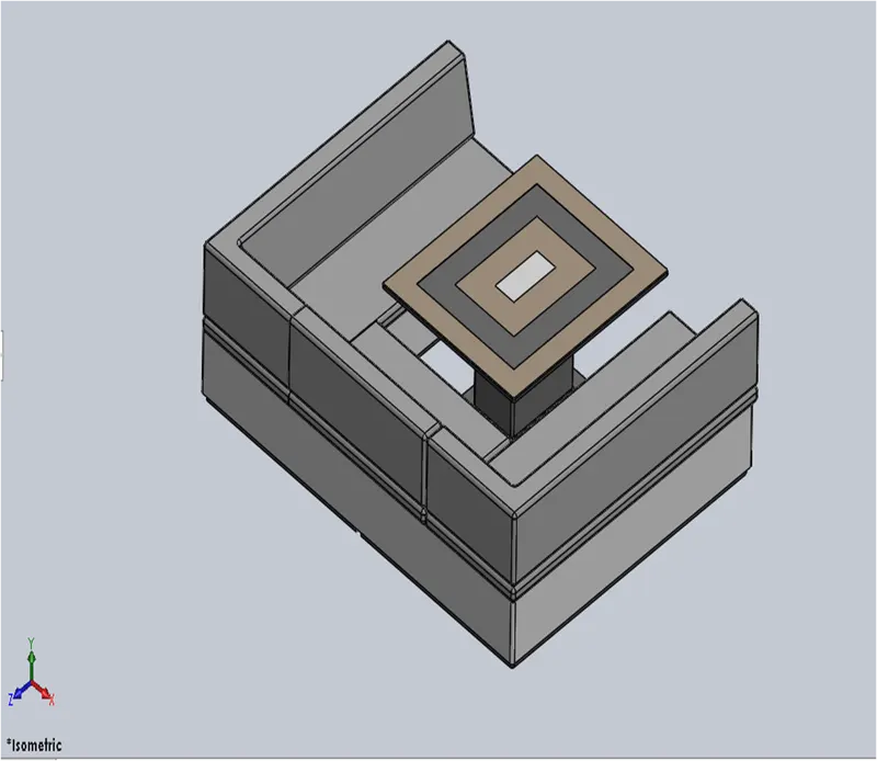
Middle seat:
Features used to create middle seat are:
1.Reference geometry
2.Extrude
3.Chamfer
4.Fillet
5.Mirror
6.Cut extrude
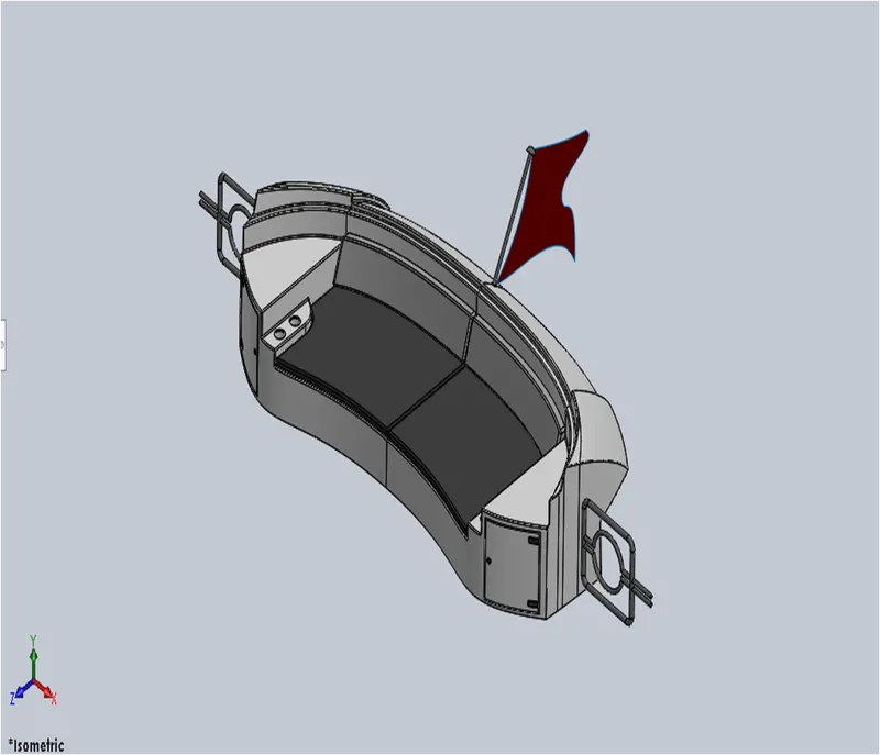
Rear seat:
Features used to create rear seat are:
1.Reference geometry
2.Sweep
3.Offset
4.Trim
5.Ruled surface
6.Knit
7.Extend
8.Extrude
9.Loft
10.Cut extrude
11.Chamfer
12.Fillet
13.Revolve
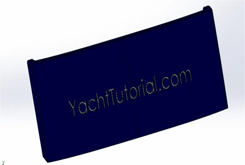
Garage door:
a large door that covers the opening through
which a car enters and leaves a garage.
The features used to create garage door are:
1.Reference geometry
2.Cut extrude
3.Shell
4.Fillet
5.mirror
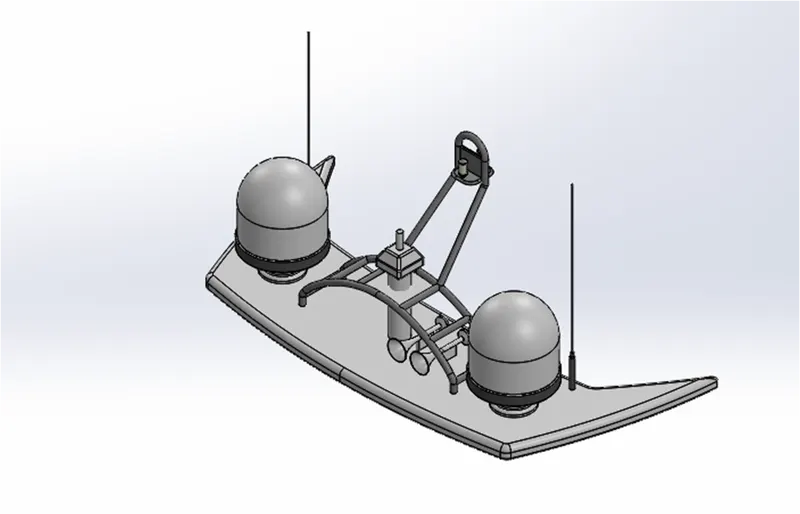
Radar:
Radars are essential for offshore boating or
boating at night or in fog. Radars give the data
related to all the obstacles on the way you are
heading (in miles ahead) to prevent any boat
collisions.
The features used to create radar are:
1.Extrude
2.Fillet
3.Cut extrude
4.Pattern
5.Mirror
6.Split line
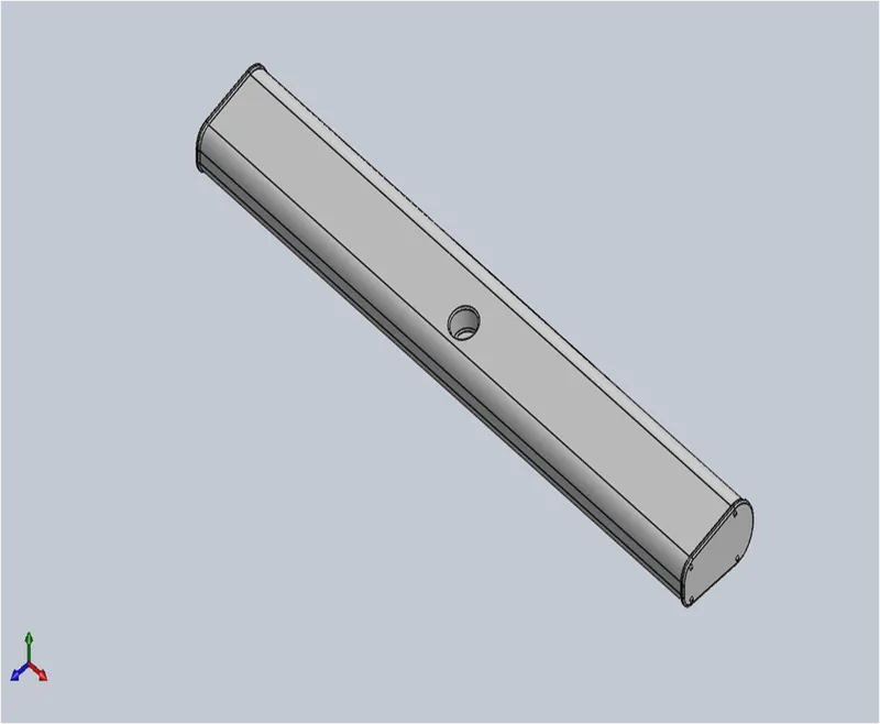
Radar mast:
They are electronic navigation instruments that
use a rotating antenna to sweep a narrow beam of
microwaves around the water surface
surrounding the ship to the horizon, detecting
targets by microwaves reflected from them,
generating a picture of the ship's surroundings on
a display screen.
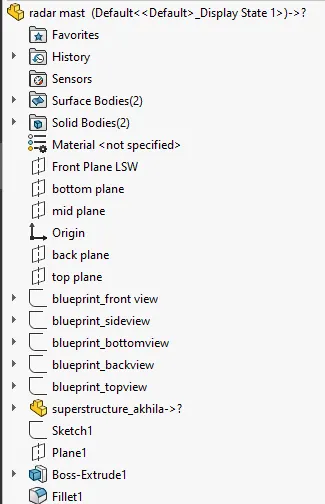
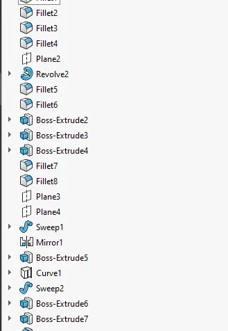
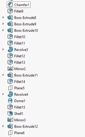
The features used to create radar mast are:
1.Reference geometry
2.Extrude
3.Fillet
4.Revolve
5.Mirror
6.Sweep
7.Chamfer
8.Dome
9.Shell
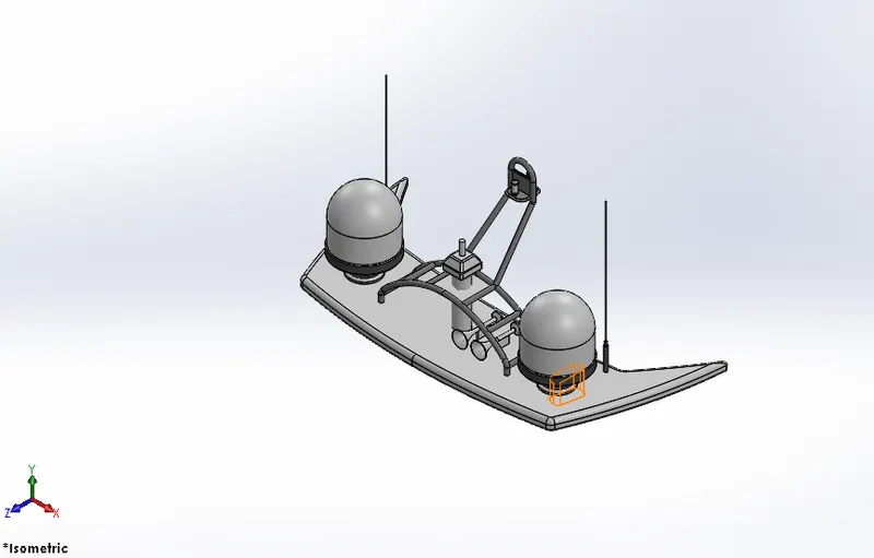
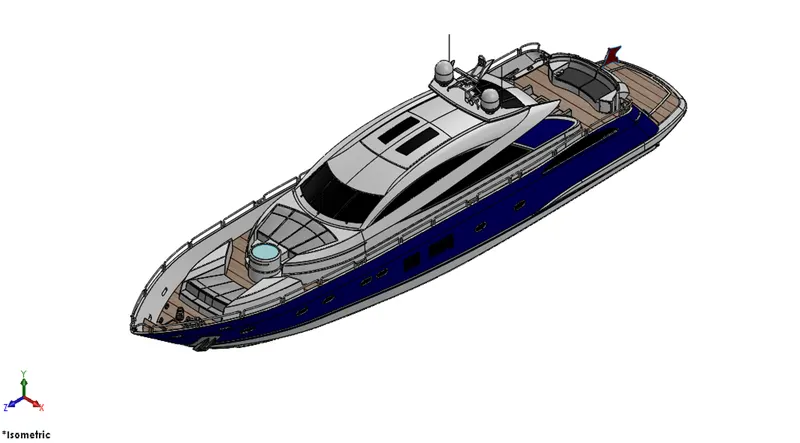
Assembly of yacht :
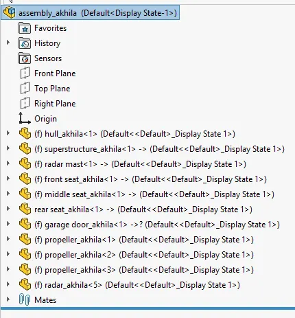
All the parts were modelled and were imported to
assemble them. In assembly mate feature is most
commonly used to locate and relate the parts with one
another. hull is main component which is inserted first and
then fixed. The other components were inserted one by
one and by using planes for reference and giving the mate
feature once the part gets fixed it floats with the main
frame. Some parts were modified during assembly to
make it perfect according to requirement.
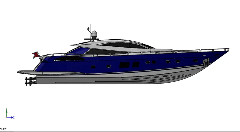
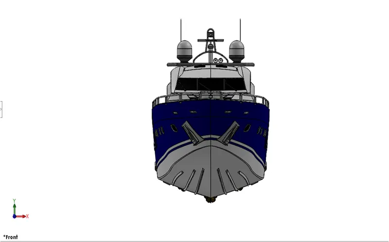
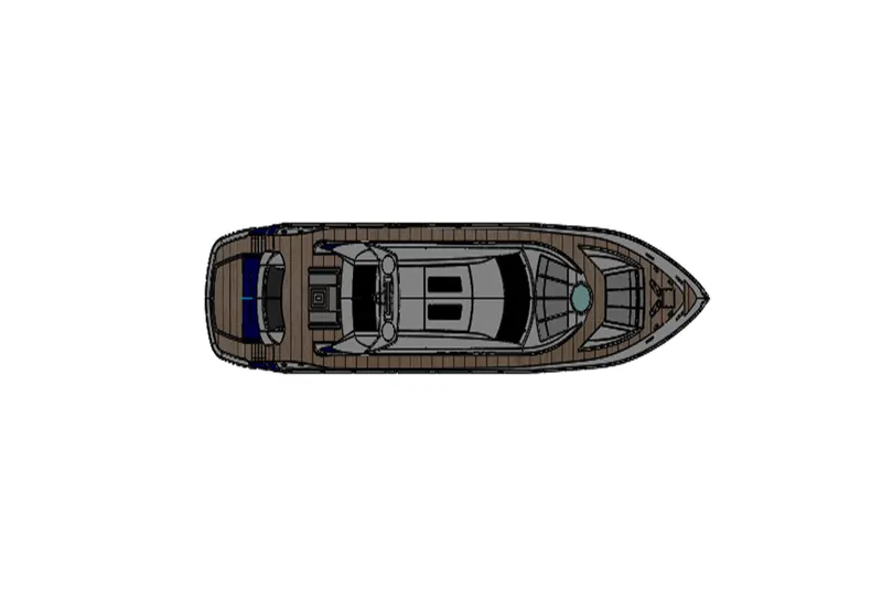
Decals:
A decal is something called a “transfer”, and it
consists of a picture, image, pattern, or design that’s
printed on metal body. We have added decals on hull
of yacht . It gives nice appearance to the yacht.
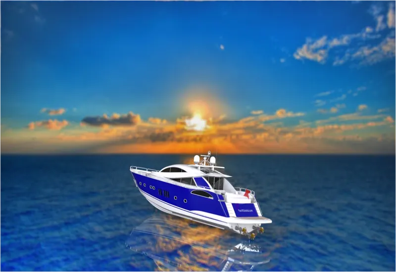
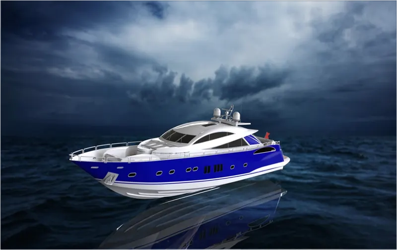
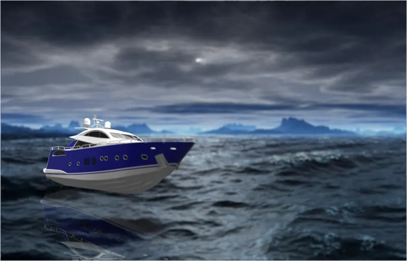
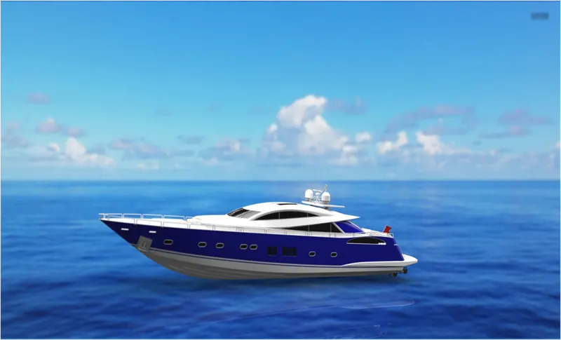
Rendering:
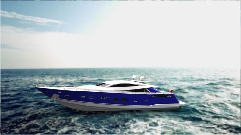
The term rendering comes from the graphic
world where a rendering is an artistic
drawing of what a new structure would look
like. In Computer Aided Design (CAD), a
rendering is a particular view of a realistic
image. By doing rendering of yacht we get
the idea that how it will look into the
environment. This rendering is done in the
SOLIDWORK Visualize software. By using
PHOTOVIEW 360 2 we can add various
camera views to the model, we can set
various angles, direction, and can set
appropriate distance to get the perfect camera
view. In rendering we change color of yacht
parts, background images, brightness,
rotation and various setting of yacht.
Including the resolution and setting number
of passes we get more detail visual’s of
yacht.
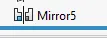
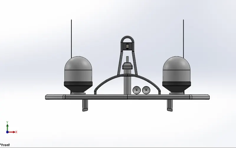
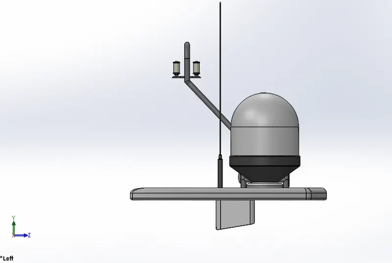
assembly and radar mast feature manager tree and part images are: