Week 9 - Attachment Feature Creation - Challenge 2
Aim: To perform the draft analysis on the coin holder with the engineering features.
Procedure:
To perform the draft analysis, we first need to create the tooling axis. Since we have added engineering features to our coin holder component, we need to create an additional side core tooling axis.
Tooling Axes creation:
1. The first step in the creation of our tooling axis is to inspect the Class-A surface and estimate a tooling axis. We look at the surface from the X Y and Z axes and use the axis that would not require a side core and can conclude that the best axis orientation is from the Y-axis.
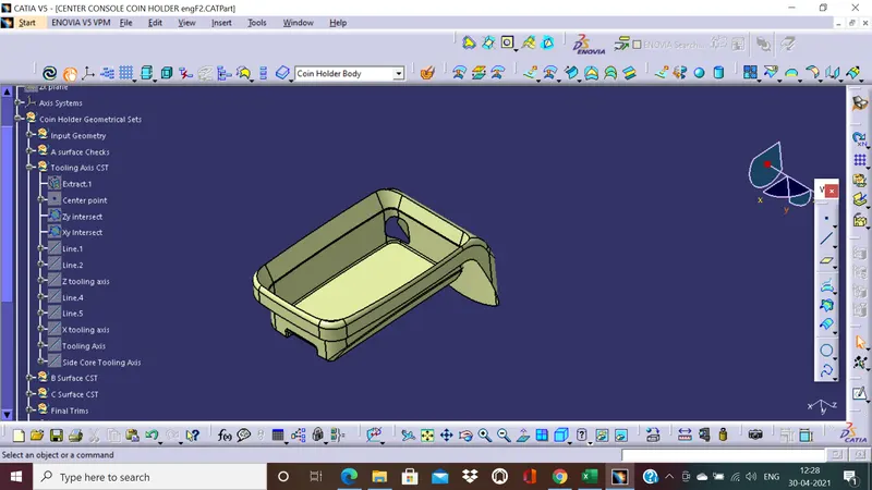
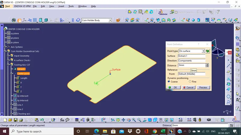
2. We will now extract the bottom face and create a point at the center that is 0mm; naming it the center point.
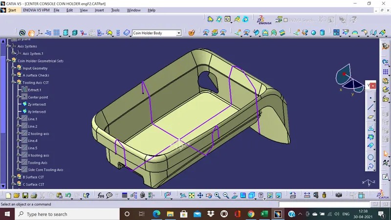
3. Using this point we will create a new axis system, create intersections of the ZY plane and XY planes with the A-surface.
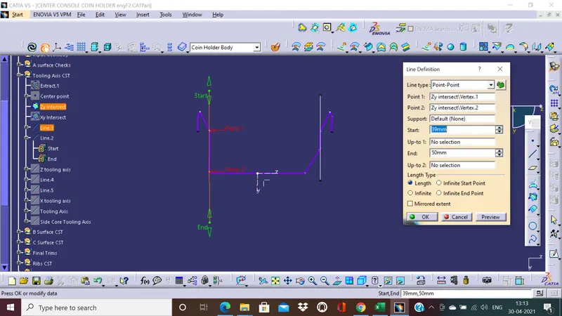
4. Let us focus on creating the Z-direction tooling axis by viewing the Zy intersect from the X-axis; extending two lines made from four points on the intersect that are almost parallel to the Y-axis. The line type is Point to point.
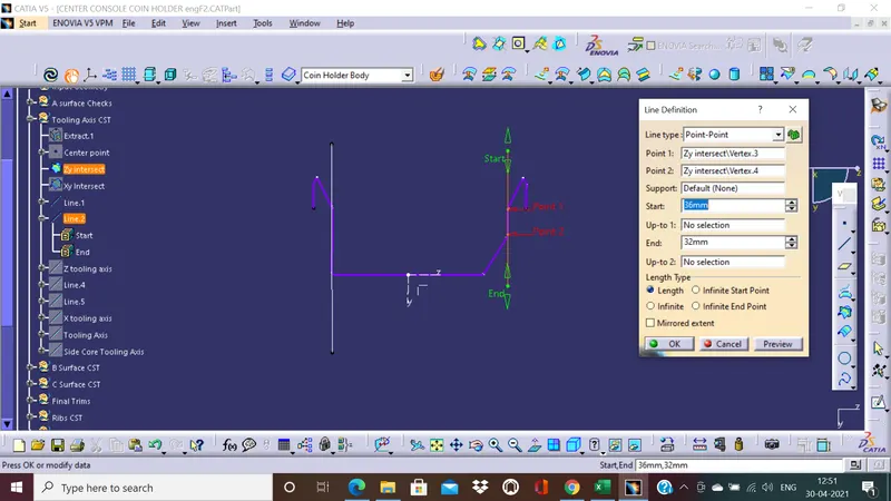
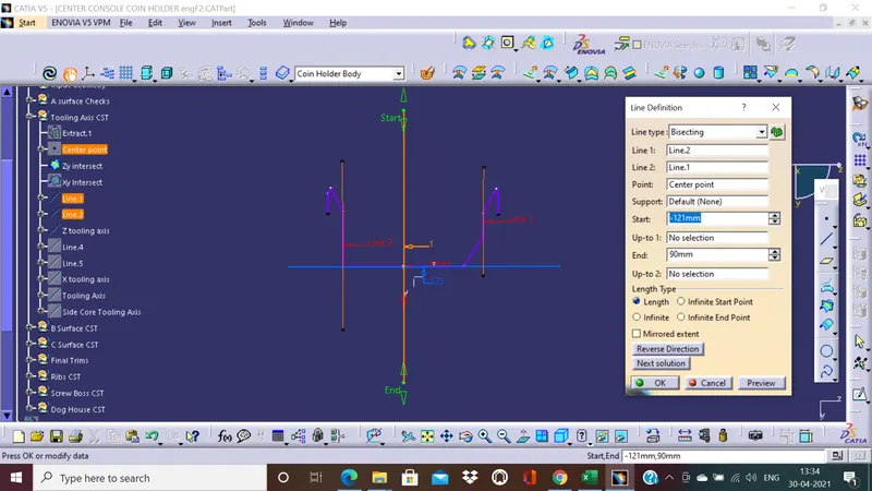
5. Now we bisect the two lines we created and form the Z-direction tooling axis.
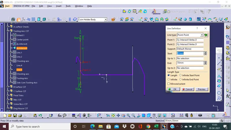
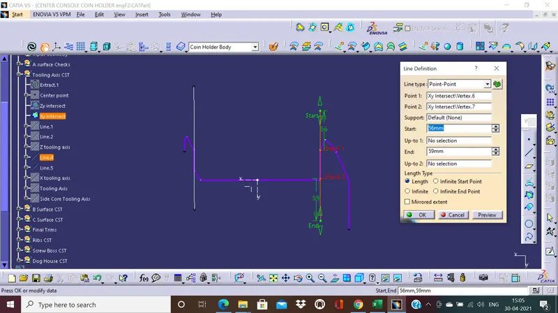
6.Similarly, we create the X direction tooling axis, using the Xy intersect we extend 4 points and create 2 lines. Then bisect them and create our X tooling axis.
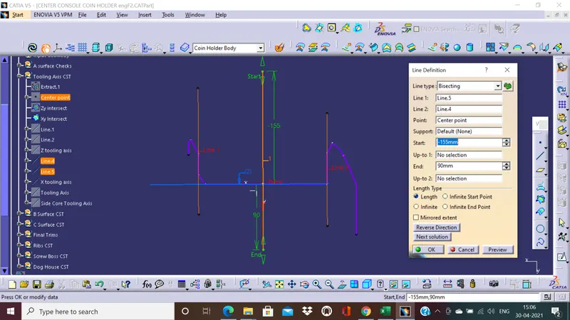
7. We can now create our tooling axis by bisecting the X and Z direction tooling axes.
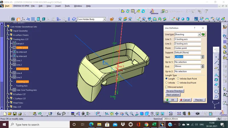
8.Since we are creating engineering features that include a dog house, we need to create a side core tooling axis.
To create the side core, we use the same center point and create a line in the Z direction.
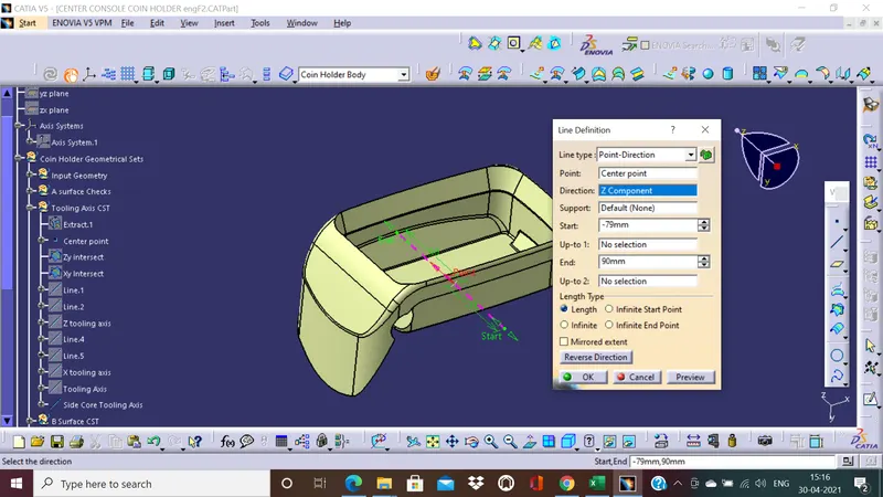
9. We can now perform the draft analysis on our solid part with engineering features.
Draft observations:
Color Codes:
We can set the color codes as per our needs.
The color codes according to the draft angle from the tooling axis is given as follows:
Green: Greater than 3 degrees
Blue: 0 to 2.999 degrees
Red: Less than 0 degrees.
A-surface observations:
We observe that our A surface is having areas in green blue and red. This can be seen from the images below.
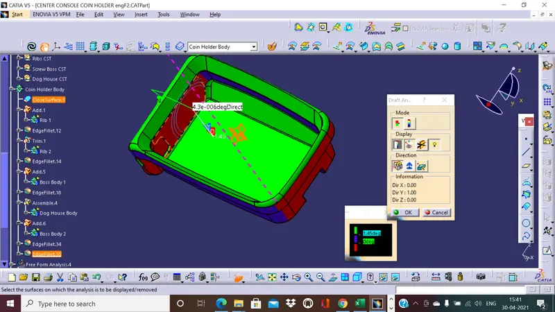
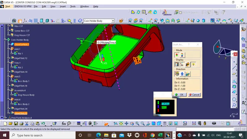
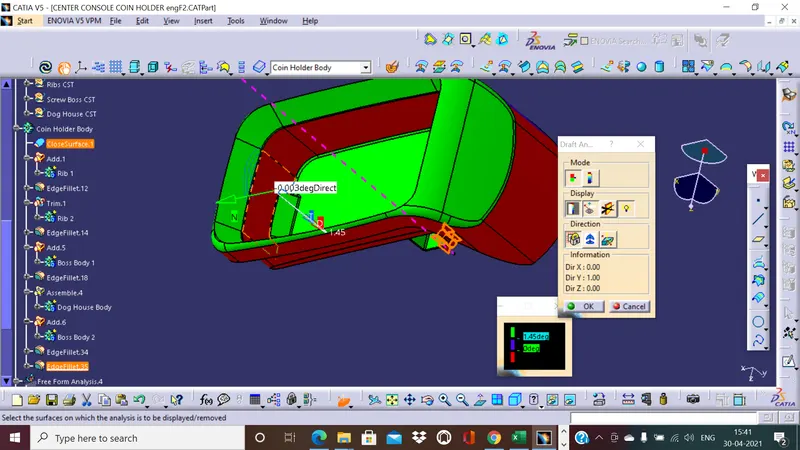
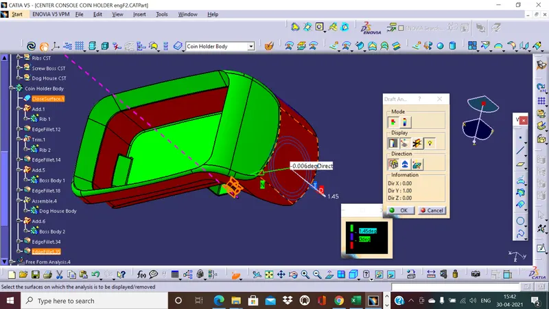
We observe that the A-surface side of the component is not designed keeping manufacturability in mind. The area in green is fine but the red and blue regions indicate regions that are almost perpendicular to the base. The minimum angles are -0.096 angles which will result in a bad quality surface finish.
Now let us look at the B-surface areas that have engineering features. The minimum draft we need here is 1.45 degrees as engineering features do not require an excellent surface finish. The customer will not be seeing these features so this draft angle is acceptable for use and manufacturable.
New color codes:
Green: Greater than 1.45-degree draft angle
Blue: 0 to 1.499-degree draft angle
Red: Negative draft angles
Let us focus on the dog house for this draft analysis.
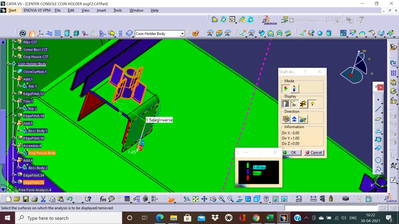
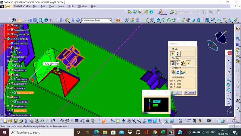
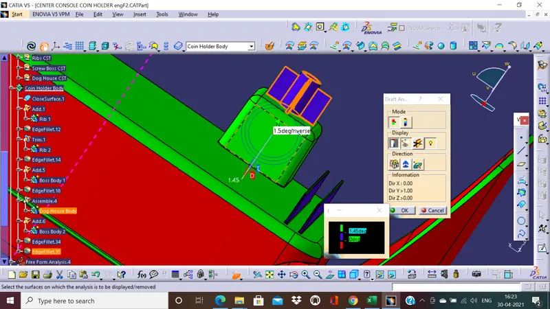
We have created a side core tooling axis to mold the inner face of the dog house. The draft analysis of the inner face of the dog house is shown below.
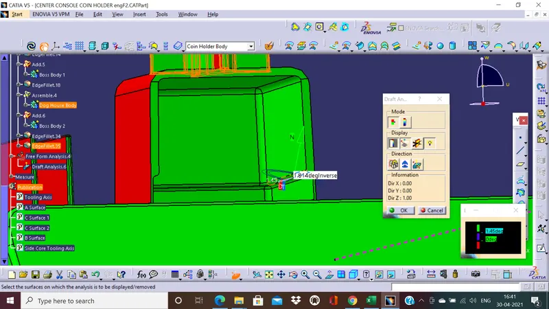
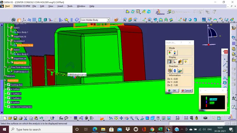
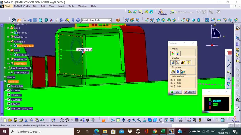
The dog house can be seen clearing the minimum draft tooling angles of 1.5 degrees from all the needed directions.
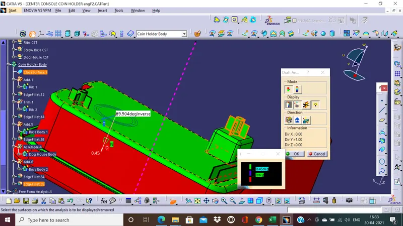
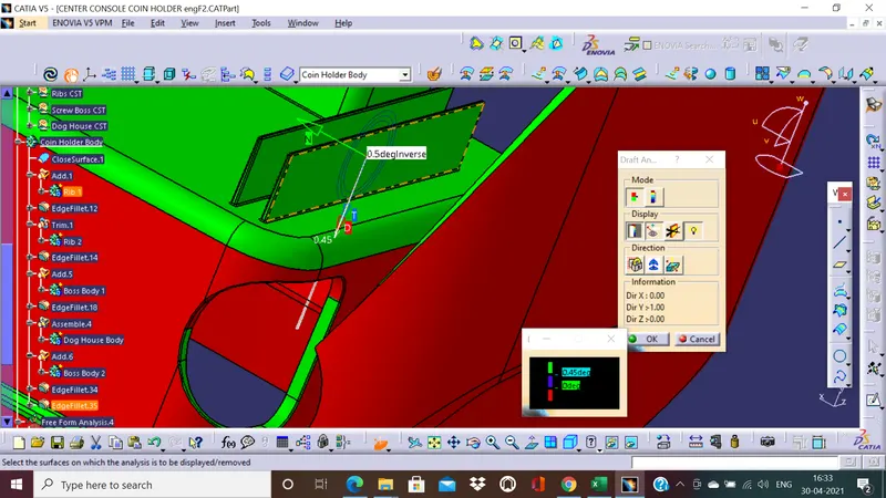
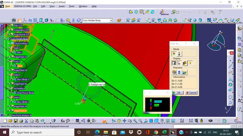
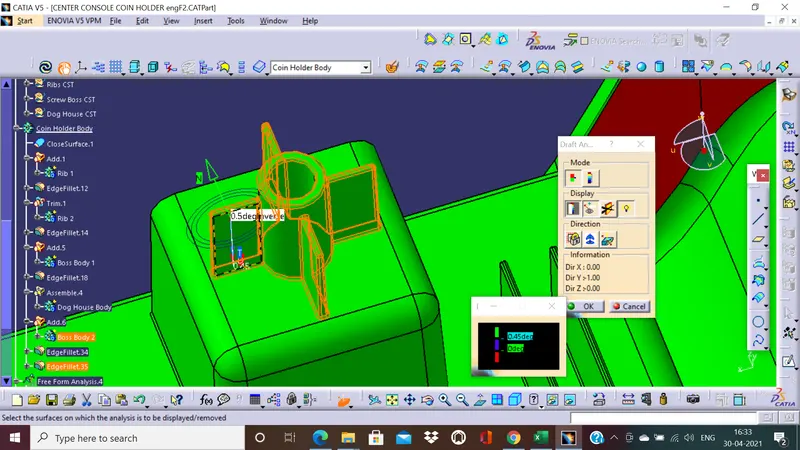
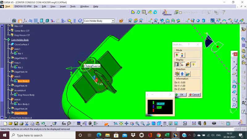
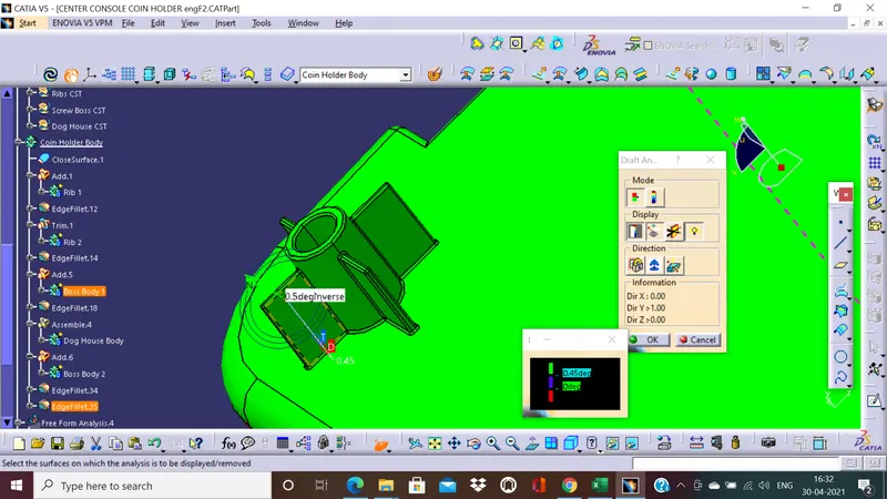
Next, we shall focus on the draft analysis of the screw bosses and ribs we have. They need a lesser quality surface finish than the dog house and are designed with a minimum draft angle of 0.5 degrees from the main tooling axis. We shall define a new color code range as follows:
Green- greater than 0.45-degrees
Blue- 0 to 0.499-degrees
Red- Less than 0 degree
Conclusion:
From the observations of the draft analysis on the component, we see that the components A-surface has to be redesigned keeping in mind draft angles of atleast 3 degrees. Once this is done, we can get a good surface finish on the final molded part on the surface the customer can see and feel.
The B surface engineering features are designed keeping in mind draft angles of 1.5 degrees (dog house) and 0.5 degrees (ribs and screw bosses) as a minimum from the tooling axes.
The draft analysis of the component is now completed.
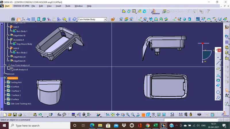
Different views of the component:
Q1:Left side view
Q2:Isometric view
Q3:Front view
Q4:Bottom view
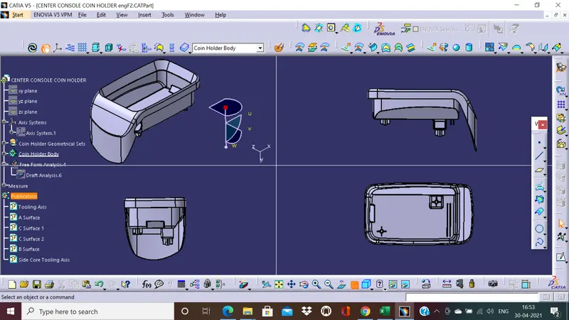
Q1:Right side view
Q2:Isometric view
Q3:Back view
Q4:Top view
Please see the attached compressed file for the part. Thank you.