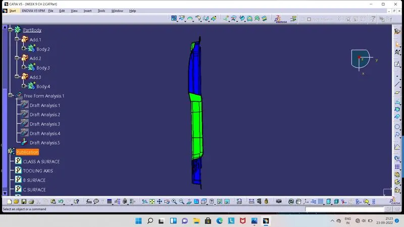
Week 9 - Attachment Feature Creation - Challenge 2
- Screenshots of Draft Analysis report for the given Class A Surface :
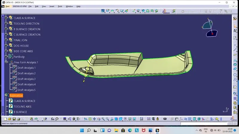
- For Draft Analysis, we need Tooling Axis. So here we have selected a circle like base surface and create center point on it.
- From that center, we have created normal line to the surface.
- We have choose this direction because, in this direction whole component is visible properly, so its a way to create Tooling Axis in such direction, so that is our Tooling Axis.
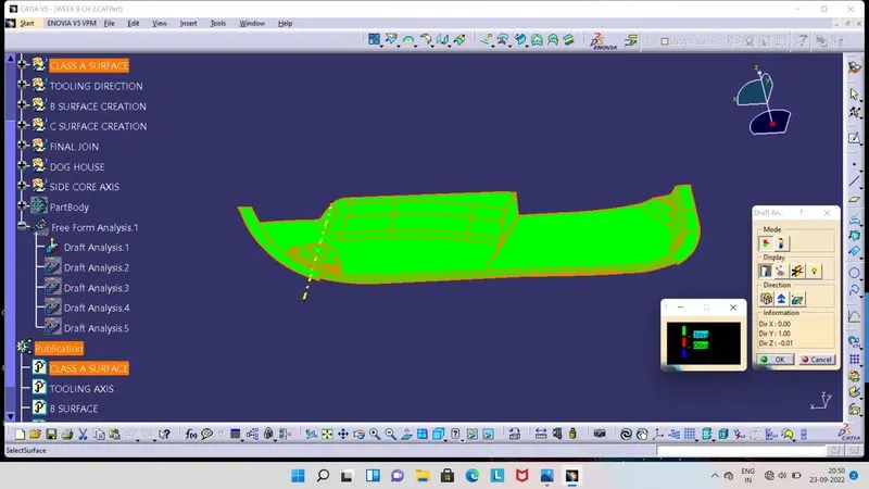
- As we get Tooling Axis, we can go for the Draft Analysis by click on Feature Draft Analysis tool.
- We have to ensure that our component is in the material view mode.
- As a Draft Analysis tool open, we can see that 2 boxes as shown in image in right side of the screen.
- Then click on Compass, so compass will be seen on screen. Do align this compass with Tooling Axis and click on lock symbol.
- Then click on Class A Surface, so surface get colour on it.
- Green colour indicates that, draft angle is above the 3 degrees.
- Red colour indicates that, draft angle is between 0 to 3 degrees.
- Blue colour indicates that, draft angle is below 0 degree or negative.
- Screenshots of Draft Analysis report for the Plastic Component :
- Class B Surface :
- Its offset surface of Class A Surface.
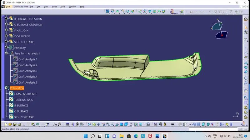
- Class C Surface :
- Its a joining surface of Class A and B Surfaces.
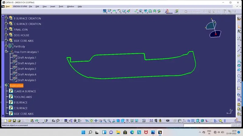
- Joining Surfaces of Class A, B and C.
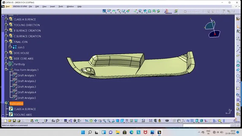
- Final Plastic Component :
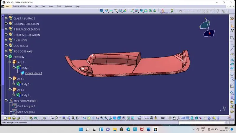
- Draft Anlysis for the Final Plastic Component without the Dog House.
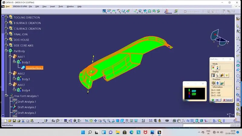
- For the Draft Analysis by click on Feature Draft Analysis tool.
- We have to ensure that our component is in the material view mode.
- As a Draft Analysis tool open, we can see that 2 boxes as shown in image in right side of the screen.
- Then click on Compass, so compass will be seen on screen. Do align this compass with Tooling Axis and click on lock symbol.
- Then click on Final Plastic Component, so component get colour on it.
- Green colour indicates that, draft angle is above the 3 degrees.
- Red colour indicates that, draft angle is between 0 to 3 degrees.
- Blue colour indicates that, draft angle is below 0 degree or negative.
- Screenshot of Drfat Analysis Report for the Dog House :
- Dog House is a one extra component added at main component for prevention from Sink Marks.
- Dog House can solve lenght issue of Screw Boss.
- If Screw Boss is perpendicular to the Tooling Axis, then we have to use Dog House.
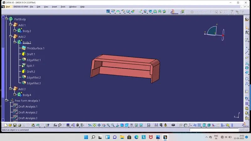
- For Designing of Dog House, we have to use several standard values to prevent the component from plastic defects.
- Width of the Dog House should be a minimum 12mm, so here we have kept as a 35.1 mm.
- Here ratio of Width of Dog House to its Height should be a 3:1, so by this relation we get value for the Height is 11.7 mm.
- Draft should be 1.5 degrees, so we have given 1.5 degrees at outer surface of the Dog House by using Sweep tool and with Tooling Axis.
- For Draft in inner surfaces of the Dog House, we need another axis, which will be perpendicular to the Tooling Axis, which is our Side Core Axis.
- So here we give Draft at inner surfaces of Dog House with 0.5 degrees.
- Wall thickness of the Dog House from its base and between height of 3mm to 6mm should be a 0.4 × Thickness of the Plastic Component.
- So we have take 4 mm height and as thickness of plastic component is 2.5 mm, so we get 1 mm as a wall thickness for the Dog House upto the 4 mm height from the base of it.
- We have Given 2.5 radius fillet at outer side of the Dog House and O.5 radius fillet at inside part of the Dog House.
- Drfat Analysis of Dog House as the reference of Tooling Axis :
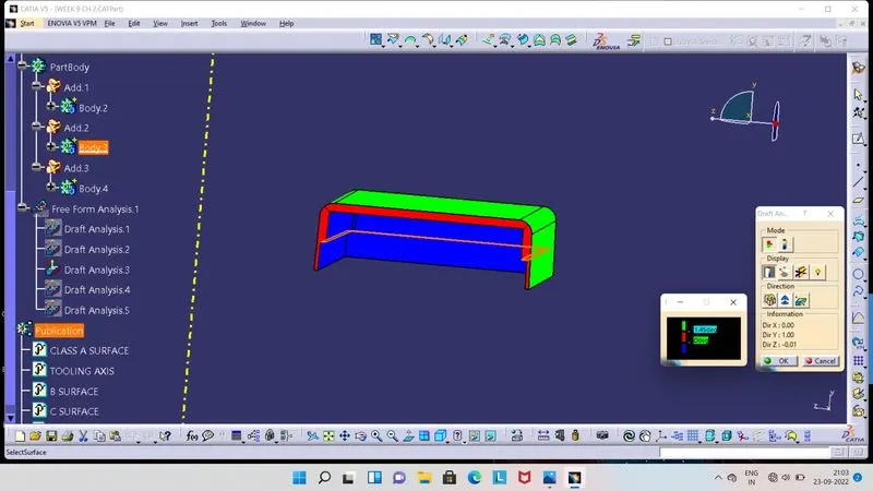
- Draft Analysis of Dog House as the reference of Side Core Axis :
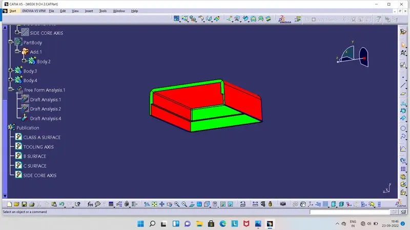
- Draft Analyis of both the Dog Houses :
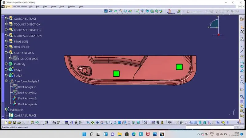
- Final Plastic Component with Dog Houses :
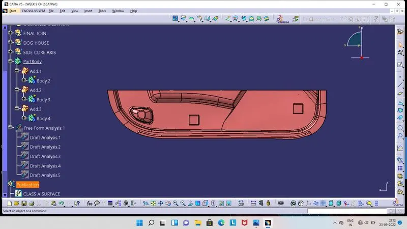
- Drfat Analysis of Final Plastic Component :
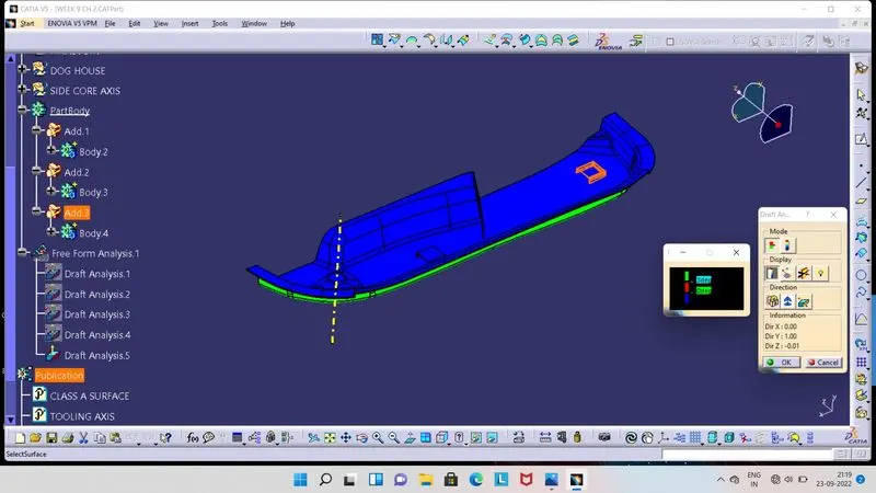
- Screenshots of the completed design in various orientations.
- Isometric View :
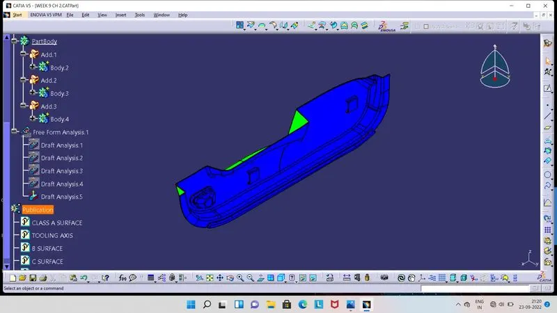
- Front View :
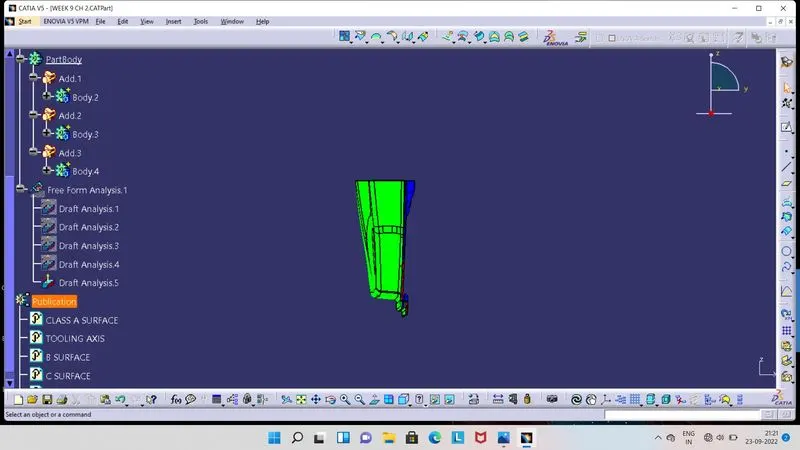
- Side View :
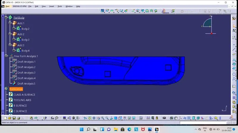
- Top View :