Week 9 - Attachment Feature Creation - Challenge 2
AIM:
- To produce the Door Trim Component using the provided Class-A surface as the starting point.
- In order to fulfil the requirements of the drafting angle, it is necessary to create the Tooling axis for the Class-A Surface that has been provided.
- For the purpose of carrying out the Draft analysis on the model.
- To create Dog House
DESCRIPTION:
1. INITIALIZATION OF THE TOOLING AXIS -
The Tooling Direction refers to the general path that a part is pulled in when it is being formed in a mould. Essentially, the mould is constructed using two distinct components that are joined together. One of your sides is the Core side, while the other is the Cavity side. When the Core is pulled away from the Cavity in this direction, the Dye line (also known as the Tooling Direction) may be seen.
Launch the CAT part file that has been provided.
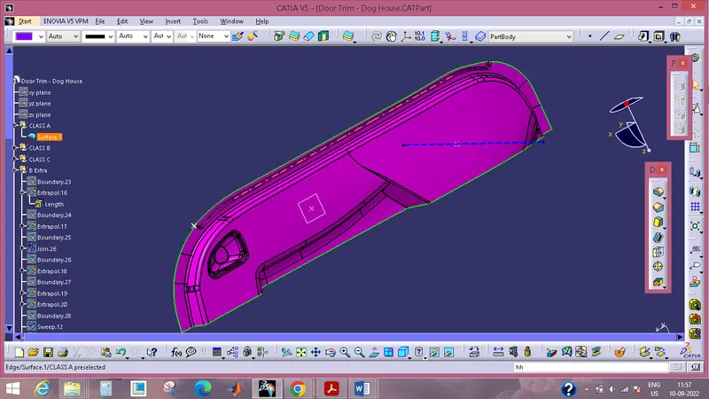
- To check for gaps between surfaces, click the join button, and then click the preview button.
If there is any space between the two surfaces, you should attach them with a tolerance of no more than 0.003 millimetres. - The border should be extracted, and then the boundary should be disassembled.
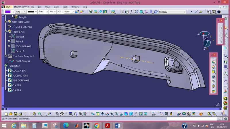
- Find the correct tooling axis so that the elements can be generated without the tooling axis being obstructed by the material.
- Perform an intersection with the yz plane using the class A surface as the reference point.
- Cover up the class A surface and draw point-to-point lines across the areas where draft are suspected.
- In order to work on the component, the tooling axis is developed.
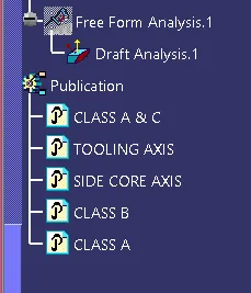
DRAFT ANALYSIS
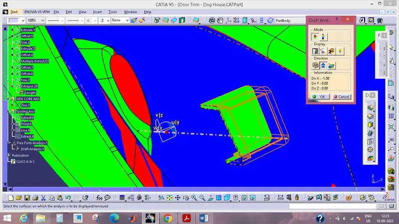
Using the Draft Analysis command, you will be able to determine whether or not the component that you drafted will be simple to remove. This kind of analysis is carried out based on colour ranges that designate areas on the element that is being evaluated in which the deviation from the drafted direction at any point corresponds to predefined values.
CREATING CLASS B SURFACE
- Utilizing various extract methods, remove the surfaces from the class A and leave them untrimmed.
- Make sure that all of the untrims are properly intersected by using the Extrapolate tool in order to trim and offset the surfaces to a total of 2.5 millimetres in order to achieve the thickness.
- Remove any unnecessary surfaces by using the trim command.
- They should be inserted into a new geometrical set, and the set should be given the names of the respective parts.
- After the surface has been created in its entirety, fillets should be applied to the model.
- If the component's edges are located on the exterior, the fillet value will be added to the thickness of the component; however, if the component's edges are located on the interior, the fillet value will be subtracted from the thickness of the component.
- To ensure that everything is crystal clear, it is best to perform the trims one at a time.
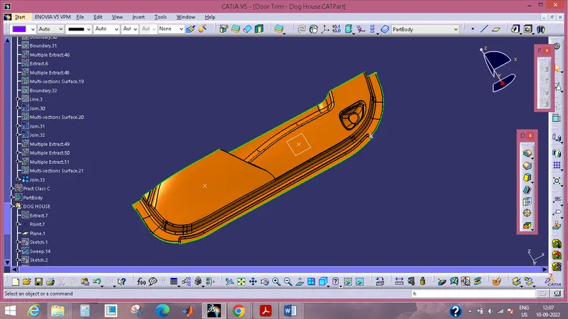
FORMATION OF A SURFACE OF CLASS C
- Applying the boundary command to the class A surface will allow you to obtain the border.
- The disassemble tool will be used to divide the border, which is necessary because the boundary contains domains.
- Use the sweep command, then select profile type line, then select subtype as with drafting direction, then select guide curve and drafting direction, then set the drafting angle to 3 degrees, and finally, preview the result.
- Following the completion of the sweep, the output will need to be trimmed using a class B surface before it can be considered final class A & C.
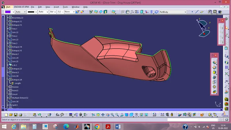
Now open the part design workbench, and using the component's near body surface, make a solid representation of the part.
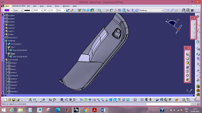
Building a Dog House
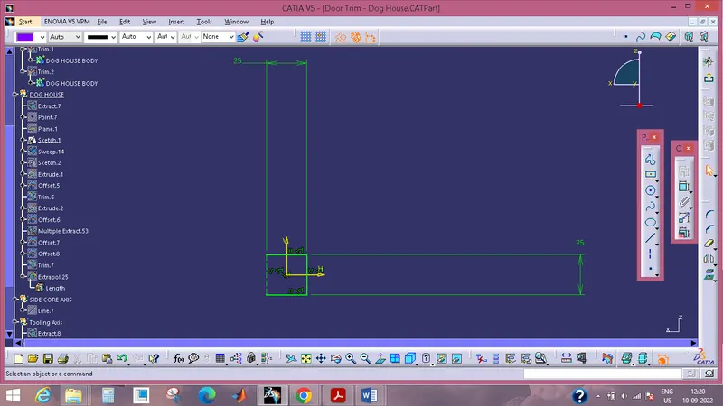
The schematic that was used to create the dog house
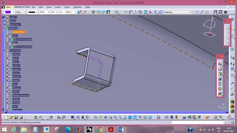
DRAFT ANALYSIS OF DOG HOUSE USING SIDE CORE AXIS:
PUBLICATION: