Week 9 - Attachment Feature Creation - Challenge 2
AIM
Create the Dog House for the Door Trim considering the design rules and perform Draft analysis.
THEORY
CLASS A SURFACE: Class A surface is a surface made by the designer specially in automotive design which is the aesthetic part of a body and is given as an input to the plastic designer to work on it.
CLASS B SURFACE: It is a surface which comes below the class A surface with a particular thickness. This surface contains engineering features of a model.
CLASS C SURFACE: It is the surface which joins class A with class b surface.
TOOLING AXIS: Tooling axis is the direction in which the core and cavity opens. If we are using proper tooling axis, we can avoid adding side cores thus the cost of manufacturing the component can be reduced.
It is defined as the direction in which the mould/core and cavity open. Selection of the direction of the tooling axis depends on the ease at which components can be easily ejected.
Generally tooling axis is decided from the natural axis of the design, that is, tooling axis is analysed with the x, y and z axis of the system. If the axis doesn’t clear the draft analysis, the next step is to look for the surface in which the drafting axis can be created in such a way that the axis is normal to the surface taken. These are the methods of deciding tooling axis. Bisecting method is the least used method.
BISECTING METHOD: It is a method used to create tooling axis.
Here, I had used axis direction as the tooling axis. Because, Bisecting method is rarely used and not proper method of using tooling axis. Using bisecting method to have tooling axis have many limitations. So, while creating a tooling axis, it is recommended to look for the directions in the axis system to have draft analysis. If those axis system doesn’t clear the draft analysis look for normal to surface to have a tooling axis.
DRAFT ANALYSIS: From draft analysis, we can verify draft angles, examine the angle changes within a face, as well as locate parting lines, injection and ejection surfaces in parts.
It is an important feature in Catia which helps the user to analyse the draft on various surfaces. The draft analysis toolbar provides two modes for analysis of the draft, first is the quick analysis which basically has three colours (green, red, and blue) for analysing on the other hand other option is the full analysis mode which enables a few more details into the draft and is used in the complex components.
Draft analysis in Catia:
Step 1: Ensure that customize view parameter is enabled and material mode is opted in view mode customization.
Step 2: Now go to insert > analysis > feature draft analysis.
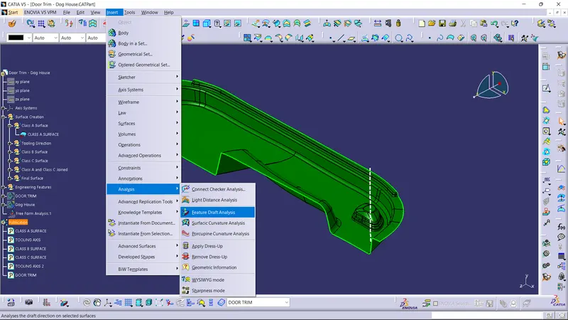
Step 3: Drag axis bar to the tooling direction of part.
Step 4: Check for draft.
Surface will be in green if the draft angle is more than 3 degrees, blue if draft angle is between 0 to 3 degree and red if draft angle is less than zero degree.
Three degree is the nominal value for draft, whereas 0.5 degree can also be manufactured at ribs.
DOG HOUSE: It is an engineering feature used in plastic trim design. It is used as a supporting feature. By using dog house, we can support the other engineering features like heat stakes, screw boss and locators to locate them at a certain height where we cannot violate the design rules for the features. By using doghouse, we can avoid sink marks in class A surface.
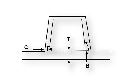
Doghouse wall thickness at the intersection of the part wall ( C ) should be 40% or less than the main wall stock ( T ).
The height of ( B ) should be between 3.0 – 6.0 mm
OBJECTIVES
- Creation of Tooling axis
- Creation of Class B and Class C surface from provided Class A surface.
- Creation of solid part out of surface modelling.
- Create engineering features.
- Draft analysis of Class A surface and final part.
PROCEDURE
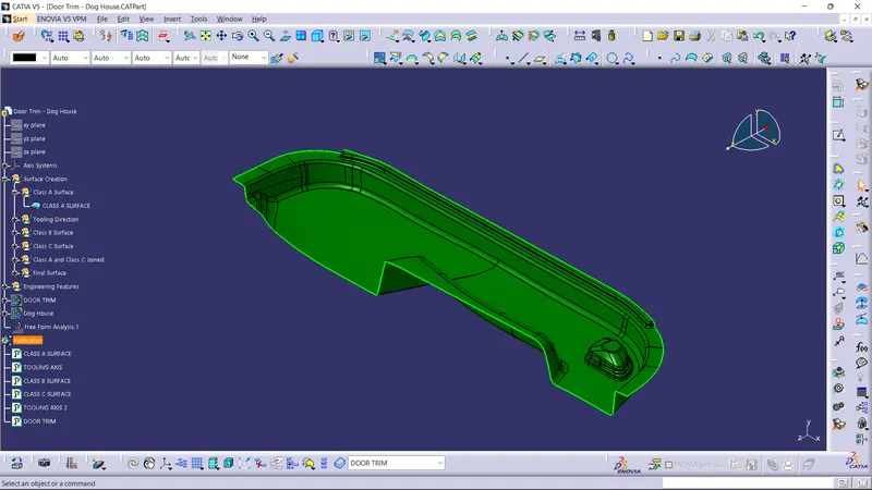
Creation Of Class A Surface
- Class A surface is obtained as the input.
- Join all the surfaces to obtain Class A surface if different surfaces are given as input and ensure no gap is present between any surfaces. Thus, Class A surface is obtained and publish it. Here, the provided surface is completely joined and can be taken as class A surface.
- Publish class A surface.
Creation Of Tooling Axis
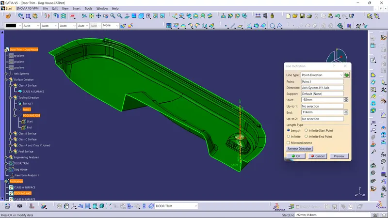
- Tooling axis here created is by selecting one of the natural axes as it clears the draft.
- Here, tooling axis is created by extracting one of the surfaces for creating a point and a new axis is created at that point.
- So, a flat face is extracted and created a point at its centre. Axis is also created at that point.
- Now, line is created using line tool and giving line type as point-direction and selected the point and direction for creating tooling axis. Tooling axis is created along y direction.
- Publish Tooling axis.
Draft Analysis Of Class A surface
- Draft analysis is performed over Class A surface and every surface is obtained as clearing.
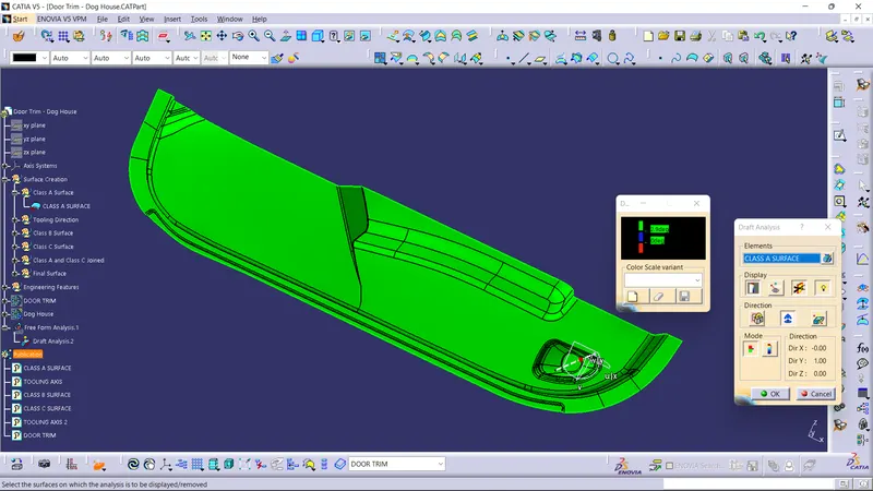
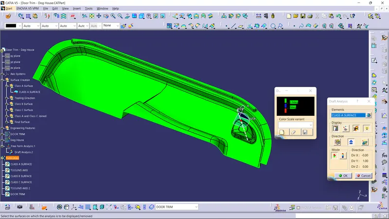
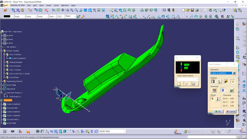
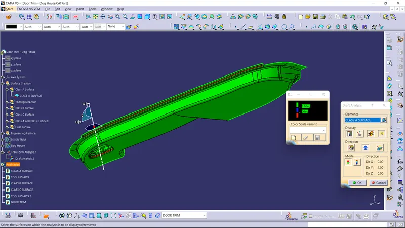
After performing the draft analysis, it is seen that whole A Class surface is not clearing the draft. Minimum of 3-degree draft is not provided on some faces. So, as a plastic product designer, it is recommended to the A Class designer to change the A class surface in such a way that to modify A class surface.
Creation Of Class B Surface
- Now, Class B surface has to be created. For this surface should be offsetted for 2.5mm.
- Publish class B surface.
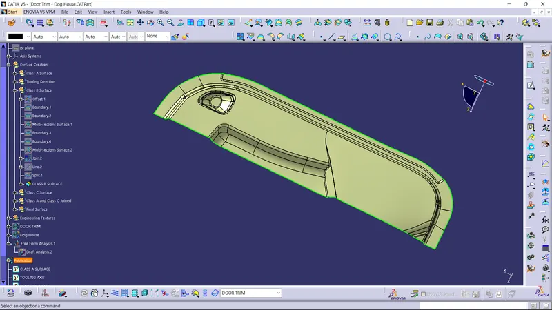
Creation Of Class C Surface
- Now class C surface has to be created and it is created from the boundaries obtained from the Class A surface. This boundary is provided as the input curve for sweep command. Using sweep command, class C surface is created.
- Appropriate sweep is the provided considering the flash and considering manufacturing procedures. Surfaces are extrapolated if necessary.
- Publish class C surface.
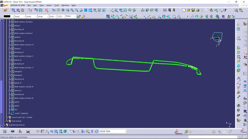
Creation Of Closed Surface
- Now Class A surface and Class C surface is joined.
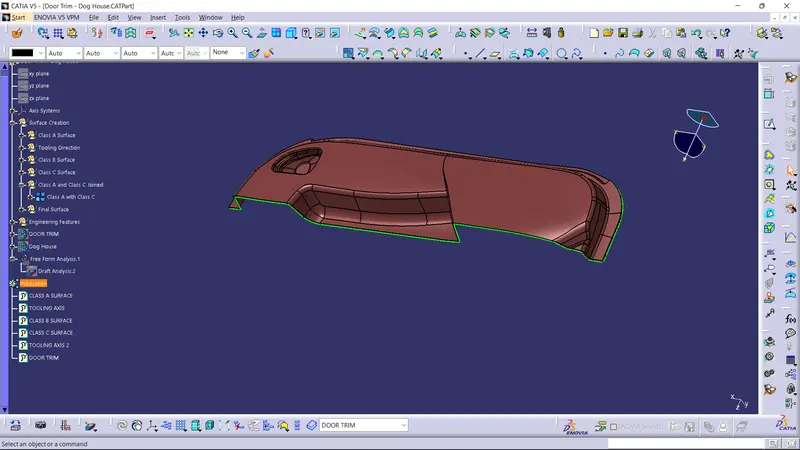
- Now Class B surface is also trimmed with the obtained surface to get the closed surface.
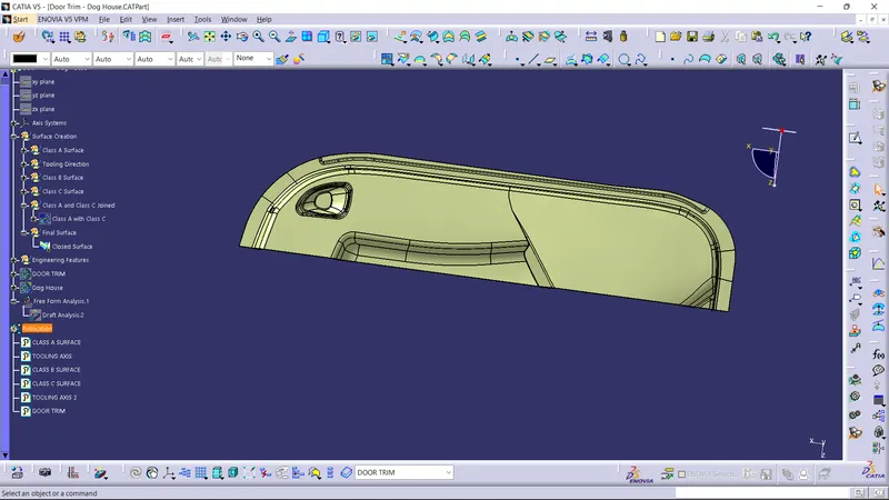
- Boundary check is done to check for any open boundaries in the part.
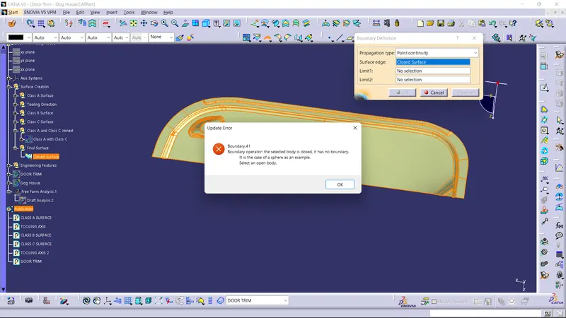
- The closed surface then obtained moved to part design and close surface tool is used to obtain the part.
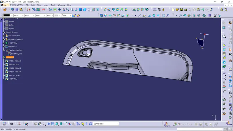
Draft Analysis Of Plastic Component
- The obtained part is draft analysed to check for the correctness of obtained model by following the draft analysis procedure mentioned above.
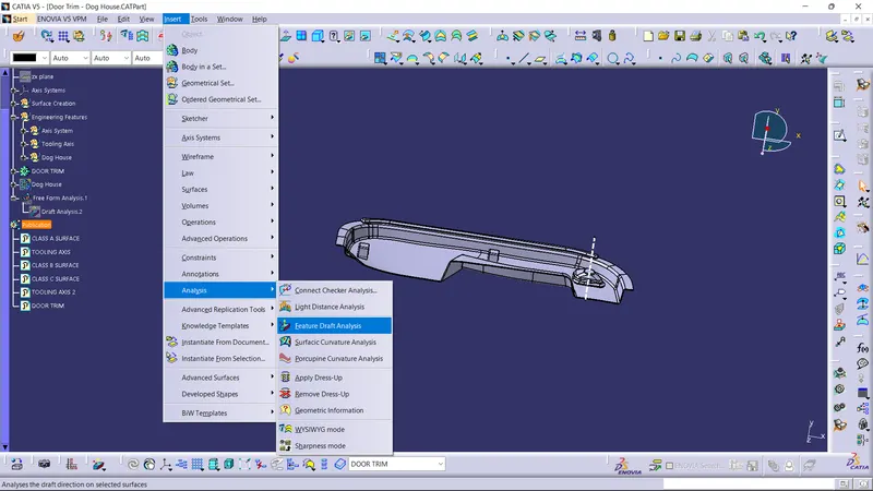
Screenshots Of The Solid Model With The Proper Color Code Of The Draft Angle In Various Orientations
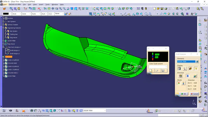
Class A Surfaces obtained are all green in color, which means that the surfaces are clearing the draft analysis. The faces that are obtained in red will be clearing in core side, as the draft direction is reversed, those red faces will be turned to green which means those surfaces are also clearing draft analysis.
As mentioned before, some of the faces are not clearing the draft analysis, for that to clear, A class surface has to be modified.
Creation Of Doghouse
- Doghouse are created by following the design rules.
- For this, a sketch is created and a rib is drawn.
- It is the padded by inserting a new body.
- Drafts are given for the surfaces as per design rules. Shell operation is also performed to get the proper surface.
- For coring, another sketch is created and it is padded and removed from the main surface.
- Proper fillets are also provided.
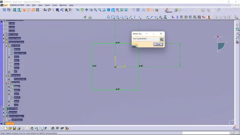
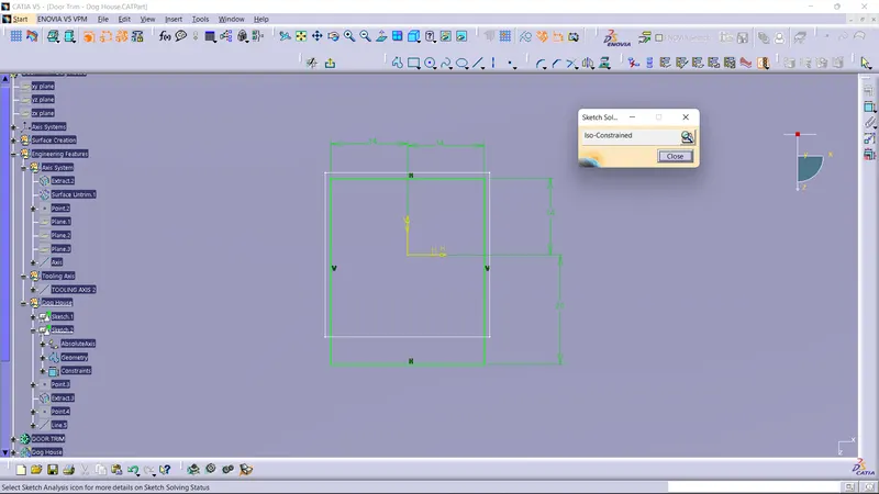
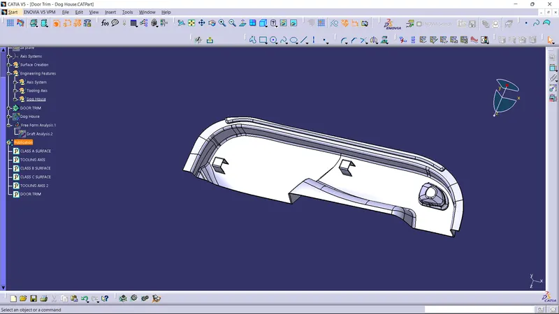
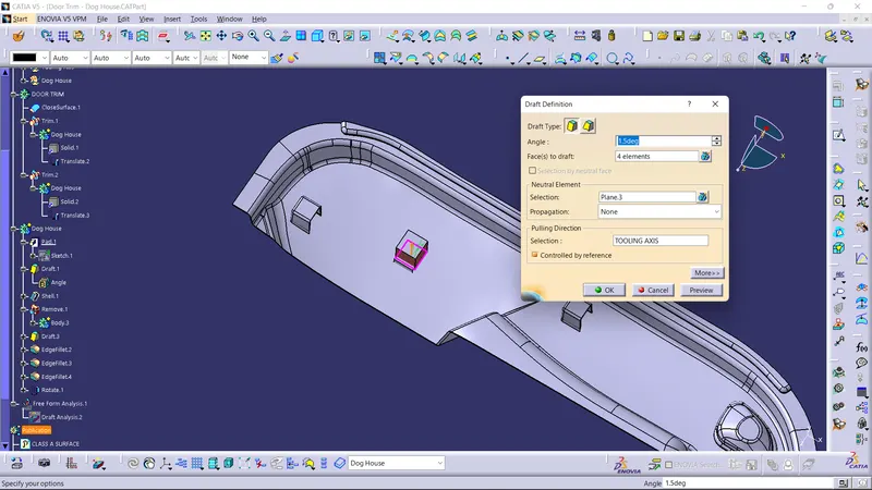
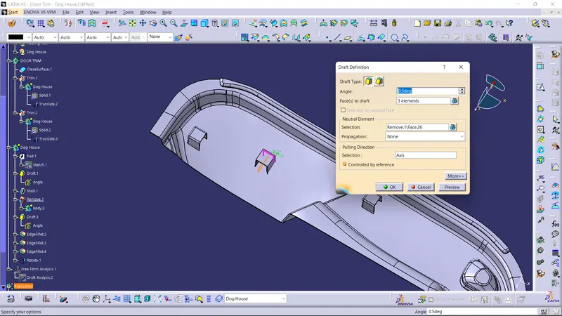
Thickness of the component, t = 2.5mm
Minimum draft in outer surface = 1.5-degree
Minimum draft in inner surface = 0.5-degree
Doghouse wall thickness, C = 0.4*t = 1mm
Height, B = 3-6 mm
Fillet radius = 0.25mm
Here a dog house is created and it is copied and pasted on another body. It is then transferred using point to point option and it is placed in the desired place.
Draft Analysis Of Plastic Component
- The obtained part is draft analysed to check for the correctness of obtained model by following the draft analysis procedure mentioned above.
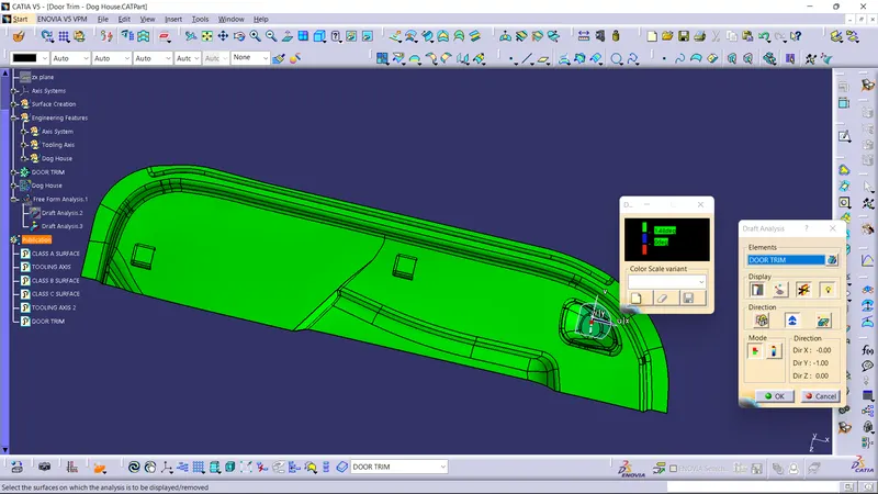
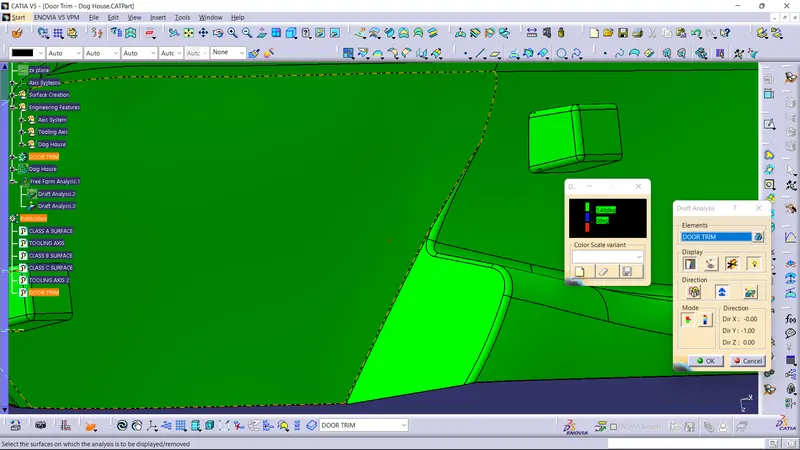
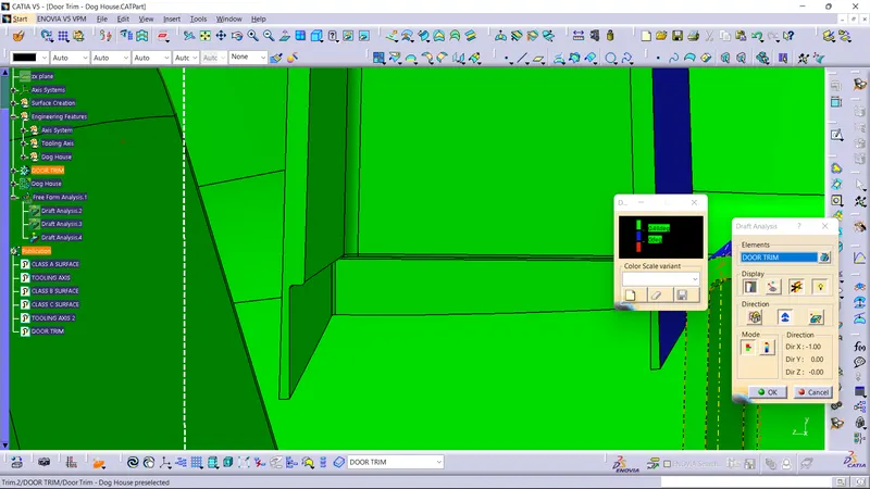
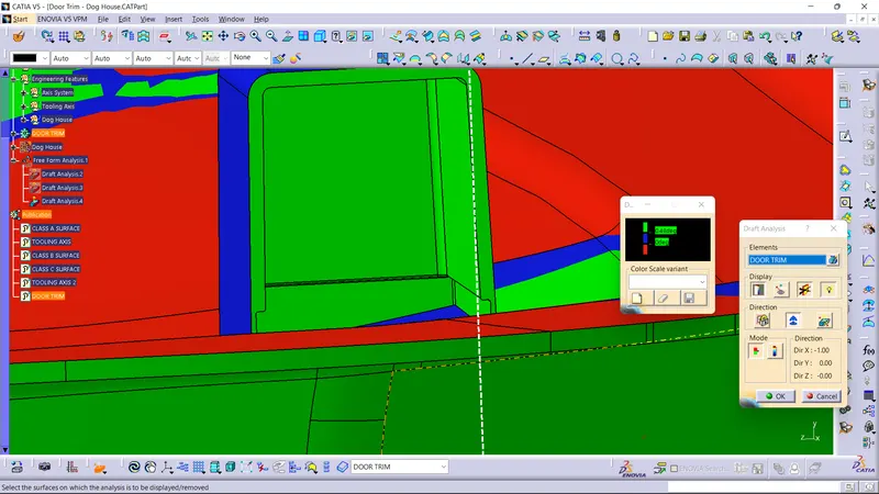
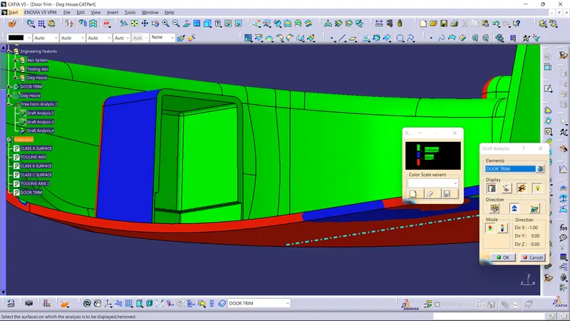
Side core has to be created for the doghouse to get ejected. So, a side core axis is also created for checking the draft analysis of the component.
Minimum of 1.5-degree draft is provided and the B side engineering features are analysed. Green colour is obtained in the draft analysis, which indicates that the draft provided all are in correct direction.
Minimum of 0.5-degree draft is provided and the B side engineering features are analysed using the side core axis. Green colour is obtained in the draft analysis, which indicates that the draft provided all are in correct direction.
CONCLUSION
- Created Tooling axis
- Created Class B and Class C surface from provided Class A surface.
- Created solid part out of surface modelling.
- Created engineering features.
- Draft analysis of Class A surface and final part is also done.
NOTE: I'm using the latest version of CATIA, so I had reviewed with Technical Support Engineer.