Attachment Feature - Screw Boss and Dog House on Coin Holder using CATIA V5.
AIM: To create the boss and Dog House for the Centre console coin holder considering the design rules mentioned in the video.
General Guidelines for Screw Bosses:
- Draft - 0.5 degrees on the walls of boss
- Thickness - Typically 40%* of the nominal wall at the base.
- Height to Diameter Ratio - 3:1
- Radii - 0.25mm maximum radii.
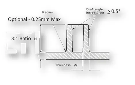
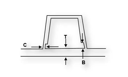
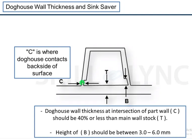
"C" is where the doghouse contacts the backside of the surface
-
Doghouse wall thickness at the intersection of the part wall ( C ) should be 40% or less than the main wall stock ( T ).
-
The height of ( B ) should be between 3.0 – 6.0 mm
OBJECTIVES:
- Create a Screw Boss and Dog House for the Coin Holder following Design Rules for Screw Boss and Dog House creation.
- Use Positioned sketches and the Sketches should be Iso-Constrained.
- To ensure proper tree structure is followed.
- Geometrical sets should have a proper name based on the sketches present inside of them.
- All the sketches should be created under the geometrical set.
- A detailed report should be done explaining the draft analysis and the tooling axis creation.
- An explanation should be given on the way of creating the tooling axis, particularly the Bisecting method.
THEORY:
- Draft Analysis:
Draft analysis helps to detect if your drafted part is easily removable from the mould (in case of plastic component) or die (in case of sheet metal). All plastic components will have a minimum draft of 0.5 to 3deg. And for automotive sheet metal parts, the draft will be 7deg or more. If a mould wall is perpendicular to the part ejection, there is ample friction or interference between the mould and the part which will not allow one to release from the other. This is why design engineers give a minimum draft to the part.
In CATIA V5 the feature draft analysis dialogue box looks like this:
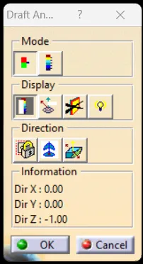
- Mode:
- The mode option let you choose between quick analysis and full analysis mode.
- In quick mode, there are 3 ranges blue, red and green colours. In the case of the plastic component, we will set the draft angle as 3°.
2. Display:
- The first box is to open and close the colour scale dialogue box.
- The second box is the analysis under the running point when activating the checkbOx and moving the pointer over the surface. This option enables you to perform local analysis. Arrows are displayed under the pointer, identifying the normal to the surface at the pointer location (green arrow), the draft direction (red arrow), and the tangent (blue arrow). As you move the pointer over the surface, the display is dynamically updated. Furthermore, circles are displayed indicating the plane is tangent to the surface at this point. The displayed value indicates the angle between the draft direction and the tangent to the surface at the current point.
- Click the No Highlight Representations button to set the display option of highlight effect sources as 'on/off. When checked 'On" the surfaces are selected but they will not be seen in the specification tree.
- Click the Light Effect button and the colours of the analyzed elements react to the light source.
3. Direction:
- The first check box is the locked direction icon which is used to lock the direction of the compass after selecting the specified direction.
- Click on the compass icon to specify the new pulling direction to remove the part.
- Click the Inverse button to automatically reverse the draft direction. When several elements are selected for analysis, the draft direction is inverted for each element when the button is clicked.
- Tooling Direction:
The Tooling Direction is the direction that the mould pulls apart. The mould is built into two separate pieces. You have a Cavity side and you have the Core side. The Core pulls apart from the Cavity and that's the Dyeline or the Tooling Direction. There are different methods to find out the tooling direction. Here we are using bisecting method to find out the tooling direction. We can use any method the ultimate aim is to reduce the cost of manufacturing by reducing the complicity in manufacturing the component.
- Screw Boss Design:
Bosses find use in many part designs as points for attachment and assembly. The most common variety consists of cylindrical projections with holes designed to receive screws, threaded inserts, or other types of fastening hardware. As a rule of thumb, the outside diameter of bosses should remain within 2.0 to 2.4 times the outside diameter of the screw or insert.
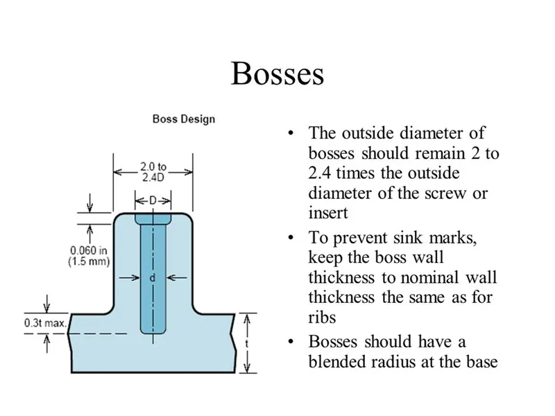
Avoid bosses that merge into sidewalls because they can form thick sections that lead to sinking. Instead, position the bosses away from the sidewall, and if needed, use connecting ribs for support.
Consider using open boss designs for bosses near a standing wall. Avoid bosses that merge into sidewalls because they can form thick sections that lead to sinking. Instead, position the bosses away from the sidewall, and if needed, use connecting ribs for support. Consider using open boss designs for bosses near a standing wall.
Normally, the boss hole should extend to the base-wall level, even if the full depth is not needed for assembly. Shallower holes can leave thick sections, resulting in sinks or voids. Deeper holes reduce the base wall thickness, leading to filling problems, knit lines, or surface blemishes. The goal is to maintain a uniform thickness in the attachment wall Because of the required draft, tall bosses- those greater than five times their outside diameter can create a filling problem at their top or a thick section at their base.
- Design Rules for Screw Boss:
- Draft.
- Thickness.
- Height to Diameter Ratio.
- Optional Radii.
- Boss gussets.
- Coring out the bottom.
- Planning for the type of ejection.
- Screw Boss Thickness (T):
So, one wall (W) will be,
W=0.6* x T
- Measure the base thickness of the rib at the tangent of radius if radii are modelled in
- The larger the area at the base of the rib, the more retained heat.
- The retained heat causes more shrinkage, which causes sinking.
- Measure thickness (T) Boss without Radius:
Measure base thickness (T) where the boss intersects a wall.
- Measure thickness (T) Boss with Radius:
Measure the base thickness (T) of the boss at the tangent of the radius.
- Screw Boss Radius:
Optional Rib fillet radius- 0.25mm maximum.
Must not violate the 40% thickness requirement.
- Screw Boss Draft:
- 0.5 degrees on both inside and outside walls of the boss.
- Different rules if sleeve ejection is used.
- Needs to be planned for.
General Guidelines for Bosses:
- Draft 0.5 degrees on the walls of the boss.
- Thickness- Typically 40% of the nominal wall at the base.
- Height to Diameter Ratio 3:1.
- Radii -0.25mm maximum radii.
- Boss gussets must meet rib guidelines.
- Need to plan for the type of ejection.
- If less than 25mm tall, the draft is not required when sleeve ejection is used.
- Over 25 mm tall, the draft is required on the outside wall only if sleeve ejection is used.
- If sleeve ejection is not used, the draft is required on all walls.
- Doghouse Guidelines:
- Draft.
- Doghouse Walls.
- Part Surface.
- Bottom of Doghouse.
- Wall Thickness.
- Height and Width.
- Doghouse Wall Thickness and Sink Saver:
- Doghouse Width:
- The minimum Doghouse Width (X) for doghouses is 12mm.
- 3:1 ratio of steel width to height. 2:1 is preferred.
PROCEDURE:
- Step 1: Determine Tooling Axis and Side Core Axis:
- Extract the base surface of the Coin Holder and place a point in between the Surface > Point definition select surface > Distance = 0mm and place an Axis system on that point.
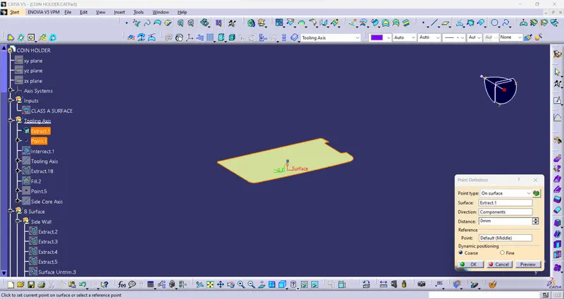
Figure1: Creating a point on the Base Surface.
- With the observation of the Class A Surface, the above which we have created is in the centre of the model and covers major of the parts of the Class A Surface. So we will carry on with the centre point and make a Tooling Axis for the model on the point we have made.
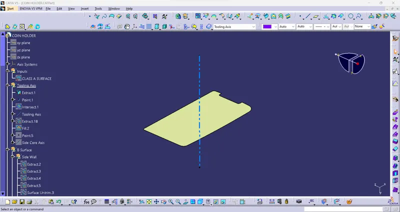
Figure2: The required Tooling Axis for the Coin Holder.
As this model is a little complicated while production we will be requiring a Side Core for this component, hence we will have to make a Side Core Axis.
- The best possible position for the Side Core Axis will be along with the hole in Class A Surface, so let's take the boundary of the hole.
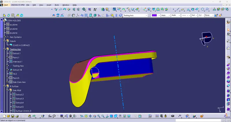
Figure3: Taking the boundary of the hole section in the Coin Holder.
- Now we will fill the boundary of the hole and create a Surface, on the centre of the Surface we will create a point.
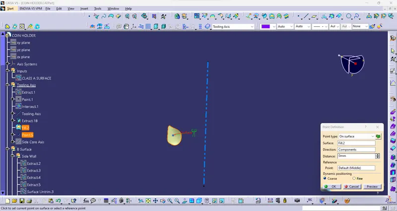
Figure4: Taking the boundary of the hole section in the Coin Holder.
- From this point, we have Created the Surface of the hole part let's make a line which will be our Side Core Axis.
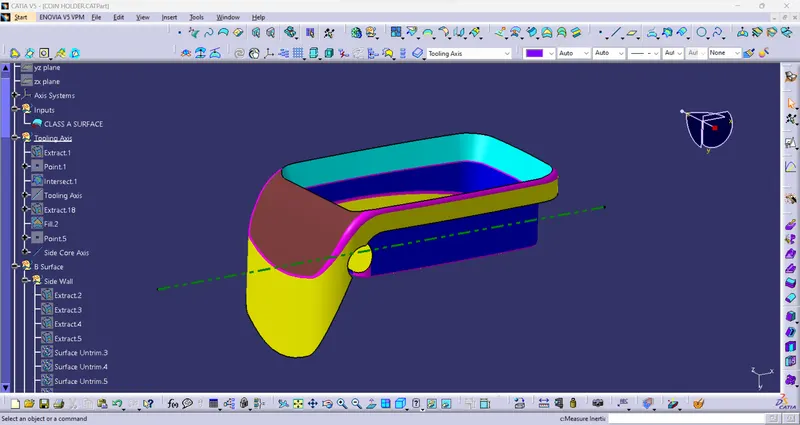
Figure5: The required Side Core Axis for the Coin Holder.
- Now that we have the Tooling Axis and the Side Core Axis, let's publish the Tooling Axis, Side Core Axis and the Class A Surface of the Coin Holder.
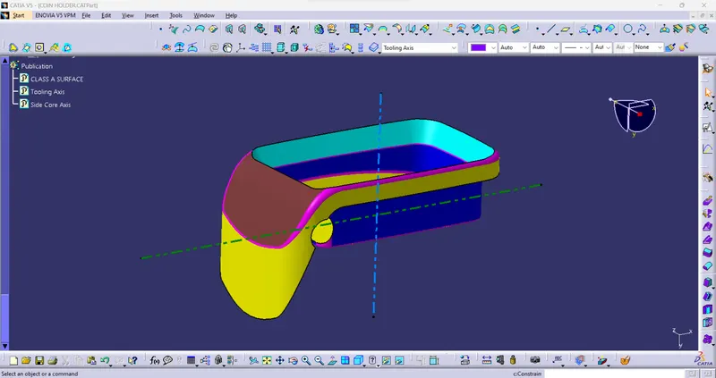
Figure6: Publication of the Tooling Axis, Side Core Axis and the Coin Holder.
Step 2: Creating Dog House for the Coin Holder:
Let's start by creating a Point on the base of the Coin Holder and Extracting the base of the Coin Holder.
- Let's start by creating a point on the Tooling Axis and Extracting the base of the Coin Holder Body.
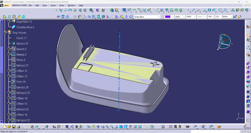
Figure7: Point made on Base and Extracting the Base.
- Now let's make the sketch required for the creation of the Dog House.
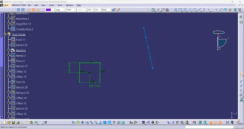
Figure8: Sketch for the creation of Dog House.
- Now let's create a Sweep operation of the sketch we created concerning the Tooling Axis and a Draft Angle of 1.5 deg and to a height of 21mm.
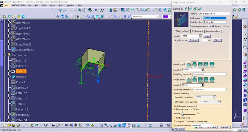
Figure9: Sweep operation on the sketch created.
- Now let's Offset the base Extrude to 20mm so that we can Trim it with the Sweep operation to close the Top part of the Dog House.
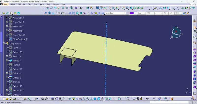
Figure10: Offsetting the base to 20mm.
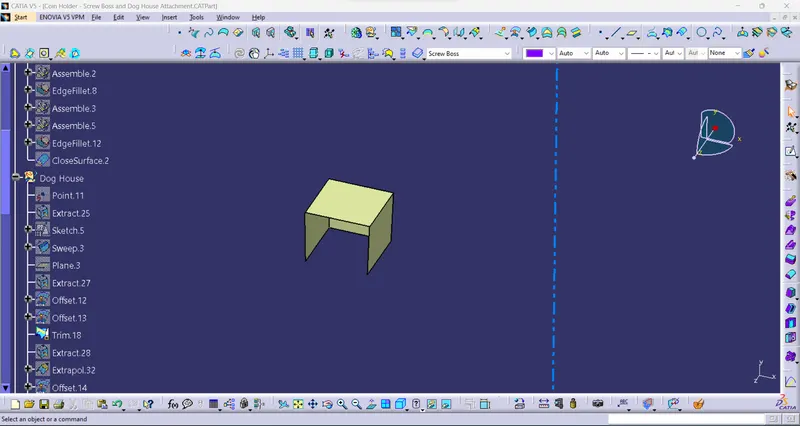
Figure11: Trim output of the Base and the Sweep Operation.
- Now let's convert the Dog House into a solid body for this we will use the Thick Surface operation from the Part Design. We will give it a thickness of 2mm as per the Design Rules.
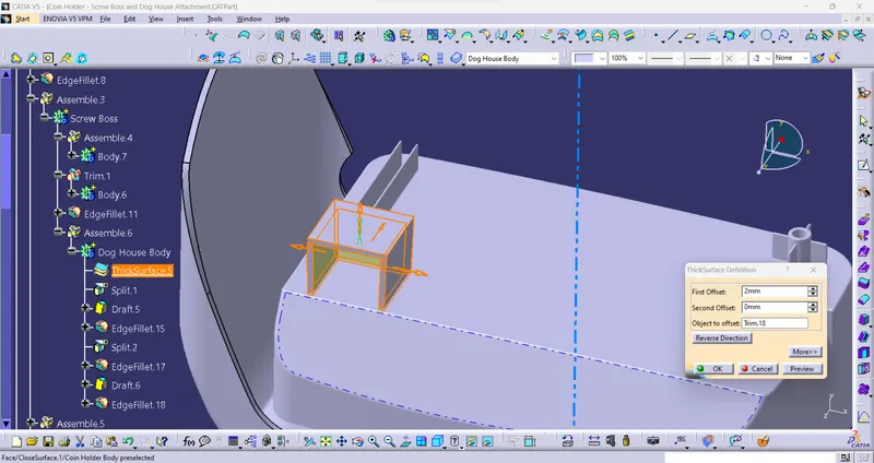
Figure12: Using the Thick Surface operation on the swept component to make a Solid.
- This Dog House need another Side Core Axis for the further operations so let's create that now.
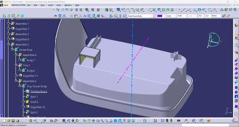
Figure13: Creating a Side Core Axis for the Dog House.
- Let's give a Draft of 0.5 deg to the Dog House we have created. Also, give a Fillet of 1mm to 2 faces of the Extrude.
- Give Fillet to inside as 0.4 x T=0.4 x 2.5 = 1mm and for outer edges give fillet as inside Radius + Part Thickness.
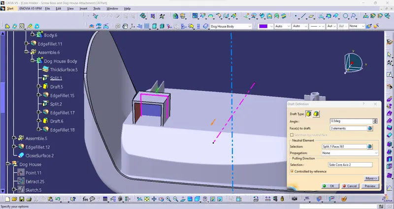
Figure14: Giving Draft to the Dog House.
- Now to create the C and B sections as shown in the Design Rules, Offset the base surface between 3 to 6 mm and Trim it with the Extrude of the Dog House.
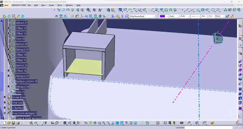
Figure15: Creation of C and B section with above-mentioned operations.
- Switch to the part workbench and Split the C and B sections with Dog House Solid Body. Also, give the Draft of 0.5deg on the Spilted Surface.
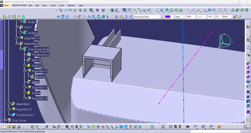
Figure16: Output of Split operation.
- Giving the Outside Fillet as 3mm and Fillet at the B and C section will be 0.5mm.
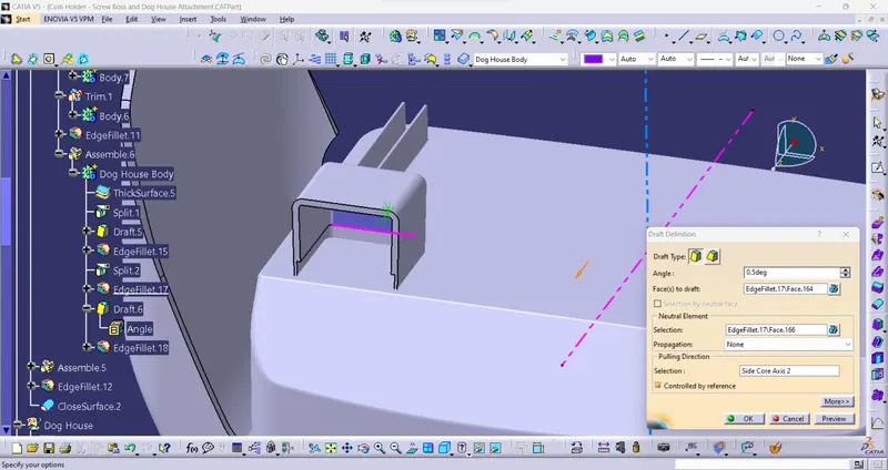
Figure17: Giving Draft and Fillet to the Dog House.
- Now let's Assemble this final Dog House body with the main Coin Holder Body.
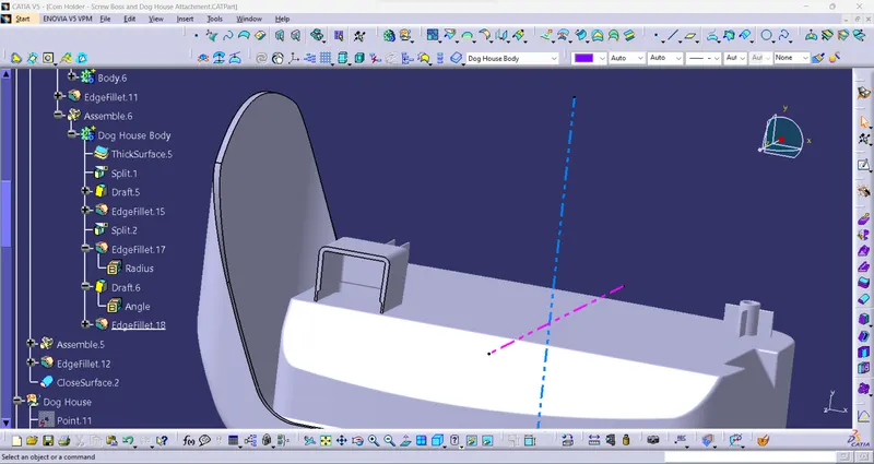
Figure18: Assembling the Dog House with the Coin Holder Body.
- Draft Analysis of the Dog House.
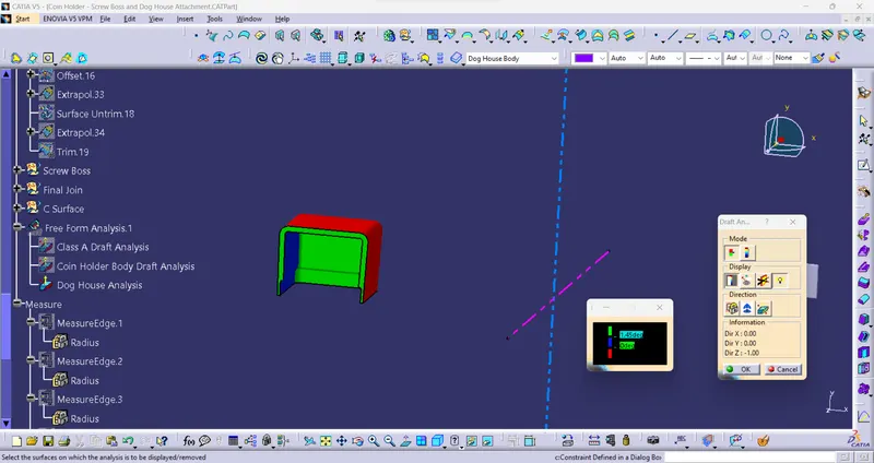
Figure19: Draft Analysis of the Dog House.
- Step 3: Creating Screw Boss for the Coin Holder:
- Let's make the Sketch which is for the Screw Boss.
- Screw Boss can be on Base or it can be on top of the Dog House in this we are mounting it on the Dog House. Draw a circular sketch inside the circle of dia 5mm and for the outer circle wall should be 0.6 x T on one side so outside dia = 2* (0.6 2.5)+5(inside dia)=8mm.
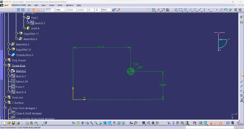
Figure20: Sketch for the Screw Boss.
- Now, let's Pad the Sketch to 12mm and give them a Draft of 0.5mm.
- Pad it with the main Tooling direction considering the height to dia ratio of 3:1.
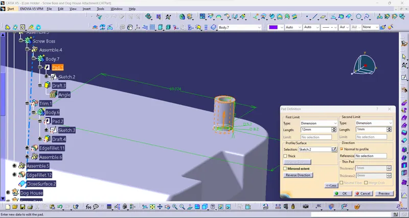
Figure21: Extrude of the Sketch.
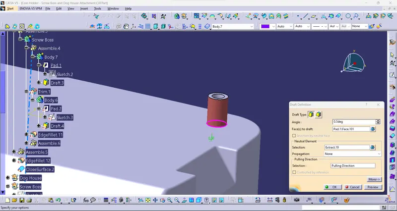
Figure22: Giving Draft to the Extrude.
- Now for the connectors of the Screw Boss let's make the required Sketch.
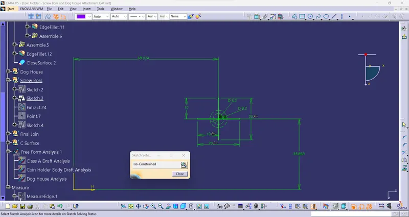
Figure23: Connectors sketch for the Screw Boss.
- Let's Extrude the connectors to 10mm and give the Draft value of 0.5deg to 12 faces of the Screw Boss.
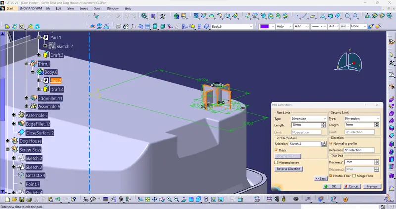
Figure24: Extrude of the Connectors to 10mm.
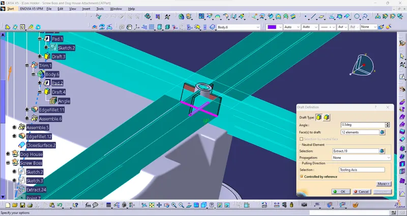
Figure25: Drafting the Connector faces.
- Let's give a Fillet of 0.25mm on 19 faces of the Screw Boss.
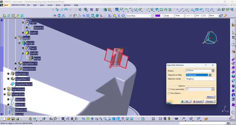
Figure26: Giving Fillte to the Screw Boss.
- Now let's Assemble this Screw Boss to the Main Body of the Coin Holder.
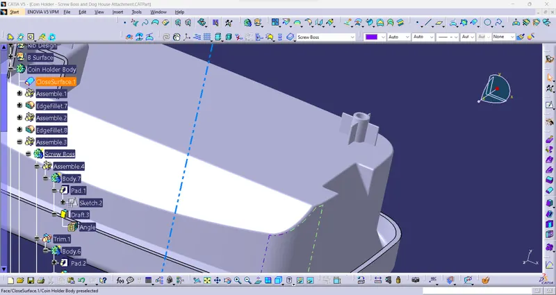
Figure27: Adding the Screw Boss to the Coin Holder.
- Draft Analysis of the Screw Boss.
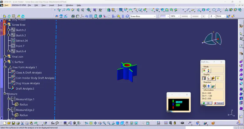
Figure28: Draft Analysis of the Screw Boss.
- Terms asked to Mention:
- Tree Structure:
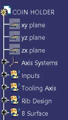
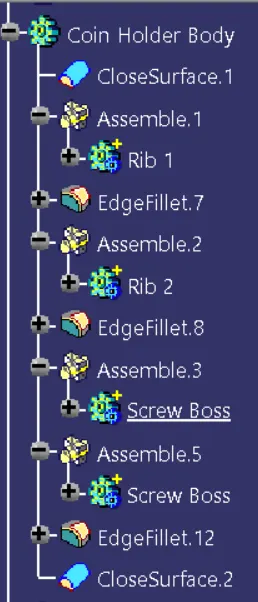
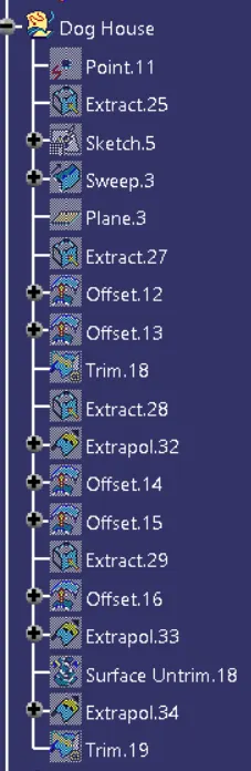
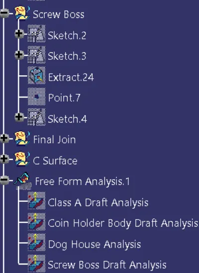
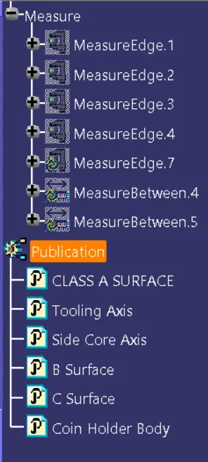
Figure29: Screenshots of Tree Structure of Coin Holder.
- Screenshots of the model with the proper colour code of the draft angle in various orientations (Isometric, Front, Side, and Top View):
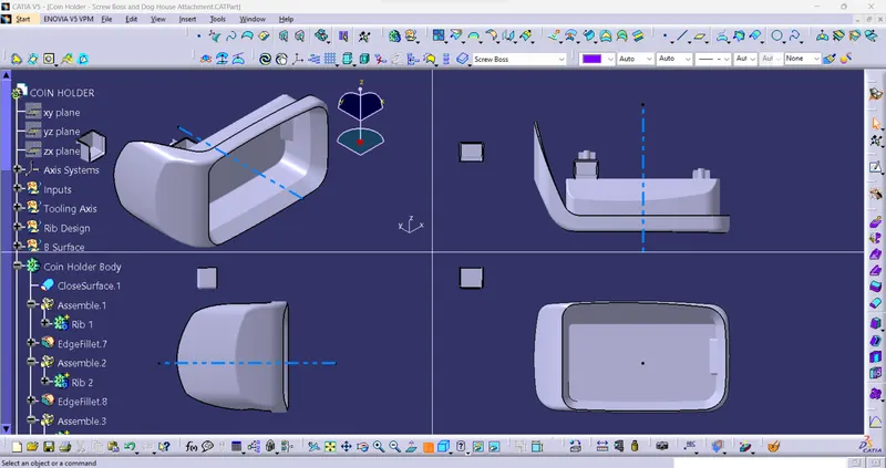
Figure30: Model in Various Views.
RESULT:
- Creation of Tooling Axis and Side Core Axis for the Coin Holder.
Figure31: Result of creating Tooling Axis and Side Core Axis of Coin Holder.
- Draft 0.5 degrees on the walls of the boss.
- Thickness- Typically 40% of the nominal wall at the base.
- Height to Diameter Ratio 3:1.
- Radii -0.25mm maximum radii.
- Boss gussets must meet rib guidelines.
- Need to plan for the type of ejection.
- If less than 25mm tall, the draft is not required when sleeve ejection is used.
- Over 25 mm tall, the draft is required on the outside wall only if sleeve ejection is used.
- If sleeve ejection is not used, the draft is required on all walls.
- The minimum Doghouse Width (X) for doghouses is 12mm.
- 3:1 ratio of steel width to height. 2:1 is preferred.
Figure32: Results of the Dog House and Screw Boss made for Coin Holder.
- Draft Analysis on the Dog House and the Screw Boss.
Figure33: Result of Draft Analysis.
- The Coin Holder Body with Ribs has passed the Draft analysis test as the draft values of the Coin Holder are less than 3° and the Holder is safe for production.
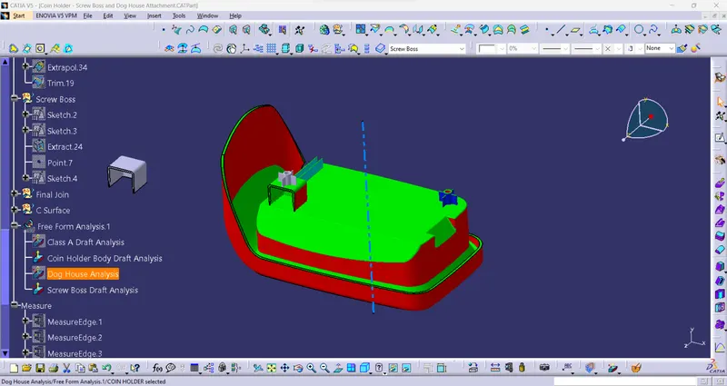
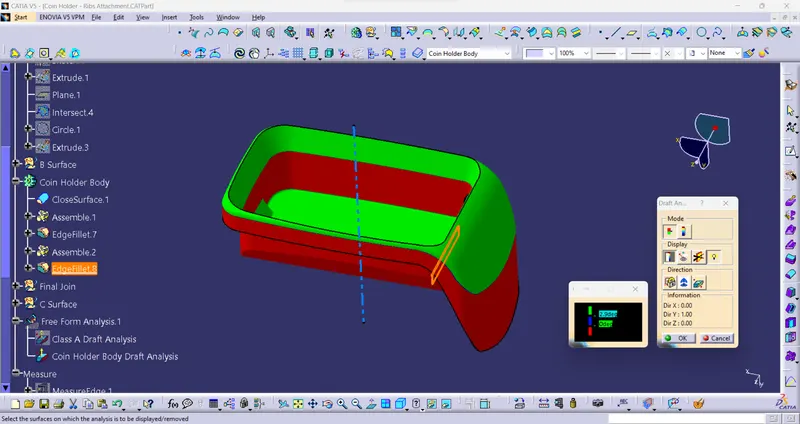
Figure34: Result of Draft Analysis of Coin Holder Body with Ribs.
CONCLUSION:
Creation of Dog House and Screw Boss on Coin Holder has been successfully done by following all the Design Rules and the Tooling Axis has been created following OEM Standards.