Week 9 - Attachment Feature Creation - Challenge 2
AIM:
Design the boss and Dog House for the Centre console coin holder while following the design rules.
OBJECTIVE:
SKETCHES
Make sure to Use Positioned sketch
Sketches Iso-Constrained
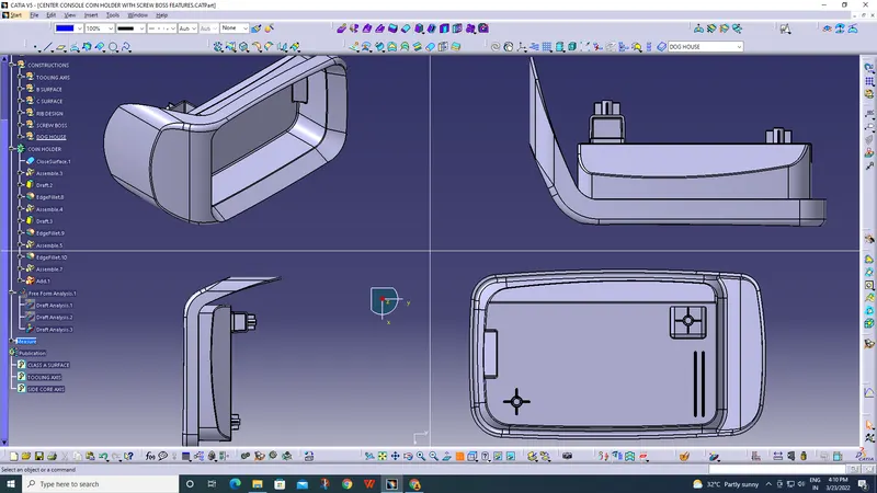
TREE STRUCTURE
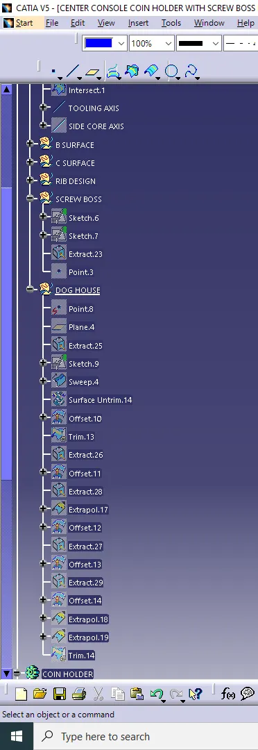
Ensure Proper Tree Structure
Geometrical sets should have a proper name based on the sketches present inside of it
All the sketches should be created under the Geometrical set
REPORT
A detailed report should be done explaining the draft analysis and the tooling axis creation.
An explanation should be given on the way of creating the tooling axis .
INTRODUCTION:
1. SCREW BOSS :-
Injection molding designs, boss features are frequent. They are used to help with the assembling of molded pieces by providing a screw channel.
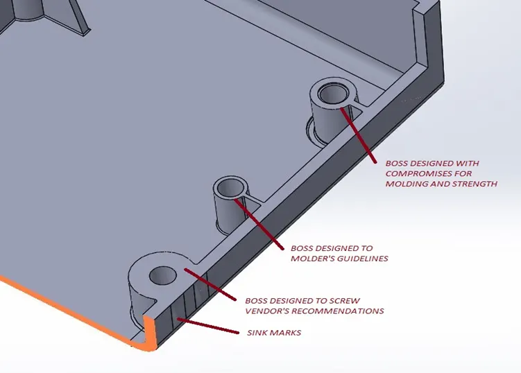
2. DOG HOUSE:
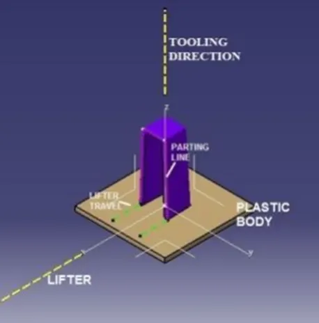
A dog house is an engineering feature used during construction of plastic trim. They serve as supplementary features. Other technical elements like as snaps, locators, and so on are sometimes installed on them to boost their strength.
DESIGN RULES:
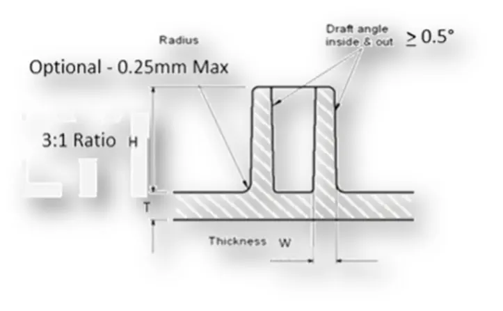
General Guidelines for Bosses:
Draft - 0.5 degrees on walls of boss
Thickness - Typically 40%* of the nominal wall at the base.
Height to Diameter Ratio - 3:1
Radii - 0.25mm maximum radii
"C" is where the doghouse contacts the backside of the surface
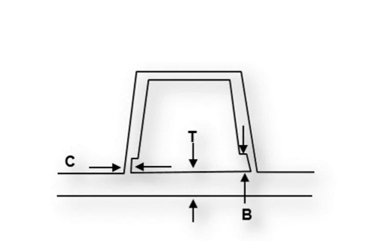
- The thickness of the doghouse wall at the intersection of the portion wall (C) should be 40% or less than the thickness of the main wall stock ( T ).
- Height should be between 3.0 and 6.0 mm.
-The Surfaces Cleared Along The Lifter Axis Have A Minimum Draft As Well.
-The height of the attachment walls should be at least 3 mm.
-This prevents plastic defects on the B side while preserving the texture of the A side.
PROCEDURE:
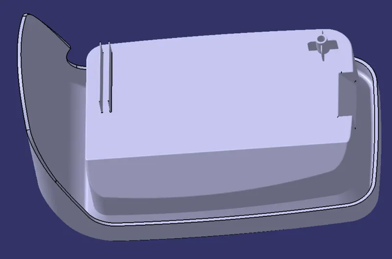
Model of Center Console Coin Holder to make the attachment features on it.
CREATION OF SCEW BOSS:
- Screw bosses can be strengthened with ribs or gussets to increase their strength and longevity. As previously stated, a boss should not be located near outside walls, however
- Coring ribs can be used to maintain it attached to the part's outside wall without risk of sink.
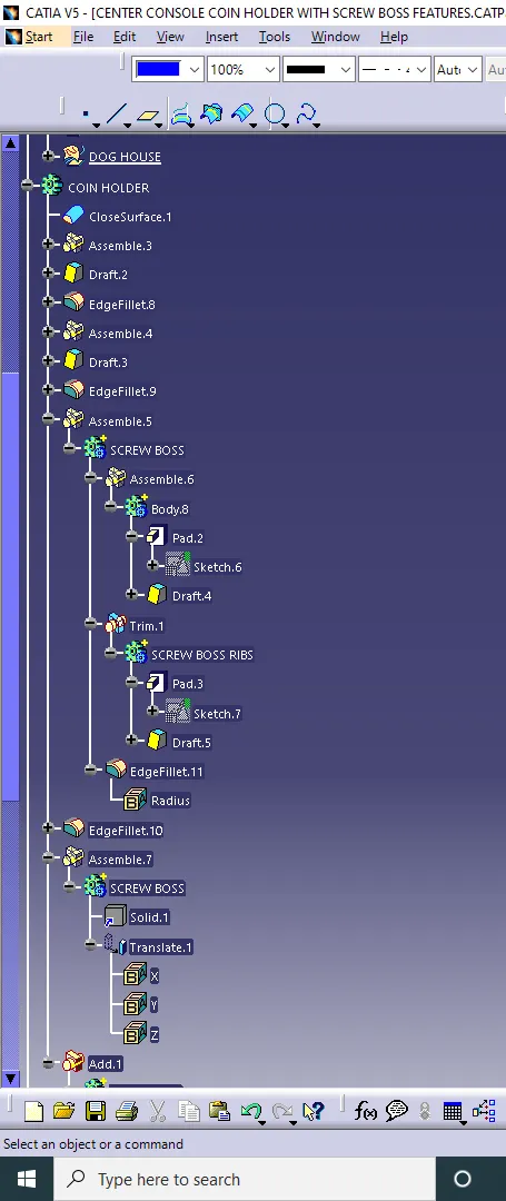
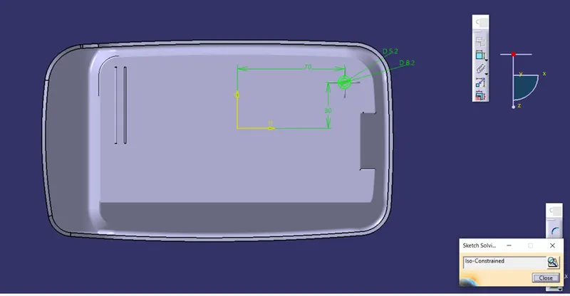
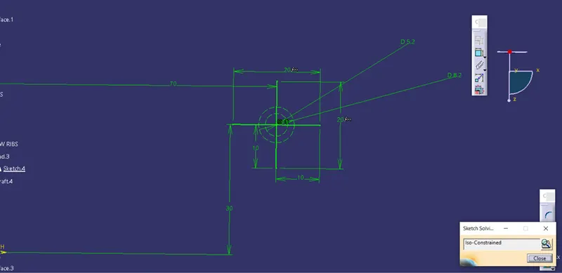
- The first step is to draw a drawing of the Screw boss slot and its ribs in order to reinforce it with Iso-Constrained
- The first step is to draw a drawing of the Screw boss slot and its ribs in order to reinforce them using Iso Constrained.
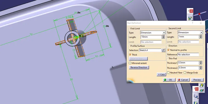
- Then, as illustrated in the photographs below, thicken the sketches by 1mm.
- The screw boss will then be drafted with a minimum of 0.5 degree.
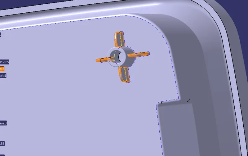
- Then, as seen in the image, use translate to shift the boss so that it may be put on the Dog House.
- Union trim Screw boss and Ribs
- And give required fillets
CREATION OF DOG HOUSE:
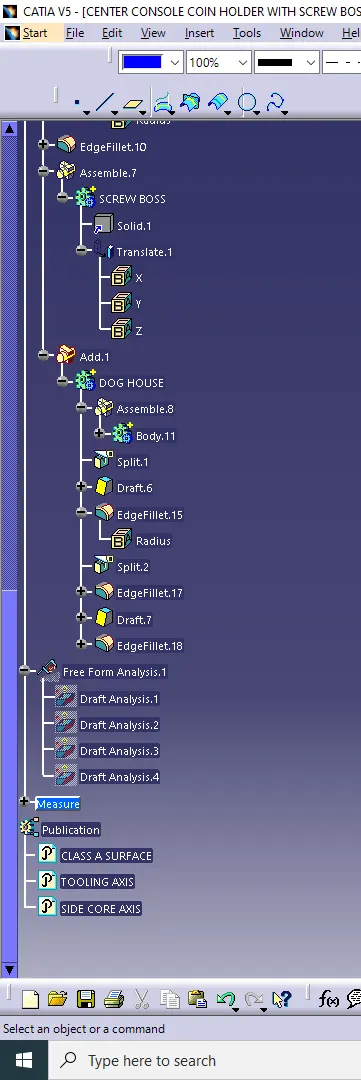
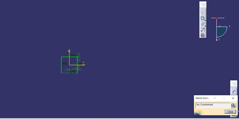
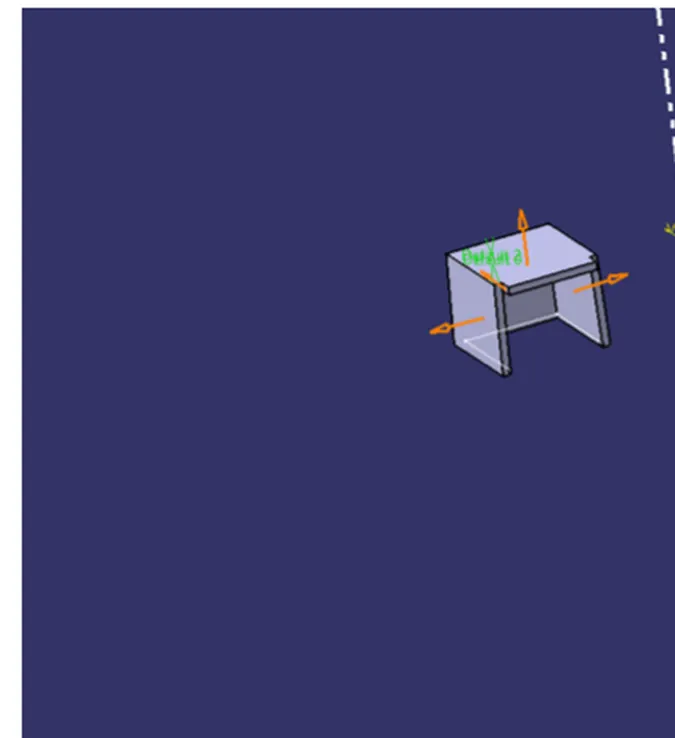
- The first step would be to draw a drawing of the dog home using Iso-Constrained.
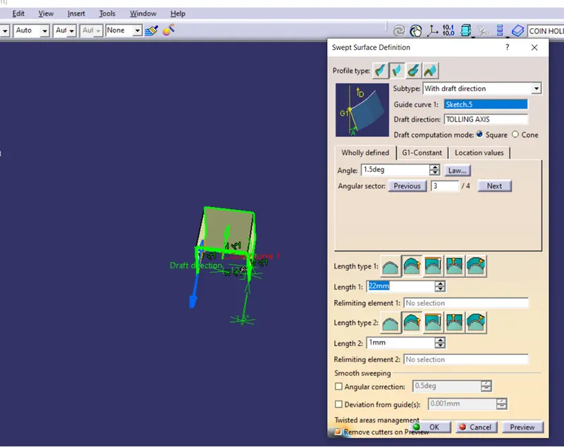
- Create a surface using Sweep.
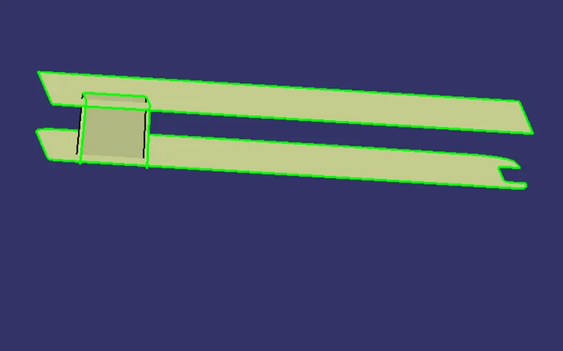
- To build the roof of the dog home, extract the foundation and offset.
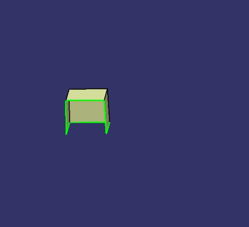
- Thicken the surface with the Pad option.
- The entire technique for making a dog home is depicted in the image below.
- Thick the surface using think feature
UNDER CUT OF DOG HOUSE:
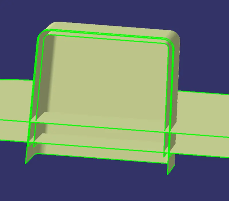
- This is created within the dog home so that the Sink mark and Flow line do not appear on the surface due to the thickness of the dog house.
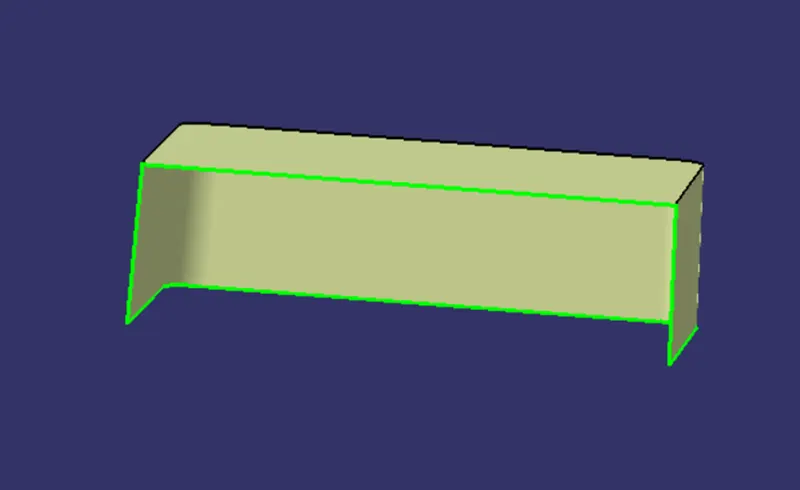
- Extract the Dog House's interior and offset it by 1mm.
- Use the offseted base surface as indicated below to trim.
Draft and Second Dog House:
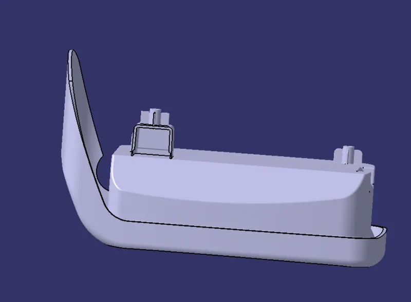
- Minimum draft of 0.5mm for the under cut.
- For the Sceond Dog House use Copy, Paste Special and Rotational Movement along X,Y,Z Axis ( Clockwise and Anticlockwise
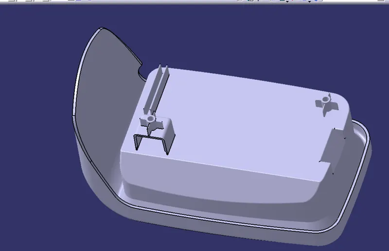
DAFT ANALYSIS:
The finished part is then analyzed to detect if the drafted part will be easily removed from the injection molding.
Draft Analysis option in CATIA is enabled through Insert> Analysis> Feature Draft Analysis
The Draft Analysis Icon has
Mode
Display
Direction.
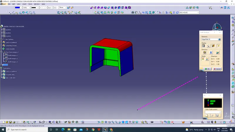
Draft Analysis Procedure:
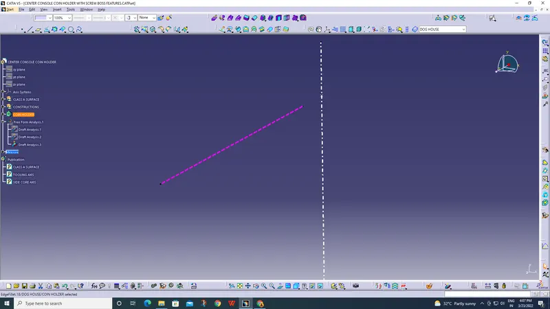
- create new tooling axis for draft analyasis of dog house as name side core axis.
- In the display frame, the produced part must be turned to material mode.
- In the display frame, the produced part must be turned to material mode.
- The axis system is then moved along the direction of the component and aligned with the tooling direction by permitting compass definition.
- After applying Lock Direction, which fixes the compass, the mode dialog box is produced by snapping at any position on the component.
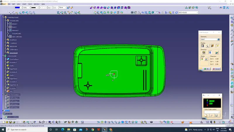
- Color Codes are categorised, and Draft Angle is used.
- The Running point analysis is then used to hover over the component and examine the permitted draft angles before saving the analysis.
DIFFERENT VIEW(ISOMETRIC,SIDE,TOP AND FRONT VIEWS):
TREE STRUCTURE: