Week 9 - Attachment Feature Creation - Challenge 2
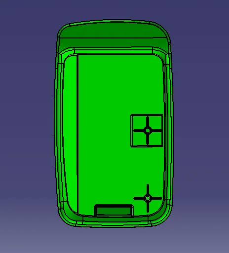
Aim :- To Create the boss and Dog House for the Centre console coin holder considering the design rules mentioned.
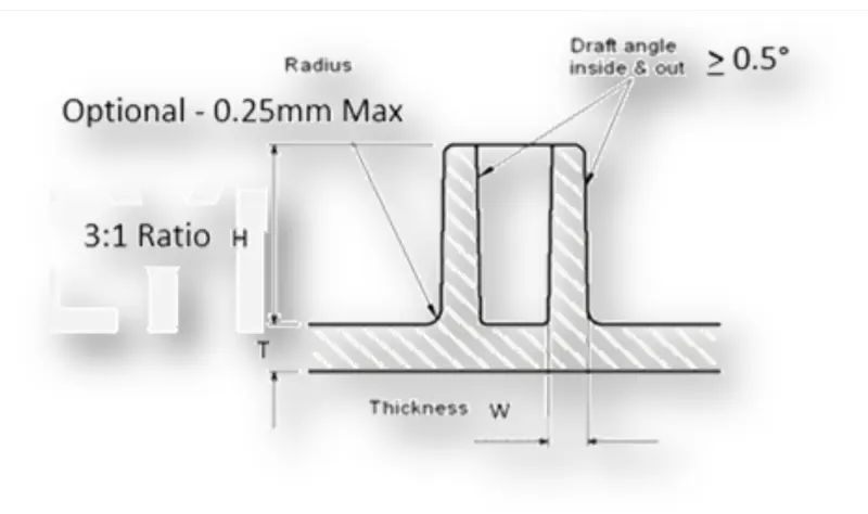
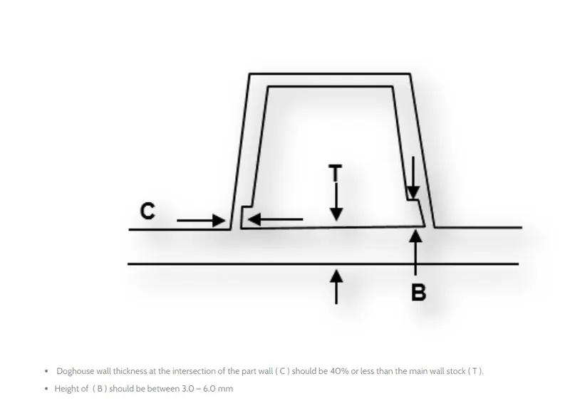
Given design rules :-
Procedure :-
- The given component is a centre console coin holder. screw boss and the dog house is created on the surface below side ie.. class-B. screw boss and the dog house are created for the purpose of screw accomodation and support keeping the plastic design rules.
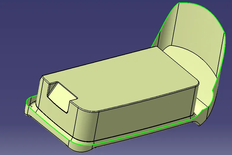
- The surface of the component is extracted. insert a geometrical set and name it as screwboss creation and define it. the extracted surface of the component is taken as base and a positioned sketch is created with projection point. draw circles with outer Radius=4 and inner Dia=5
- Constrain them with the axis created and make sure the sketch is iso-constrained.
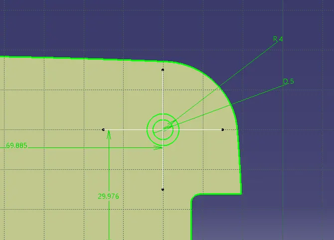
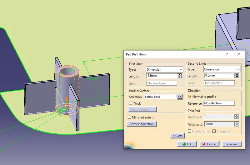
- Now exit the sketch and insert a part body for the screw boss and define it. go to Part body design and pad the sketch with required dimensions. extend the other limit to a bit 0.5mm such that it intersects with the other surface.
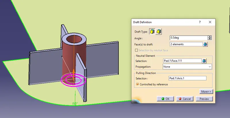
- Now draft the solid created to 0.5 degrees with the base as neutral element in upward direction.
- Now insert another geometrical set and rename it as RIBS and define it. create a positioned sketch with the same projection point and draw the lines for ribs. make sure the sketch is equidistant from the point and iso-constrained.
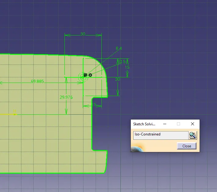
- Insert a part body and rename it as ribs and pad the sketch to certain height and thickness=1mm ( divide the measurement into both the limits) the height of the ribs shouldnt cross the height of the screw boss.
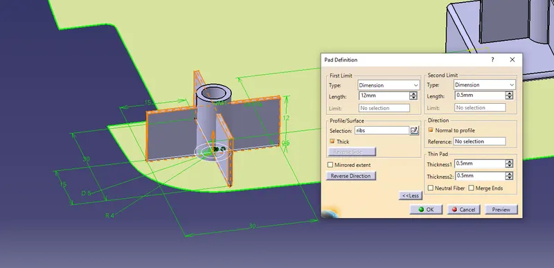
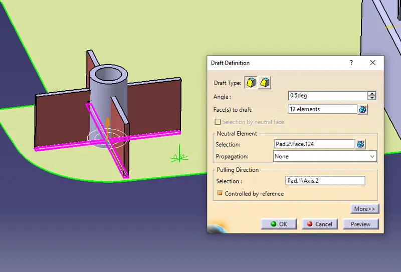
- Draft the ribs to 0.5 degree with the base as neutral element. select all the faces of the ribs.
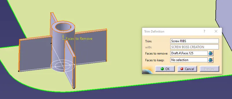
- Since the ribs are intersecting with the screw boss. unitrim the ribs with the screw boss and select the unwanted faces to remove.
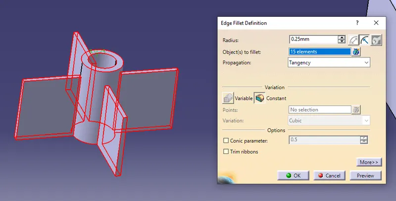
- Add edge-fillets to the ribs and screw parts. select all the surfaces. 0.25mm as fillet radius.
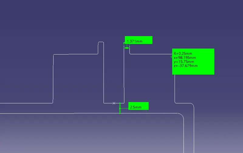
- Now create a plane with parallel to the point created in XY- direction. intersect the plane with the screw boss unitrim. and measure the distances .
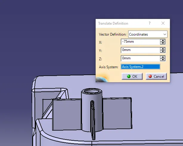
- Now before adding the created screw boss to the main part body, to create another similar part design in another location. copy and paste the screw boss part body and paste specials with the main component. now translate the screw boss in required direction through co-ordinate system.
- Now add the previously created screw boss solid to the main part body using boolean operation (ADD) .
- Now create a dog-house for the screw boss. insert another geometrical set for the dog house creation. and define it. now with the point through the the translated screw boss. create a positioned sketch with point projection and draw the lines such that they are distant from the screw boss . make sure they are iso-constrained.
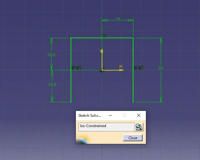
- Exit the sketch and insert a part body for Dog house and extrude it to a height more than the screw boss.
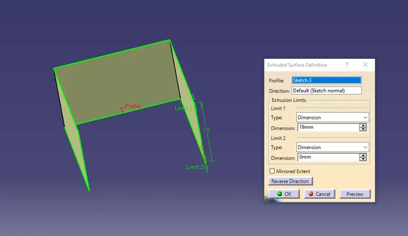
- Now off-set the main surface to the height 1mm less than the extruded surface and trim it.
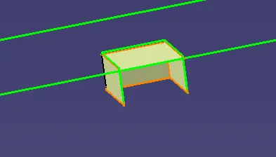
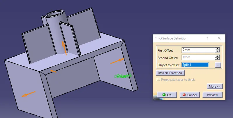
- Now. define the part body and thicken the dog-house surface using thick surface option to 2mm.
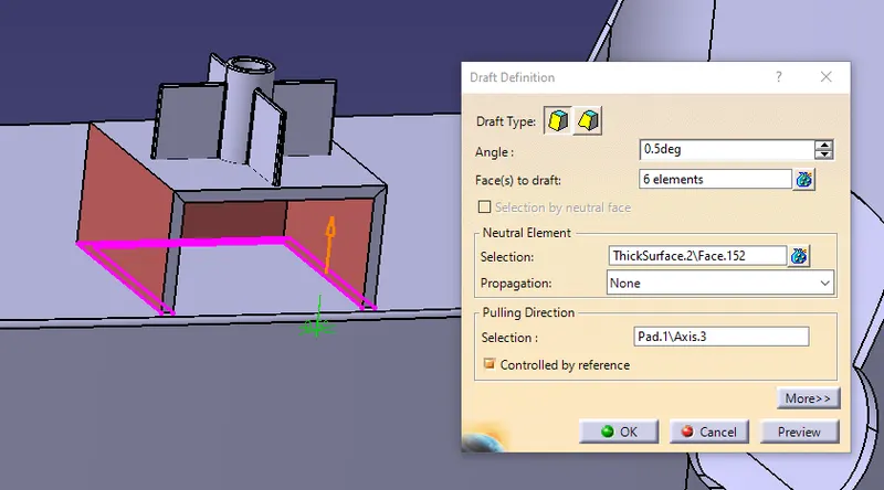
- Draft the thickened surface to 0.5 degrees in the tooling direction.
- Now extract the main surface to 3mm upwards and similarly. extract the inner wall surfaces of the thickened dog house to 0.8mm. extrapolate them so that they intersect properly. now trim them with the 3mm off-set surface
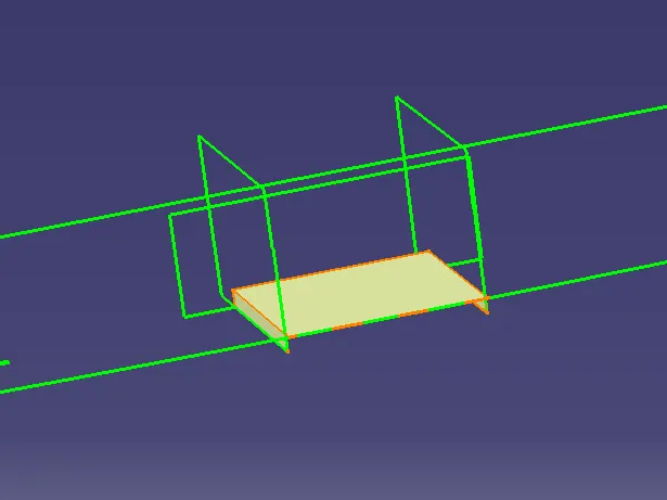
- Now split the created surface with the thickende dog house surface.
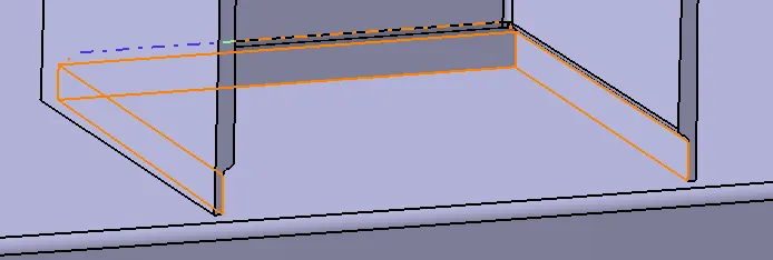
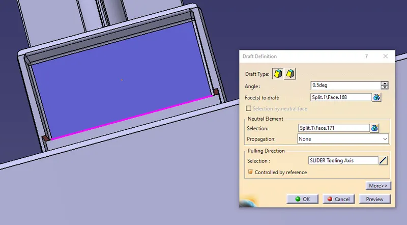
- Now draft the inner surfaces of the dog house to 0.5 degrees. selecting the neutral surface and newly created tooling direction through the point on the surface of the wall.
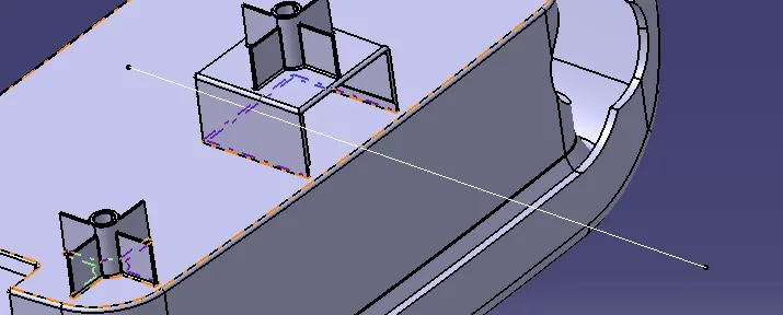
- Add edge- fillets with 1mm outer and 0.5mm inside the thickened surface.
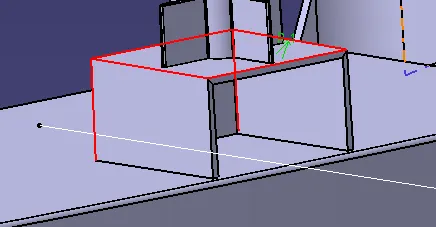
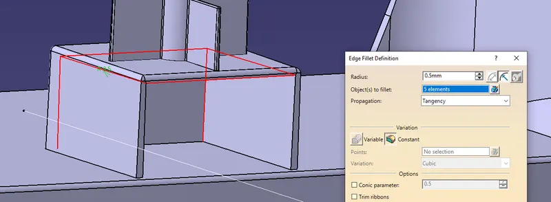
- Now translate the screw-boss with -75mm in Y- direction to place it on to the dog house.
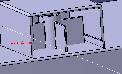
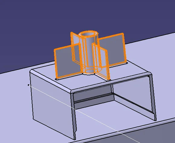
- Now ADD the part body of screw boss to the part body of the Dog house. and similarly ADD the dog house creation part body to the main part body through boolean operation.
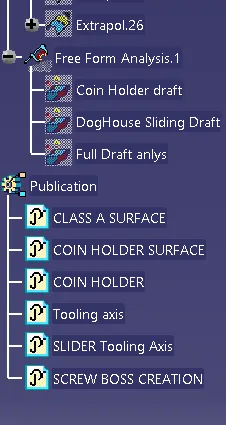
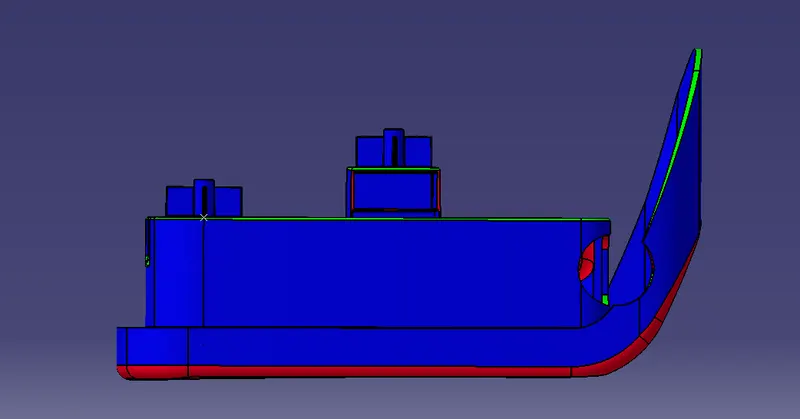
- Now perform the draft analysis to the features created. uhide the main tooling axis and insert feature draft analysis palce the compass on the main tooling axis and select on the whole component. rename the analysis accordingly
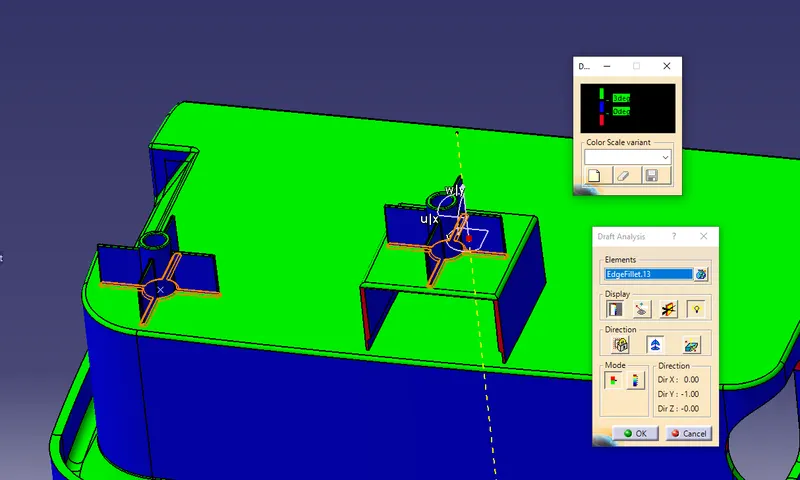
- Since the dog house is having the projection perpendicular to the main tooling axis. the sliding drafting is considered. hence unhide the slider tooling axis and perform the draft analysis in the sliding dirtection.
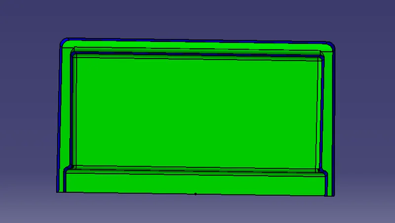
- Insert different geometrical sets and part bodies to easily differentiate them. draft all the required surfaces with the recommended draft angle. fillets rae added after all the operations. also publish the created surfaces and features to easily visualise them in the tree structure.
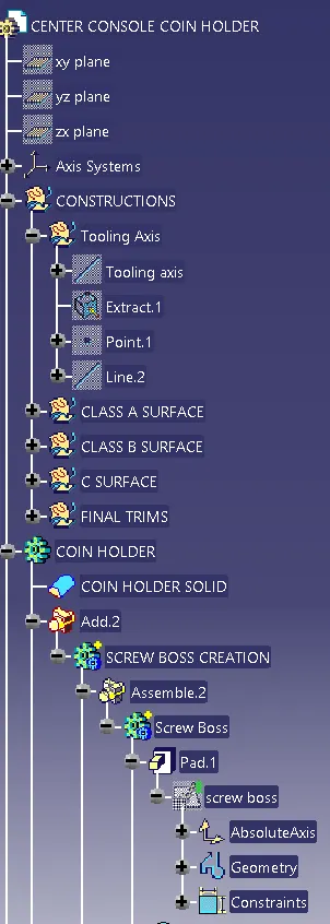
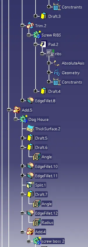
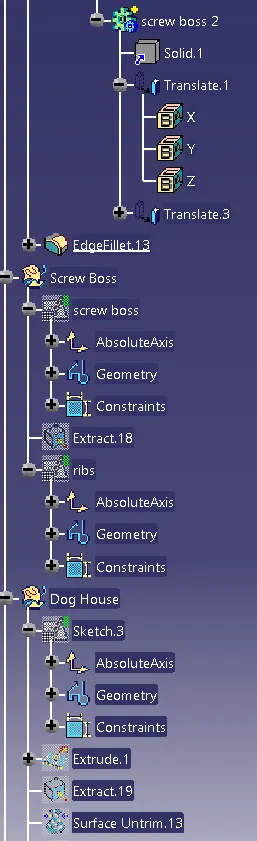
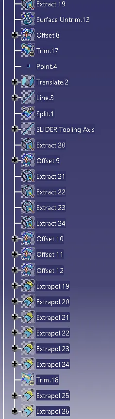
Model tree :-
Result :-
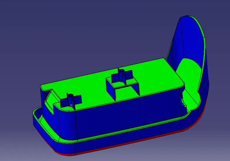
Isometric view -
Front view -
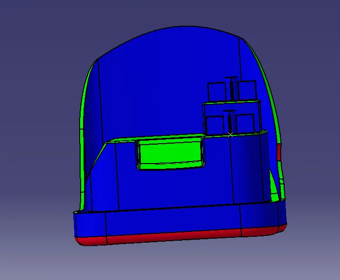
Side view -
Top view -