Week 9 - Attachment Feature Creation - Challenge 2
ATTACHMENT FEATURE CREATION CHALLENGE 2
DESIGN OF THE SCREW BOSS AND THE DOG HOUSE
After the design of the rib on the coin holder our next task is to design the screw boss and the dog house on the coin holder console. We will see the detailed design of both the attachments one by one below.
DESIGN OF THE SCREW BOSS :-
Initially we will design screw boss and then the dog house. So the screw boss is designed as an attachment on to the coin holder in order to avoid the sink marks and also to create the proper attaching space, which indirectly acts as the connector with the other component. The screw boss is the B side feature of the console.
Now whenever any of the plastic product is been designed, some set of the plastic product design rules are taken into consideration.
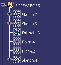
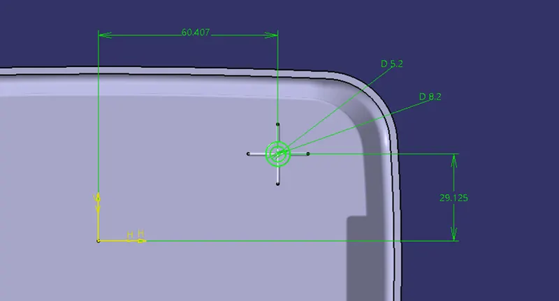
Now to design the screw boss initially the positioned sketch is generated on to the B side i.e the base of the coin holder. Then the two circles are drawn. According to the design rules the outside diameter of the boss should remain 2.0 to 2.4 times the outside diameter of the screw inserted. Here as mentioned in the video the M6 screw is to be designed so the inner hole diameter taken here is 5.2mm. Now to find the outside diameter of the boss so according to the rules we know that,
One wall thickness of the screw = 0.6 * thickness of the component
The above given is the ideal case, but the value can be increased to the requirement to avoid all sink marks and the defects.
So according to the given rule we get,
Considering 2.5mm is the thickness of the component so we get,
2.5 * 0.6 = 1.5mm for one wall thickness
So the outer diameter of the boss will be,
5.2mm the inner hole diameter + 1.5mm per side so it will be,
5.2 + 1.5 + 1.5 = 8.2mm
The outer diameter of the screw boss will be 8.2mm as shown in the figure below.
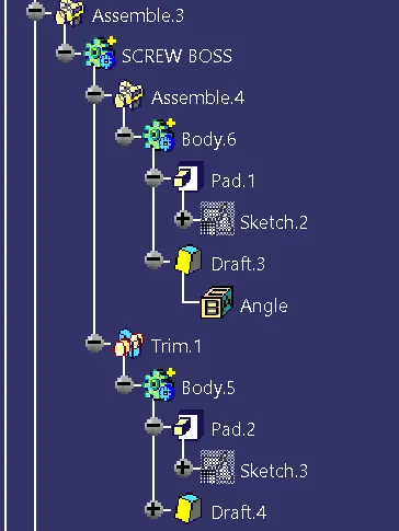
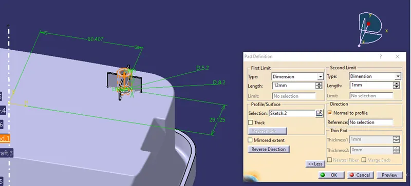
Now this sketch is given pad at a height of 12mm above and 1mm inside the component in order to avoid gap between components. And then the draft of 0.5 degree is provided with the pulling direction as the tooling axis.
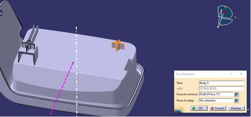
Now to avoid the deformation and to give the maximum strength to the component ribs are added to the screw boss according to the design rules of the ribs. The position sketch is drawn and then it is extruded with the neutral fiber at 10mm and 1mm inside the component. The draft of 0.5 degree is also provided to the ribs. And then finally to add inside the main body, it is trim with the screw boss as shown in the figure below.
The fillet value according to the rule given here is 0.25mm i.e it should not violate 40 % of the thickness. Now the design of the screw boss is completed, it is paste special as a solid and then it is translated diagonally to the opposite direction of the coin holder as shown in the figure below.
Hence our screw boss is fully designed.
DESIGN OF THE DOG HOUSE :-
Dog house is the B side attachment feature that is created to avoid the following things :-
- To avoid sink marks
- To solve the height issue
- To get tooling axis perpendicular to the screw boss.
Now to design the dog house we need to understand some of the plastic product design rules.
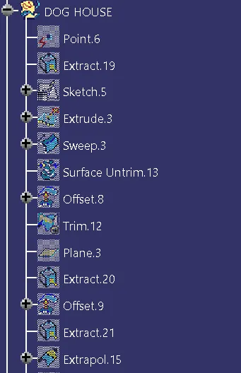
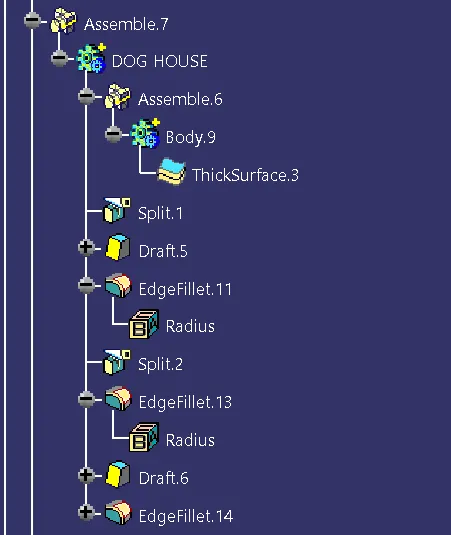
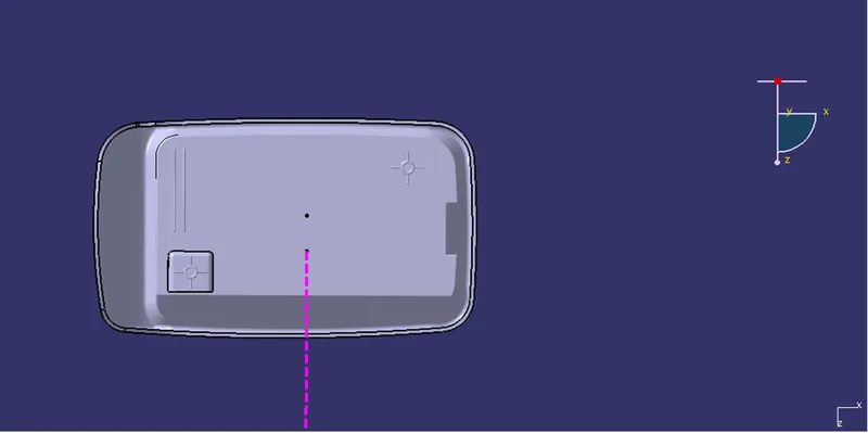
Initially to design the dog house we need to take the point at the base of the second screw boss and then draw a positioned sketch on the extracted surface of the base with the given dimension as shown in the figure below.
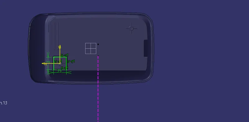
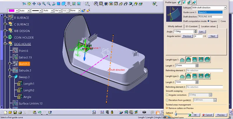
Now as the sketch is drawn, ensure that it is fully constrained i.e iso-constrained and then use the sweep command with the draft direction providing the draft of 1.5 degree and the height of 21mm in the upper side and 1mm in the lower side and the direction of the draft is along the tooling axis as shown in the figure below.
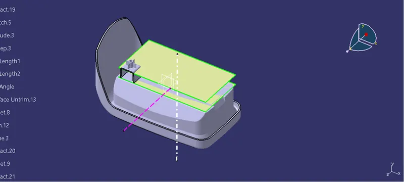
After the sweep then the next task is to close the surface from all the sides. So the extracted base surface is untrimmed and then this untrimmed surface is offset 20mm above the surface as shown in the figure below.
Then the sweep is trimmed with the above offset surface as shown in the figure below.
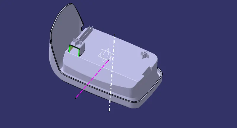
Now the plane is created on the base surface of the coin holder, then the base of the coin holder class A surface is extracted and then it is offset 2.5mm in the upper direction i.e in the outer direction as shown in the figure below.
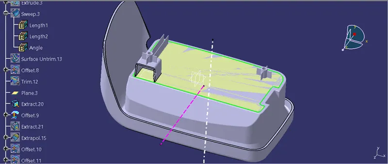
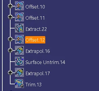
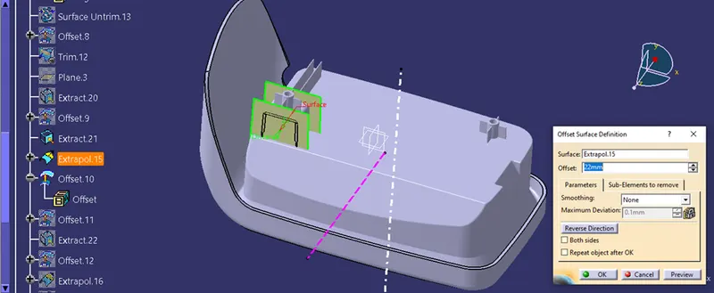
Now the backside of the sweep is extracted and then it is extrapolated with point propagation. Then this extrapolate is offset 22mm in the front direction of the component as shown in the figure below.
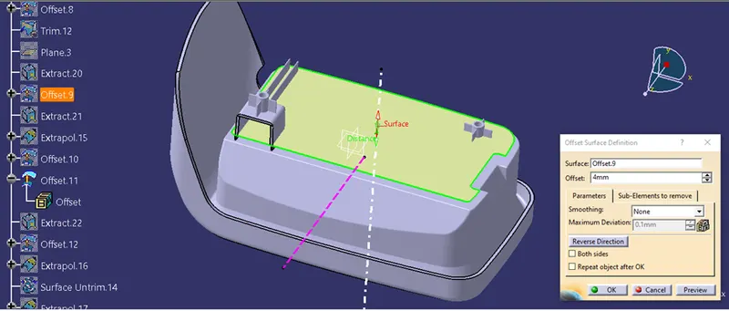
Now as we know that the dog house should have the slot at the base, which should be between 3.0 to 6.0mm. So here the base surface is offset 4mm above in order to create the slot as shown in the figure below.
Now in order to create the perfect design of the dog house the whole inner wall of the component is extracted and then it is offset 1mm in the outside direction, then this offset walls are extrapolated 2mm and then the base surface which was offset 4mm is untrimmed and extrapolated, then the final trim is performed and the required slot is gained.
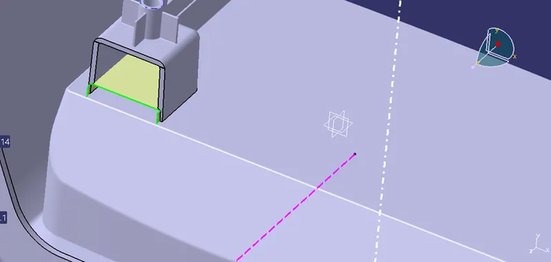
The thickness of 2mm is provided to the component as shown in the below figure. The split command is used reduce 1mm from the front face to the solid body. Actually all this command are used while designing the component. Now all the solid body command are explained one by one. The tooling axis is created which is named as side core axis to clear the inner wall tooling, and the draft angle given to the inner three walls are 0.5 degree with the normal face as the back face and the side core axis as the pulling direction as shown in the figure below.
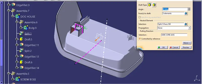
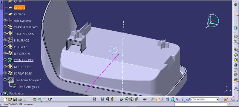
The pink color line is the tooling axis i.e the side core axis.
Now finally the fillet is provided to the inside and outside walls of the component. The inside wall thickness is given as 0.5mm and the outside wall thickness is given as 2.5+0.5 = 3mm. And finally the screw boss that is inside the dog house is shifted above the dog house using the translate command and hence our design of the dog house is full completed as shown in the below figure.
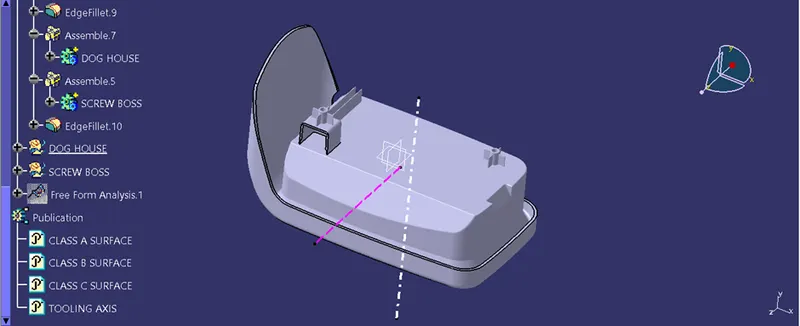
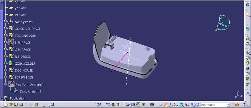
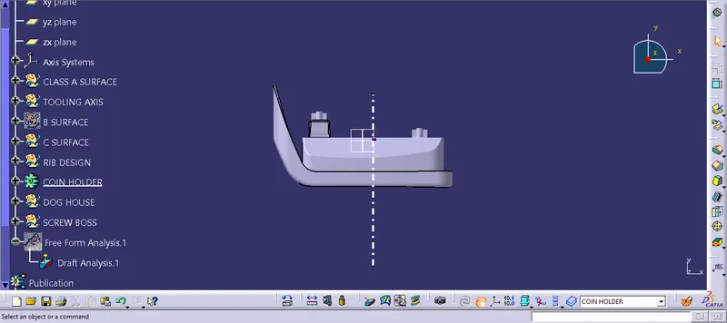
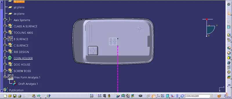
Now the final step the draft analysis is to be done on the dog house so the analysis command is turned on, the compass is kept on the tooling axis the draft angle of 0.48 degree is given as we have given the draft of 0.5 degree. So hence the draft analysis works and don’t show any error so our designed component can be manufactured. This same procedure is done with the side core axis and it also clears the draft analysis and hence the designed is fully done along with the draft analysis as shown in the figure below.
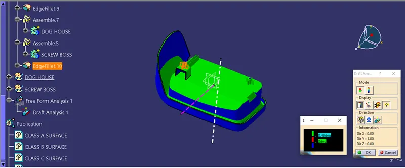
The tooling cleared with the main tooling axis of the component.
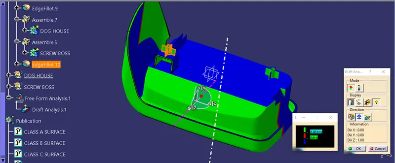
The tooling cleared with the side core axis of the component.
IMAGES :-