Week 9 - Attachment Feature Creation - Challenge 2
FEATURE ATTACHMENT CREATION USING CATIA V5
OBJECTIVE: The main aim of this challenge is to create a screw bosses as well as dog house on a coin holder solid body which is previously designed and to perform a draft analysis on the final solid body with the dog house and screw bosses and to prepare a detailed report explaining all the procedures we have followed and to perform checks to make sure the design is satifying all the required considerations of design.
INTRODUCTION
DRAFT ANALYSIS:
Draft analysis is a analysis which is performed on the objects or bodies in order to check the draft angle of various faces in a particular direction which is tooling direction.
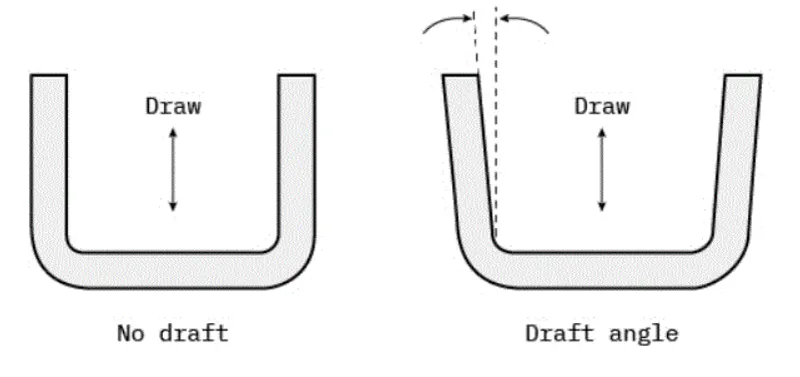
Every part like sheet metal parts which are generated from a Press Tool or some forming tools, may be the plastic parts which generally come out from the plastic moulds and maybe the casting parts, all such kind of parts required some drafted face on the surfaces which are parallel to the tooling direction. If we don't provide drafts on the surface then it will stick to the mould surface and whenever the mould is in motion they will destroy the surfaces or also reduced the finishing of surfaces.
The Tooling Direction is basically the direction that the mold pulls apart. The mold is built in two separate pieces, basically. You have a Cavity side and you have the Core side. The Core pulls apart from the Cavity and that's the Dyeline or the Tooling Direction.
And the axis which represents the tooling direction is called tooling axis and selection of this is axis is a crucial step while performing the draft analysis.
SCREW BOSSES AND DOG HOUSE
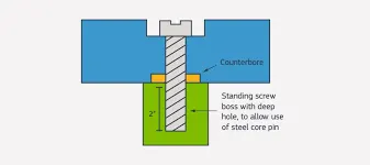
SCREW BOSSES: Boss features are commonly found in injection molding designs. They are used to aid in the assembly of molded parts by providing a channel for a screw. You will want a thick enough wall so that the screw can engage with the plastic without splitting the post.
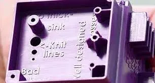
DOG HOUSE: Dog house is an engineering feature used in plastic trim design. Dog houses are used as supporting feature. Sometimes other engineering features like snaps; locators etc. are mounded on them to increase their strength. Dog houses are subjected to draft analysis to prevent breakage of the component during ejection from mould cavity. Dog house and other engineering components are built on B-surface.
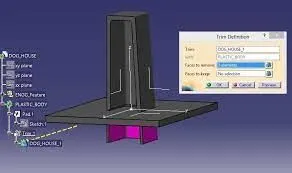
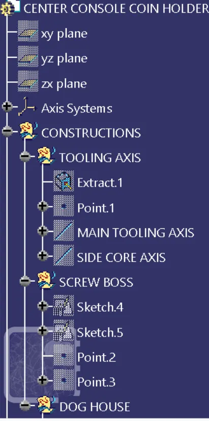
CREATION OF TOOLING AXIS
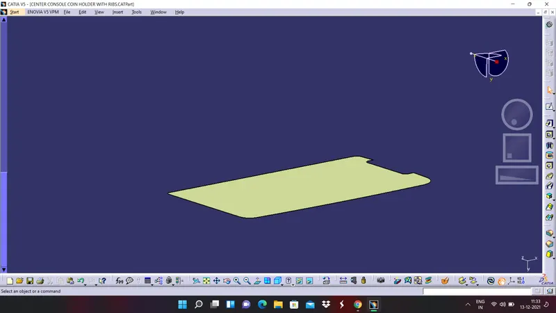
1. Extract the base surface of the the coin holder solid body.
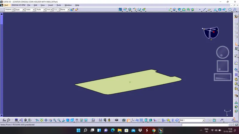
2. Create a point and it should be at the centre of the surface.
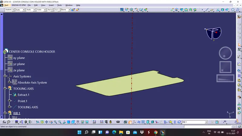
3. Create a line by using line command and selecting point and direction as the line type.
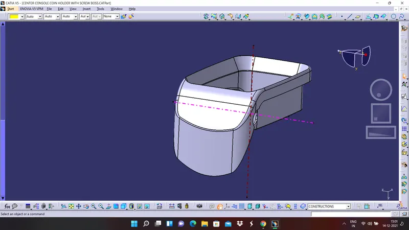
4. Now by using the same point create a line in Z direction and rename the line as side core axis. Since the doghouse cannot be created by using main tooling axis we have to use this side core axis.
CREATION OF SCREW BOSS
1. Create a sketch on the face on which we are lanning to create a screw boss.
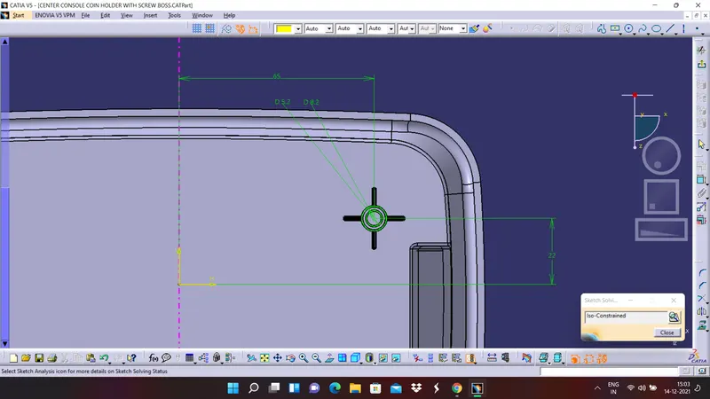
2. Now by using pad command extrude the sketch to a required distance
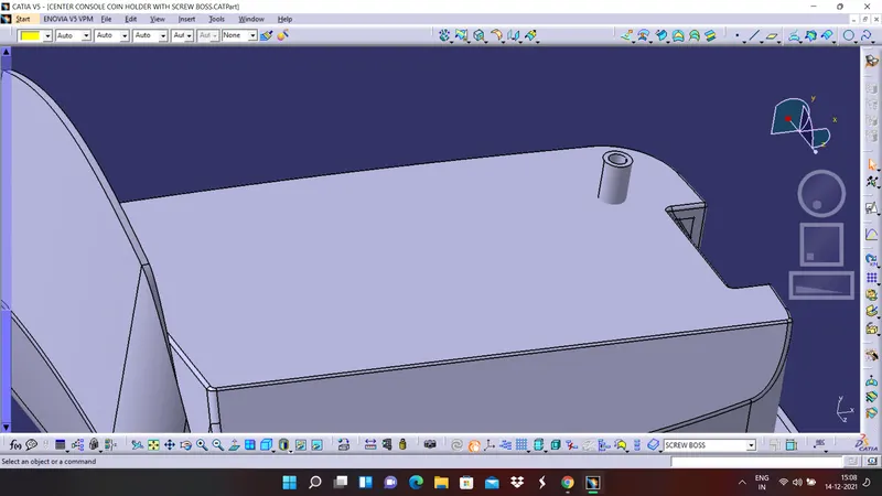
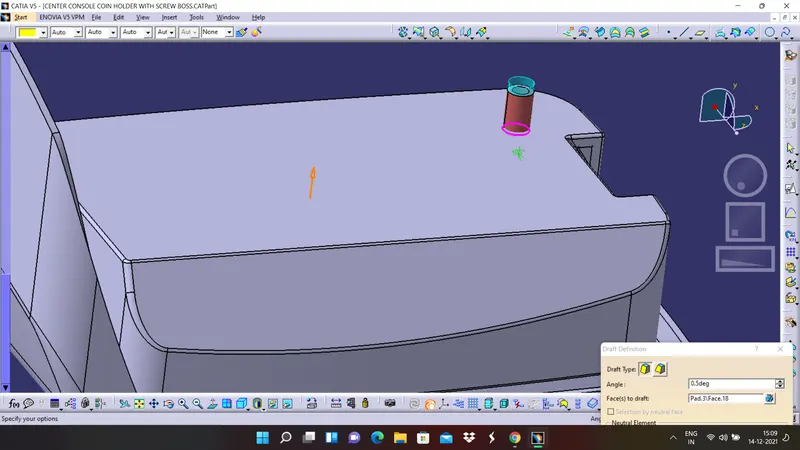
3. Draft the surface with draft angle of 0.5 degrees.
4. Create a sketch as for ribs and make sure the sketch is iso-constrained
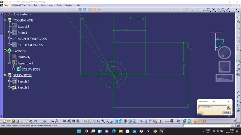
5. Extrude this sketch also to a requited distance and draft the faces to a required angle
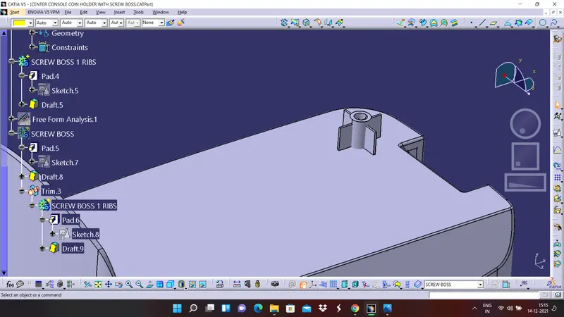
6. Finally trim this with the screw boss surface and union trim them together and add them to coin holder body.
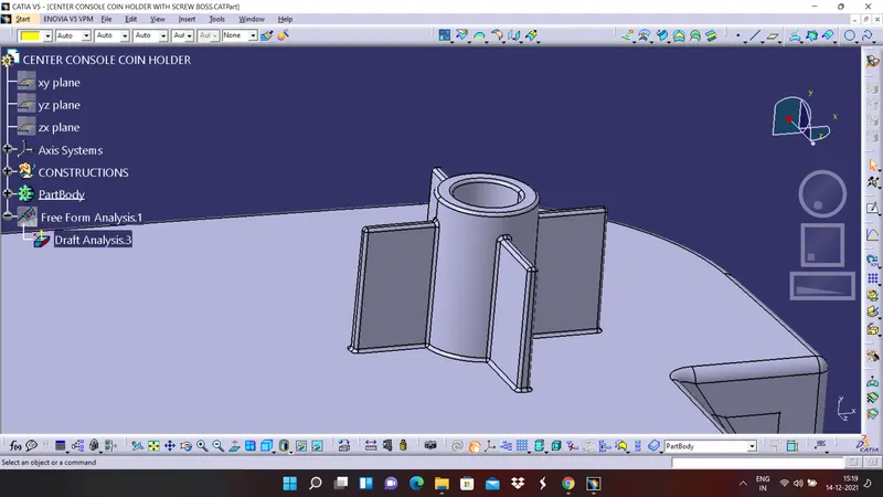
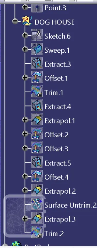
CREATION OF DOG HOUSE
1. Draw a sketch for the dog house on the same plane as the screw boss
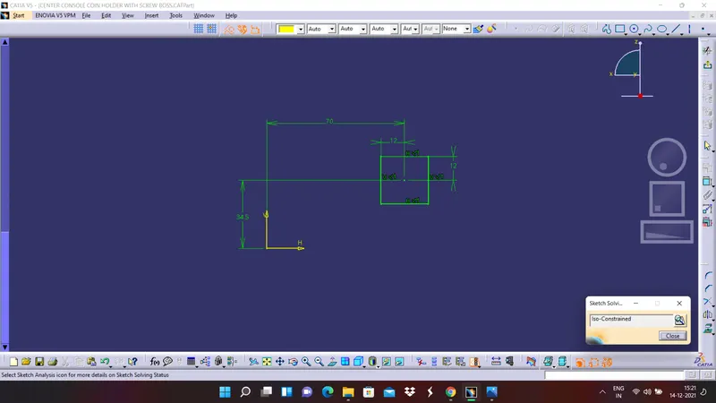
2. Sweep the sketch by providing required draft angle in proper direction
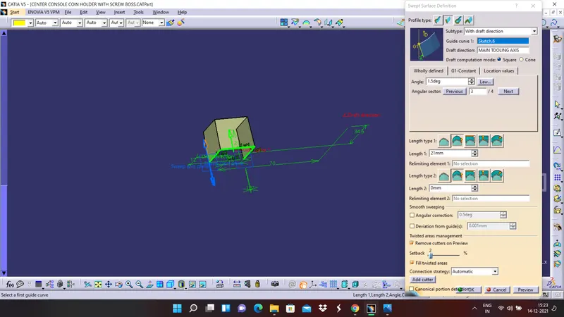
3. By using thick surface command in part workbench give some thickness to the sweep surface,
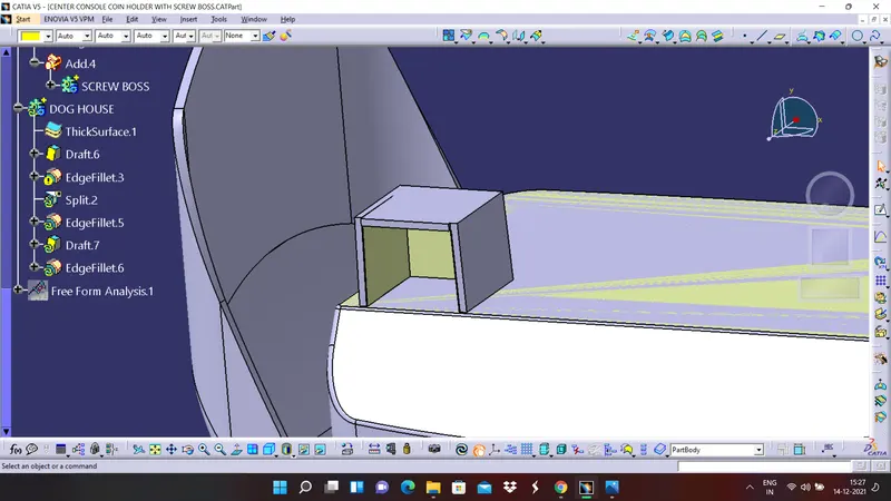
2. Now split the surface to the required direction and give draft angle to it.
3. now by off setting the bttom extrude to 4 mm distace trim the two surfaces and again split it with the dog house body.
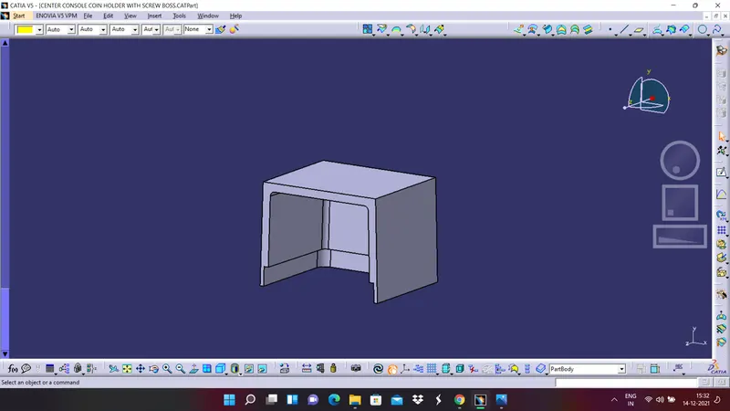
4. Give draft to the inside faces and apply edge fillet every where required with proper raduis. the final dog house as looks as shown in below figure.
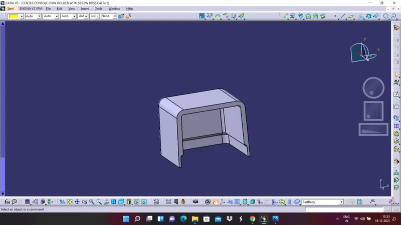
5. Finally add this dog house to the coin holder body.
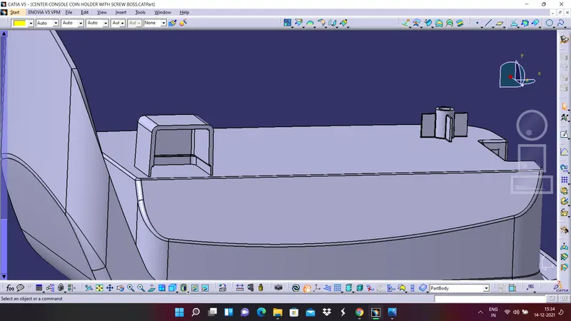
CASE STUDY : In dog house we have given a draft of 1.5 degrees to the outside faces an only 0.5 degrees to the inside draft faces this is because if we give 1.5 degrees for inside faces then the material will become over thick and it will cause difficulty in manufacturing. To simplify this problem we have given 0.5 degrees draft to the inside faces.
CREATION OF SECONG SCREW BOSS
1. First copy the screw boss part and paste it in the main coin holder part.
2. create two points on the screw boss and dog house surface.
3. By using translate option in solid part workbench translate the newly created screw boss and then add it to the solid body.
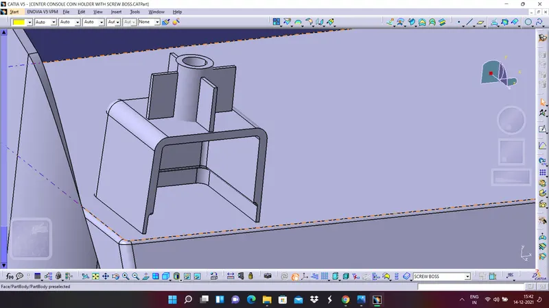
4. Finally apply edge fillet to the the new screw boss and save the file
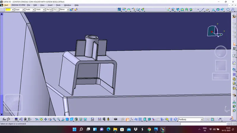
FINAL VIEWS OF COIN HOLDER WITH DOG HOUSE AND AND SCREW BOSSES
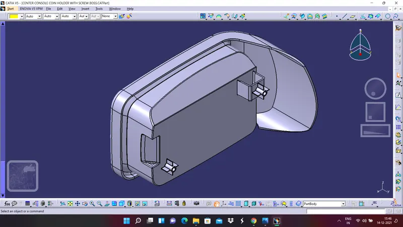
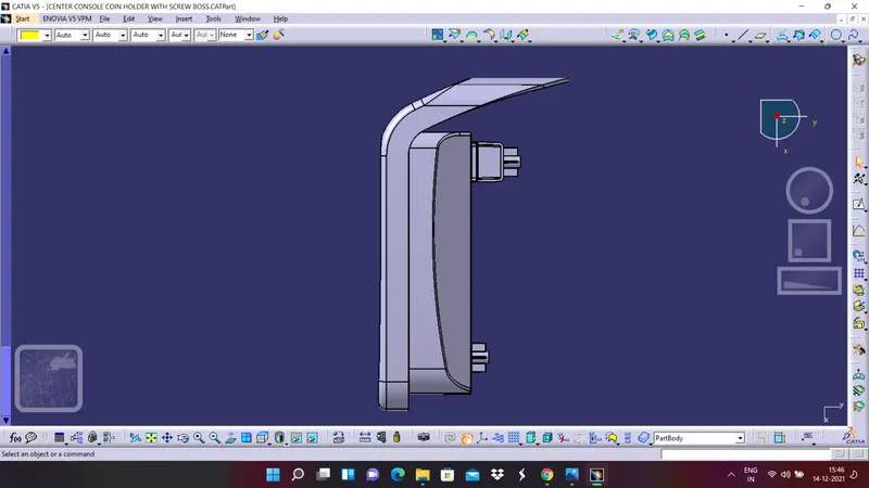
The final views of the coin holder body after creating the dog house and screw bosses are shown in below figures,
ISOMETRIC VIEW
FRONT VIEW
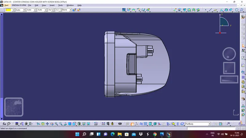
SIDE VIEW
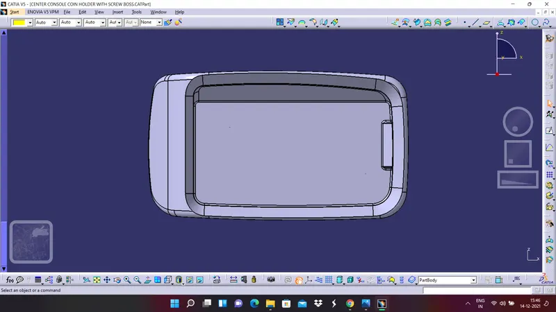
TOP VIEW
PART NAVIGATORE
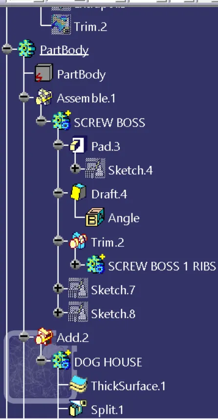
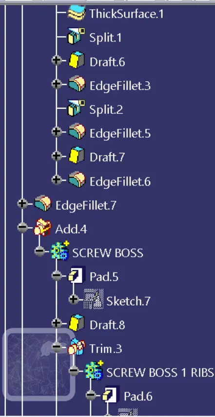
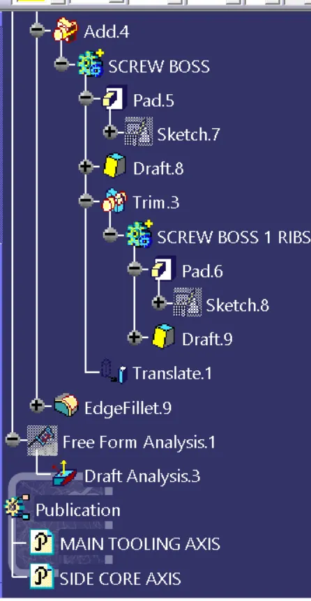
DRAFT ANALYSIS ON FINAL COMPONENT
In this case we have to perform dtaft analysis by using three different angles by using different tooling axis.
1. In first draft analysis we will take 3 degrees as the draft angle and tooling axis as the main tooling axis.
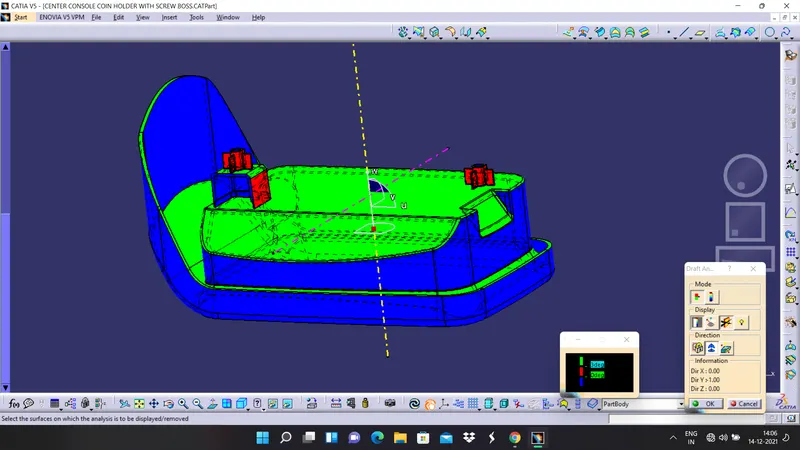
In this we can observe that the main coin coin holder body is clearing the draft analysis.
2. Now we will perform the draft analysis by taking draft angle as 1.5 degrees and we will see if the outer faces of dog house or clearing or not.
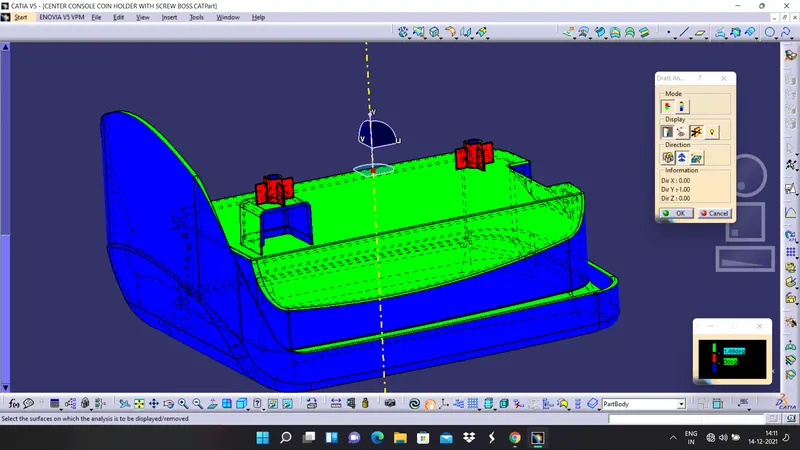
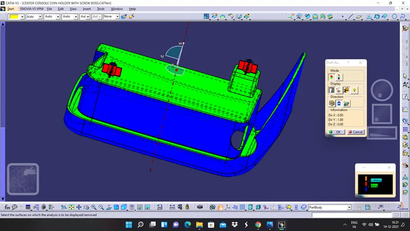
If we observe clearly the intended faces which are outer faces of the dog house are clearing the draft analysis.
3. Now we will give the draft angle 0.5 degrees in main tooling axis and observe how the screw bosses will behave.
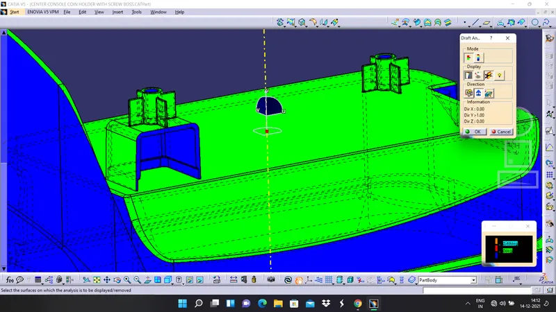
4. Now with the same draft angle and using different tooling direction which is the side core tooling axis and observe the colour codes of inside faces of dog house
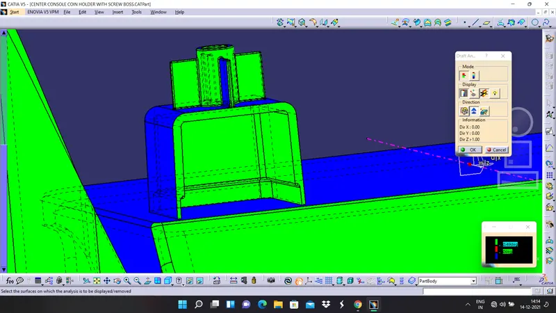
And with that we can surely say that the part which we have designed is satisfying all the design rules as well as it is clearing the draft analysis for respective tooling axis and respective degrees of draft.
CONCLUSSION
Hence we are concluding that the screw bosses and dog house has been designed by following the design rules properly and draft analysis is performed on the final component it is satisfied all the conditions. A detailed report has been prepared and attached to the challenge properly.