Advanced Sheet Metal Design Using NX Cad Challenge_5_Odd Shaped Enclosure
ODD ENCLOSURE IN NX
OBJECTIVE: The main objective of this project is to create or design a sheet metal odd shaped enclosure from a solid body using sheet metal from solid body command in the NX11 application or software and to make us more familiar with the shhet meta from solid body command available in NX11
INTRODUCTION
The Siemens NX is also known as Unigraphics NX is an advanced high end CAD/CAM/CAE software package originally developed by UGS corporation, but since 2007 it is owned by Siemens PLM software.it is used to tasks such as design, engineering analysis, and manufacturing finished design by using included machining module.
NX11 introduces capabilities for convergent modelling, rapid manufacturing, improved annotations, drafting, and documentation and rendering. active workspace in NX11 is build around these items to provide seamless access to PLM capabilities right within NX.
NX sheet metal provides set of tools within the NX design environment that allows simple and fast design of sheet metal parts dependent on material and manufacturing processes, the most common of which is straight brake metal forming.
The NX advanced sheet metal is now the product to choose for creating aerospace parts. typically the aerospace sheet metal parts have planar tabs and webs, with the flanges offset from the airfoil skin. using the advanced flange the tabs and webs are automatically trimmed and flanges added as a reference to the airframe or wing's skin.
DESIGN METHODOLOGY
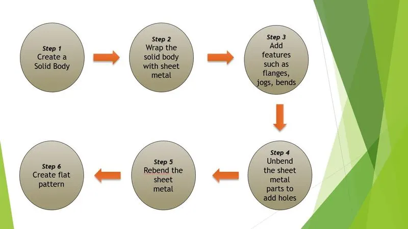
Under the design methodology or design approach section we will discuss about the commands and procedures that are followed to create a sheet metal odd sahped enclosure in the NX 11 with the help of a flow chart. the flow chart gives us a clear cut idea about the procedures followed whilw designing the enclosure. the flow chart is given in the below figure,
DESCRIPTION
In this section we will discuss about the features that are used in the NX11 application in order to design an odd shaped enclosure,
SKETCH: The sketch feature help us to create sketches that are accurate and represents our desig intent. it helps us to create different shapes and models of required size. in NX it is arranged at the top left corner of the sheet metal window.
EXTRUDE: The extrude command is used to obtain a base 3D sketch to which we can obtain or add features. to make extrussion we have to select extrude command and select the curve, the curve must be closed.
SHEET METL FROM SOLID BODY : In Siemens nx sheet metal from solid is used to build a sheet metal model that takes its shape from a collection of planar face. for this purpose we have to specify the web faces and edges correctly.
FLANGE : The flange command in NX is used to add a flat flange at an angle to a planar face and adds a blend between the two. we have to manipulate the values and arrows to get the flange in required direction and lenght
JOG : The jog feature in NX lifts one side of the sheet metal part through a defined line. it adds a flange between the stationary side and lifted side.
UNBEND: The unbend feature is used to unbend the sheet metal body into a flat body. for this we have to specify a stationary face and remaining all the faces should be selected as bend faces. generally this unbend operation is performed to create holes or any other features on the sheet metal part.
BEAD: The bead is like a raised rib in the sheet metal panel. it just requires only one sheet metal face which is active. it also simulates a stamping tool and this is performed to icrease the stifness of the sheet metal.
HOLE: In the siemens nx modeling, hole command use to create a hole on one or more solid bodies in a part or assembly with option for counterbored, countersunk, and threaded.
REBEND: rebend option is generally used whenever we use unbend option. it is used to bed back the sheet metal into it's original shape after performing intended operation such as makig holes etc.., for this we have to select the faces in a sequence followed while unbending.
FLAT PATTERN: Creating a Flat Pattern in NX When working with sheet metal in NX, the flat pattern is created as another part view. First, select Flat Pattern from the Flat pattern group of the Home tab. Select the upward base face that will be the foundation for the pattern.
VIEWS OF ODD ENCLOSURE
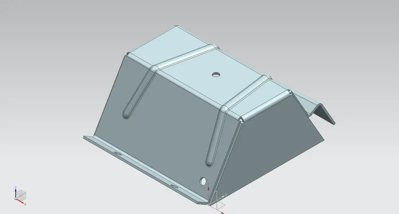
1.ISOMETRIC VIEW
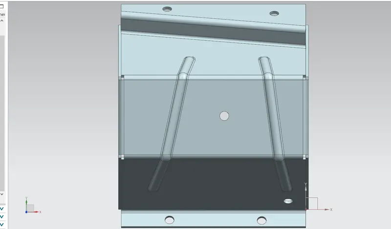
2.TOP VIEW
3.FRONT VIEW
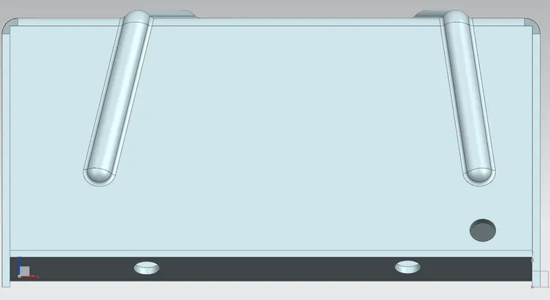
4.RIGHT VIEW
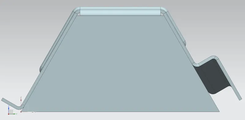
5.FLAT PATTERN VIEW
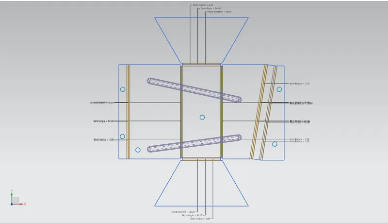
2D DRAWING
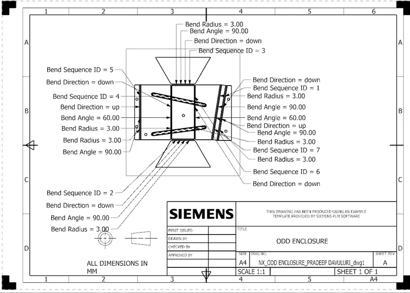
The 2D drafting of the odd enclosure is an shown in the below image, all the bend radius, bend ID, and bend bend angle is mentioned in the drawing very clearly,
CONCLUSSION
The odd shaped enclosure is designed successfully in the NX software and it helped me to know more about the sheet metal from solid command and i am used to it. the part and drawings of the enclosure is saved successfully.