Advanced Sheet Metal Design Using NX Cad Challenge_2_Box Assembly
BOX ASSEMBLY USING NX11
OBJECTIVE: the main objective or motive of the this challenge or project is to design or create a sheet metal box assembly using NX software or application and make us more familiar with the tools and
features available in the NX11 sheet metal domain.
INTRODUCTION
the Siemens NX is also known as Uni graphics NX is an advanced high eng CAD /CAM/ CAE software package originally developed by UGS corporation, but since 2007 it is owned by Siemens PLM software. it is used for tasks such as design, engineering analysis and manufacturing finished design by using included machining module.
NX11 introduces capabilities for convergnt modelling, rapid manufacturing, improved annotations, drafting and documentation and rendering. active workspace in NX11 is build around these items to provide seamless access to PLM capabilities right within NX.
NX sheet metal provides set of tools within the NX design environment that allows simple and fast design of sheet metal parts dependent on their material and manufacturing peocesses, the most common of which is straight brake metal forming.
the NX advanced sheet metal is now the product to choose for creating aerospace parts. typically the aerospace sheet metal parts have planar tabs and webs, with the flanges being offset from a curved surface of the fuselage skin for the frames and ribs in the wings have their flanges offset from the airfoil skin. using the advanced flange the tabs and webs are automaticaly trimmed andflanges added as a reference to the airframe or wing's skin.
the sheet metal box assembly is a body that is created by using features such as tab, flange and normal cutout, etc.., this type of assembly is used to store or to collect wastages. it looks like a dustbin used on the road side.
DESCRIPTION
the description of the desing of sheet metal box assembly is illustrated with the help of a flowchat given below, the flow chart is included with all the features and commands that are used in the design process,
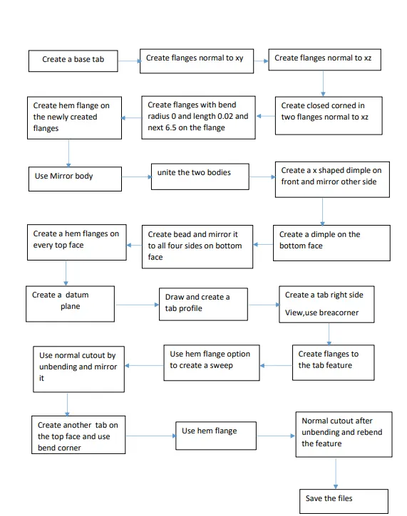
DESIGN METHODOLOGY
under the design methodology we will discuss about the various features that are used in the design of sheet metal box assembly,
SKETCH: NX sketch anticipates what you are going draw or design. it identifies geomentric relations for you with the surrounding geomentry. NX sketch works seamlessly with data reardless of the source. this feature is at the top left corner of the screen when you open the sheet metal domain in the NX software.
TAB: Tab is the most basic feature which is used to add some thickness to the sheet metal part. it acts like an extrude tool in the solid modelling. it creates a base feature by extruding a sketch along a
vector by thickness value or adds a material to a plane face.
FLANGE: in NX sheet metal flange command is used to add a flat flange at an angle to a planar face and adds a blend between the two.
CLOSED CORNER: the closed command feature is used to close the two adjacent flanges meet by extending the bends and flanges in the sheet metal applications.
HEM FLANGE: the hem flange modifies the model by folding the edge of a sheet metal flange over onto itself for the purpose of safe handling or to increase the edge stifness. it adds various curly shapes on the edges of the sheet metal model with the same thickness as the metal sheet. there are different types of hem flanges such as open type, closed type, open loop, closed loop, etc....... .
MIRROR BODY: the mirror body command is used to mirror an entire body across a datum plane. when you mirror a body, the feature is associated to the original body and we cannot edit or modify or change the mirrored body. this feature is used for symmetric objects.
UNITE: the unite command is used to combine the volue of two or more bodies into a single body or entity. the two bodies must overlap one another or must share faces so that the resulting body is a valid body.this command creates a unite feature.
DIMPLE: the dimple feature is used o lift an area of the model or drawing inside a sketch that simulates a stamping tool. the dimple command makes an indentation in the sheet metal part using aketch as its outline.
MIRROR FEATURE: the mirror feature command copies, and pastes the features on the model by mirroring through a plane or surface.
BEAD: the bead is like a raised rib in the sheet metal panel. it just requires only one sheet metal face which is active. it also simulates a stamping tool and this is performed to increase the stiffness of the sheet metal.
BREAK CORNER: the break corner feature is used to avoid sharp corners and make the corners round.change the radius to the required value in the dialogie box. in our application it is used as 10mm.
NORMAL CUTOUT: the normal cutout feature is used to cut the shpes normal to the plane. it cuts the model perpendicular to the sketch.in our application it is used cut rectangular holes.
UNBEND: the unbend feature is used to unbend the sheet metal body into a flat body. for this we have to specify a stationary face and select all the reaining faces by simoly draging a rectangle over the body. generally unbend option is used to create holes or any other shapes on the sheet metal body.
REBEND: rebend option is generally used whenever we use unbend option. it is used to bend back the sheet metal into it's original shape after performing intended operation such as making holes etc.., fot this we have to select the faces in a sequence similar to the sequence followed while unbending or we can simply drag a rectangle over the sheet metl t perform this operation.
DETAILED VIEWS
under the detailed views section we will see the different possible views of our sheet metal box assembly.
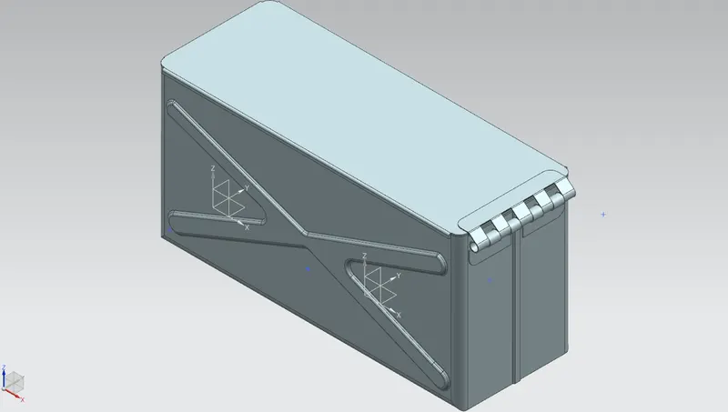
1.ISOMETRIC VIEW
the isometric view of the sheet metal box assembly is as shown in the below picture,
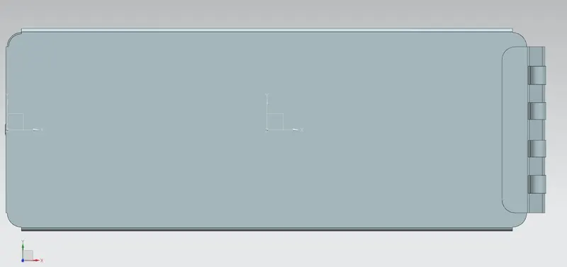
2.TOP VIEW
the top viw of the box assembly is as illustrated in the below figure,
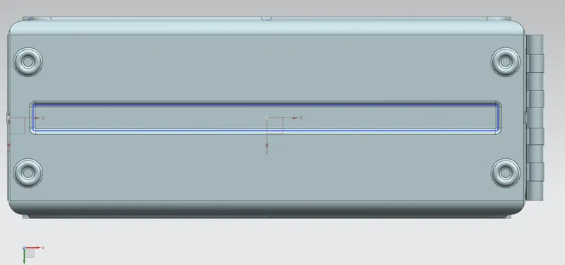
3.BOTTOM VIEW
the bottom view of the sheet metal box assembly is as shown below,
4.FRONT VIEW
the front view of the box assembly is as shown in the below figire,
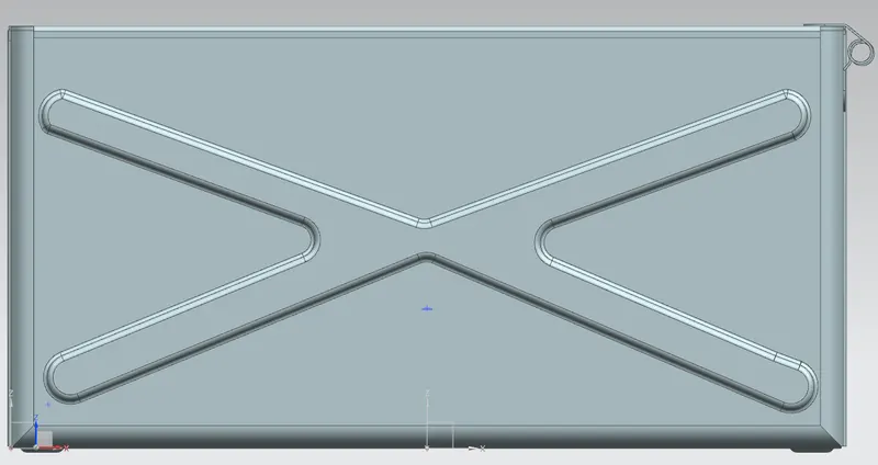
5.RIGHT SIDE VIEW
the right side view of the sheet metal box assembly is as shown in below picture,
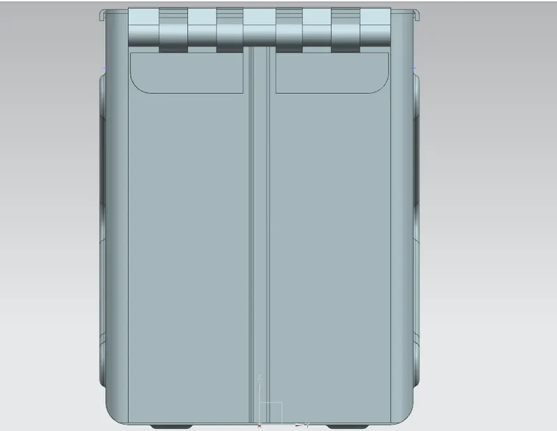
2D DRAFTING
the 2d views of the sheet metal box assembly is as shown in below figure,
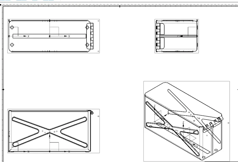
CONCLUSSION
the sheet metal box assembly using NX11 software is done and it helped me to get to know about features that are available in the NX sheet metal application and the results are satisfactory.