Advanced Sheet Metal Design Using NX Cad Challenge_6_Bracket
DESIGN OF BRACKET IN NX
OBJECTIVE: The main objective or motive of this project or challenge is to design a bracket usng Siemens NX software.
INTRODUCTION
The Siemens NX is also known as Unigraphics NX is an advanced high end CAD /CAM/ CAE software package originally developed by UGS corporation, but since 2007 it is owned by Siemens PLM software. it is used for tasks such as design, engineering analysis and manufacturing finished design by using included machining module.
NX11 introduces capabilities for convergnt modelling, rapid manufacturing, improved annotations, drafting and documentation and rendering. active workspace in NX11 is build around these items to provide seamless access to PLM capabilities right within NX.
NX sheet metal provides set of tools within the NX design environment that allows simple and fast design of sheet metal parts dependent on their material and manufacturing peocesses, the most common of which is straight brake metal forming.
The NX advanced sheet metal is now the product to choose for creating aerospace parts. typically the aerospace sheet metal parts have planar tabs and webs, with the flanges being offset from a curved surface of the fuselage skin for the frames and ribs in the wings have their flanges offset from the airfoil skin. using the advanced flange the tabs and webs are automaticaly trimmed andflanges added as a reference to the airframe or wing's skin.
The sheet metal brackets are used in applications to mount hold an object from antennas to tv's , projectors or street lights etc..,
DESIGN METHODOLOGY
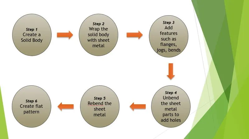
In this design methodology section we will discuss about how the sheet metal bracket is designed and which features or commands are used and the procedure followed. the below flow chart will give us the information about sequence of steps that are followed in the NX application in order to design the sheet metal bracket.
DESCRIPTION
The description part is mainly focussed on the various commands that we have used while designing the sheet metal backet.
SKETCH: NX sketch anticipates what you are going to draw or design. it identifies geomentric relations for you with the surrounding geomentry. NX sketch works seamlessly with data regardless of the sorce. the sketch command is arranged on the top left corner of the window when you open the NX application.
CONTOUR FLANGE: The contour flange command. Creates main base flange or second flange by extruding sketch in sheet metal application.
NORMAL CUTOUT : Normal Cutout command extract volumes from sheet metal by using sheet metal production principles. Cutting faces will be perpendicular to the sheet metal surface. it cuts the material by projecting a sketch onto the model and then cutting perpendicular to the faces intersected by the projection. You can use planar sketches or 3D curves to specify the section for the normal cutout.
BREAK CORNER: The break corner feature is used to avoid sharp corners and make the corners round. it rounds the corners to the required radius for the safe handling of the sheet metal.
UNBEND: The unbend feature is used to unbend the sheet metal body into a flat body. for this we have to specify a stationary face and select all the remaining faces. generally unbend option is used to create holes or any other shapes or features such as beads, dimples excetra on the sheet metal body.
BEAD : The bead is like a raised rib in the sheet metal panel. it just requires only one sheet metal face which is active. it is also simulates a stamping tool and this this is performed to increase the stiffness of the sheet metal.
REBEND : Rebend option is generally used whenever we use unbend option. it is used to bend back the sheet metal into it's original shape after performing the intended operations such as making holes r making beads or creating dimples.
HOLE: In the siemens nx modeling, hole command use to create a hole on one or more solid bodies in a part or assembly with option for counterbored, countersunk, and threaded. in our case we use this command to create general hole with a diameter of 20 mm.
VIEWS OF BRACKET
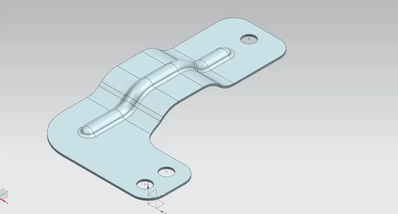
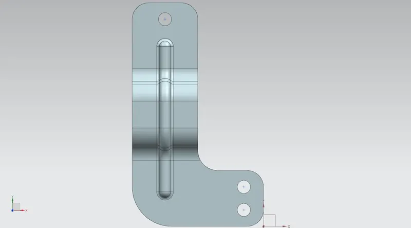
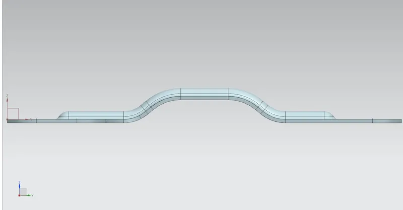
In this section we will see the possible views of the sheet metal bracket,
1.ISOMETRIC VIEW
2.TOP VIEW
3.FRONT VIEW
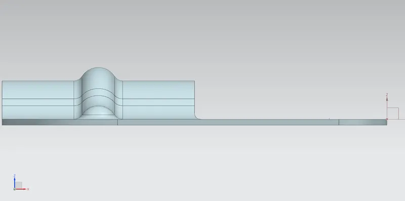
4.RIGHT VIEW
2D DRAFTING
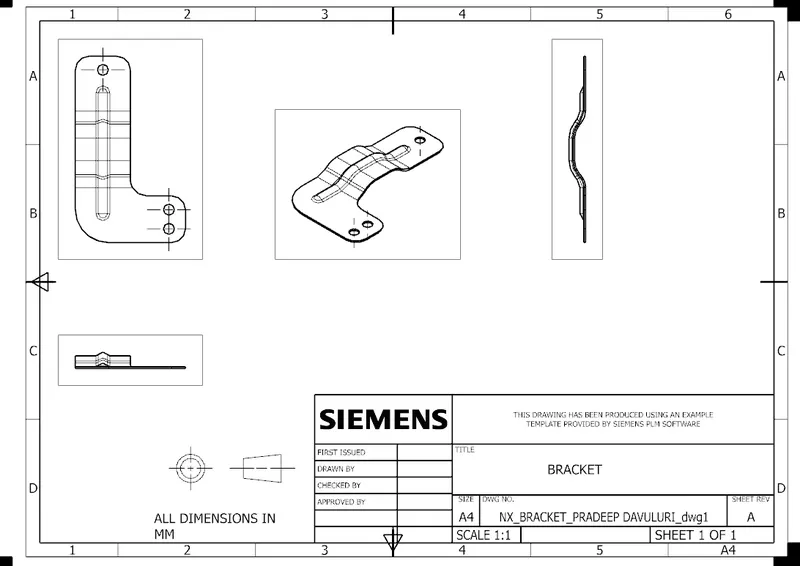
the drawing of the sheet metal bracket is as illustrated in the below figure.
CONCLUSSION
the design of sheet metal bracket using NX application is succesfully done and the file is saved safely and successfully.