Advanced Sheet Metal Design Using NX Cad Challenge_1_Casing Design
DESIGN OF SHEET METAL CASING
OBJECTIVE: the main objective or aim of this project or challenge is to create or design a sheetmetal casing using NX 11 application or software and to obtain 2d drawings from 3d design in different views and to learn the basics of the sheet metal domain in nx.
INTRODUCTION
NX sheet metal provides a set of tools within the Nx design that allows for simple and fast design of sheet matal parts, dependent on thier material and manufacturing process, the most common of which is straight brake sheet metal forming.
in NX modelling,complex uniform thickness parts are created either by using surfacing techniques and then thickening the result, or by starting with a solid shape ,blending and then shelling the part to get uniform thickness.
Nx delivers the next generation of design simulation and manufacturing solutions that enables companies to realize the value of the digitial twin. now here we are using 11th version of NX application.
casing is a device or part which is used to enclose or cover the machine parts in order to protect them. casings are found widely in all automotive desings and in all automobile vehicles.they are widely used in electrical industries.it is made accurately by using various features such as tab, flange, dimple, bends, bead etc..., in NX sheetmetal domain.
DESIGN METHODOLOGY
The design approach for this project or challenge is illustrated in the below folw chart .
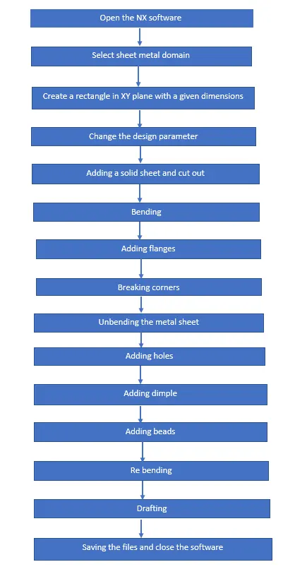
DESIGN DESCRIPTION
in this chapter we will descuss about the various features used in NX to complete this project.
SKETCH : in this feature we will draw the basic shapes of the profile which we are designing by selecting repective plane.this feature is on the top left side of the screen when you open the application.
TAB : this feature is used to add some thickness to our drawings. the default thickness is 3mm, but in our case change the thickness into 1 mm.
NORMAL CUTOUT : the normal cutout feature is used to cut the shape normal to the plane.we have to select the previously drawn drawing ehich we have to remove.in our case it is used to make a rectangular hole in the metal sheet.
BENDING : this feature is used to bend the sheet metal.select the line and manuplate the arrows in order to get required bend.define bend angle as 90 degrees for this operationand repeat the samething on the otherside too.
FLANGE : select the flange command, in the dialogue box select the edge to add the flange give the length as 5mm and angle as 90 degrees repeat the same procedure for the remaining three sides.
BREAK CORNER : the break corner feature is used to avoid sharp corners and make the corners round. in the dialogue box select the edge and make the method to blend and give radius as 1mm and then click ok.repeat the same procedure for remaining 9 corners.
UNBEND : this unbend option is used to unbend the sheetmetal to make it flat.in this select the stationary face and next select all other faces or simply drag a rectangle over all the faces. this is used to obtain a flat metal sheet.
HOLE : this hole feature s under the more button of the feature field tab.this is used to make holes of desired size and desired tyoe of hole, in the dialogue box use screw clearance hole as type of hole, with screw size of M2 and a H13 fit.select the depth as through body.
DIMPLE : dimple feature is used to lift an area of the model or drawing inside a sketch that simulates a stamping tool. the dimple command makes an indentation in the sheet metal part ,using a s sketch as its outline.
BEAD : the bead is like a raised rib in the sheet matal panel.it just requires only one sheetmetl face which is active.change the depth, radius and die radius in round bead edges to 1mm for our application.
MIRROR FEATURE : this feature is under the more button of the feature field.in our application this feature is used mirrot the bead in other three sides.
RE-BENDING : it is used to rebend the metal sheet into its original shape by selecting all the faces except the stationary face or it can be done simply by draging a rectanle over it.
FLAT PATTERN : flat patternoption is under the flat pattern feature , select the stationary face and click ok.
DRAFTING : basically drafting is a new domain which is used to create 2d drawings , create a new file, select sheet size as A4 and then go to base view feature, here in the dialogue box select option model view to FLAT PATTERN#1 and select suitable scale.the draft of the final casing is as shown in the below figure. 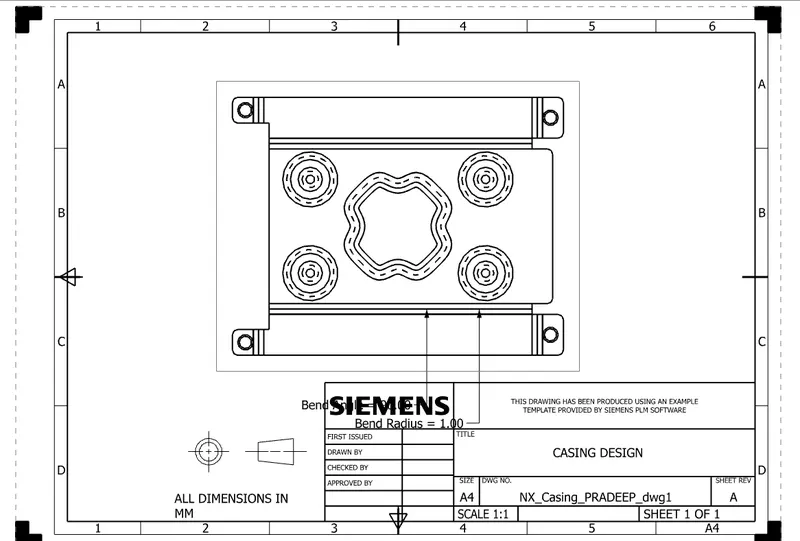
the other views of the casing in 2d are as the below picture
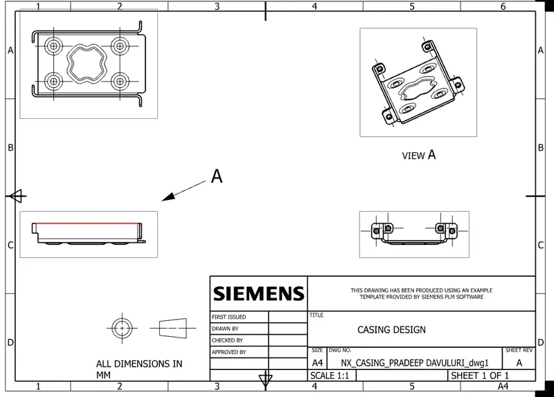
DIFFERENT VIEWS OF CASING
the isometric view of the the casing is as shown the below figure
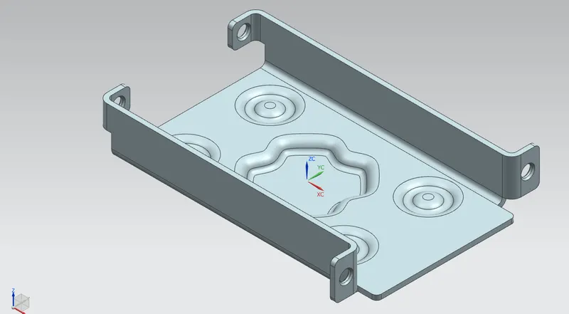
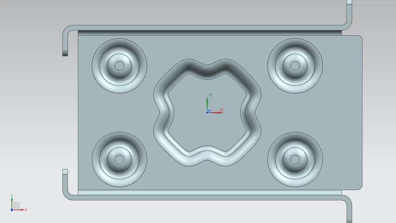
the top view of the casing is as illustrated in the below figure
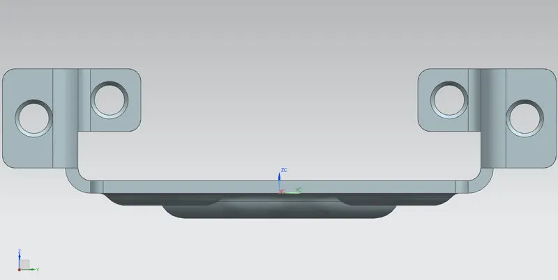
the right side view of the casing is as shown in the below figure
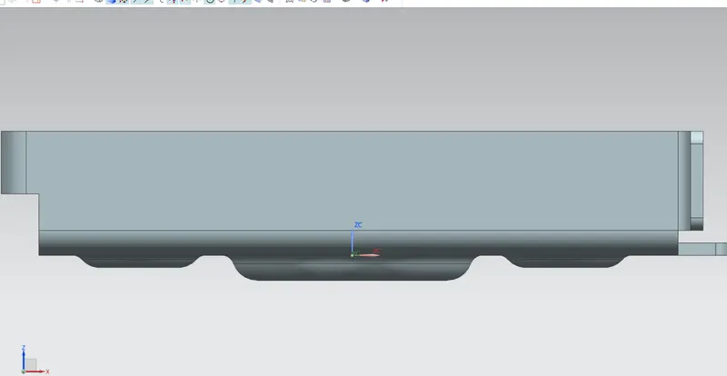
the front view of the casing is looks like the picture as given below
CONCLUSION
i am concluding that i have designed and drafted the sheetmetal casing by using NX11 software successfully and the results are accurate and satisfactory.