Week 9 - Attachment Feature Creation - Challenge 2
Objective: The main objective of this project is to create a screw boss and Dog house for coin holder
Screw boss
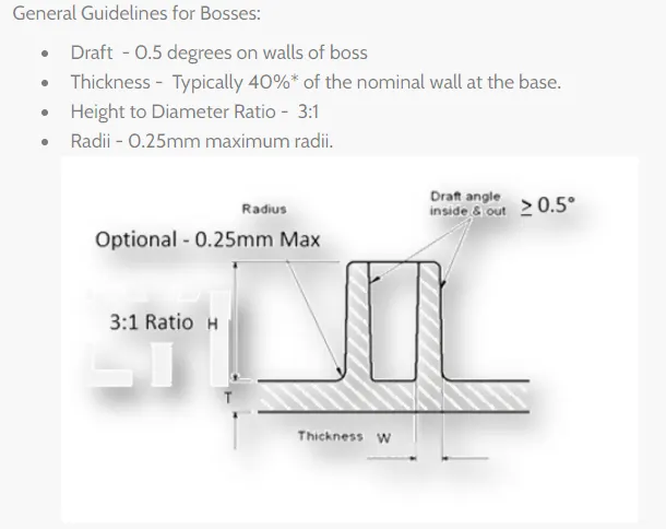
The boss is one of the basic design elements of plastic moulding, Bosses are usually cylindrical because that is the easiest form to the machine in the mould and it is also the strongest shape to have in the moulded part. The boss is used whenever we need a mounting point,a location point, a reinforcement around holes. The boss may receive an insert, a screw or a plain shaft either as a slider or a press fit.
In other words, the boss is not as simple as it looks. depending on its use, it may have to stand up to a whole combination of forces-tension, compression, torsion, flexing, shear and bursting so it must be designed accordingly.
We can start with a general design rule, using the principle we have already developed for ribs and walls. The boss can be thought of as a special case of a rib. one that is wrapped round in the form of a tube. An ideal boss, designed according to rib rules, would not produce a sink mark or stick in the mould but unfortunately, the tubular form of the boss would not be strong enough in most cases. In a real-life, most bosses break some rib design rib by necessity. This means that boss design is a compromise between sink mark and functionality. Rigidity is the simplest aspect of boss design. This can be achieved by supporting the boss design. This can be achieved by supporting the boss with buttress rib, and often by linking the boss to a side wall. The support ribs can be designed to normal rib rules so that sink marks and stress points are avoided.
DOG HOUSE
Dog House is an engineering feature used in the plastic trim design. Dog houses are used as supporting features. Sometimes other engineering features like snaps, locators. are mounted on them to increase their strength.
Dog houses are subjected to draft analysis to prevent breakage of the components during the ejection mould cavity. Dog house and other engineering components are built on the class B- Surface.
DRAFT ANALYSIS
Tooling must be cleared for easy ejection of the components, from the core cavity. In order to clear tooling certain value of draft is given to the components. A minimum of 2-3 degrees is provided on all plastic components.
Procedure to create screw Bosses
Step 1: Create a sketch on the extracted surface.
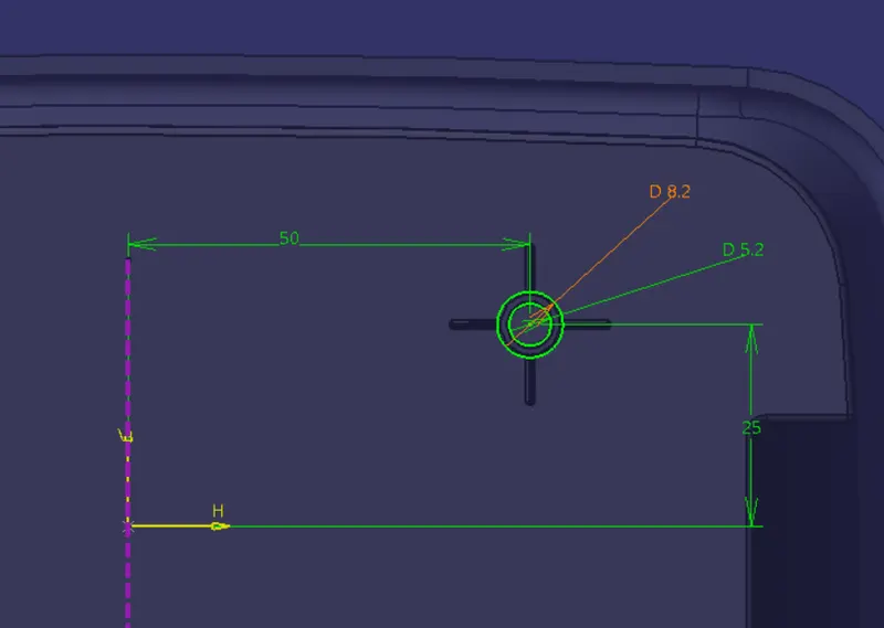
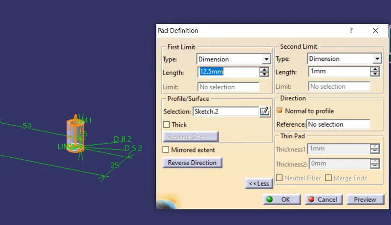
Step 2: Provide a Pad for the sketch.
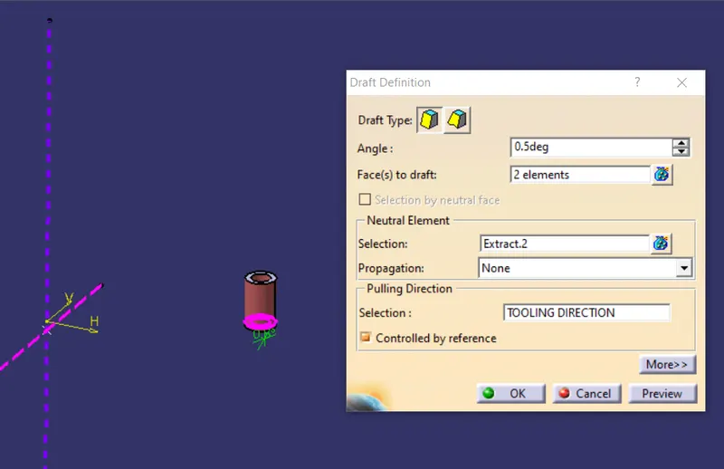
Step3: Provide a Draft for both inside and outside pad as per design guidelines 0.5deg by selecting a tooling axis as a direction.
Step 4: For support purposes provide a rib with four sides as per rib design guidelines.
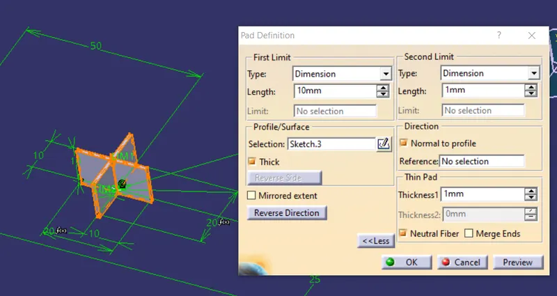
Step 5: By using a boolean operation use union trim for screw bosses.
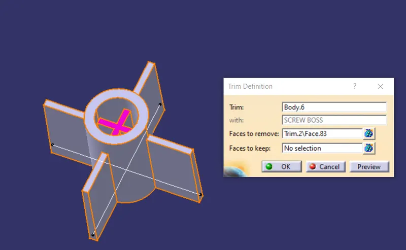
Finally assembly with the main part body.
DOG HOUSE
Dog House is an engineering feature used in the plastic trim design. Dog houses are used as supporting features. Sometimes other engineering features like snaps, locators. are mounted on them to increase their strength.
Dog houses are subjected to draft analysis to prevent breakage of the components during the ejection mould cavity. Dog house and other engineering components are built on the class B- Surface.
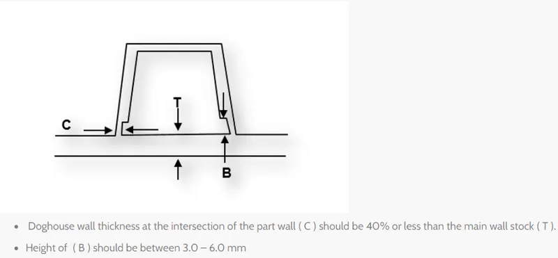
Procedure for Dog house
Step1: Create a sketch on the surface as a rectangle for a dog house we need only three sides faces.
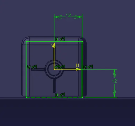
Step 2: Sweep or extruded options are used, but by using sweep here we can provide draft angle here itself.
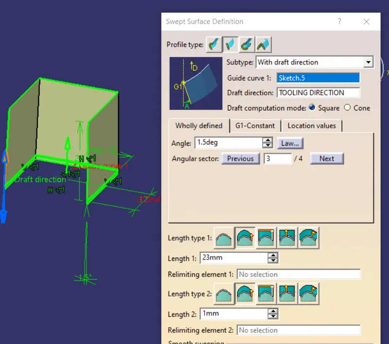
Step3: Close an upper portion by extracting a surface then offset them around 20mm
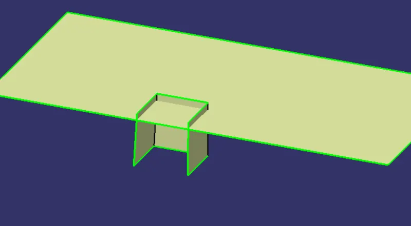
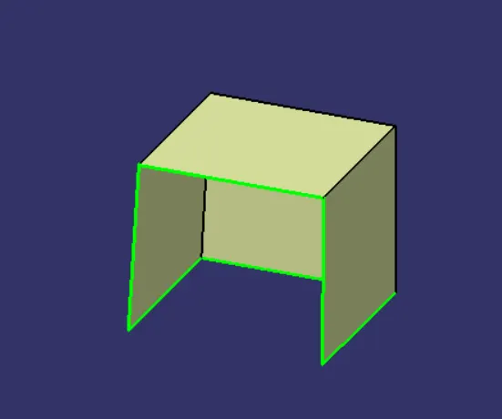
Step 4: Apply a thickness for the dog house around a 2mm
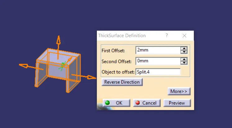
Step5: Provide a Draft angle around 1.5 deg, here for providing the draft angle we need to create a side core as a tooling axis.
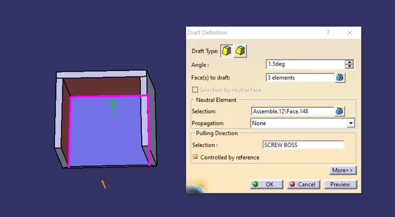
Step6: Provide a c Value up to the height 3 to 6mm.
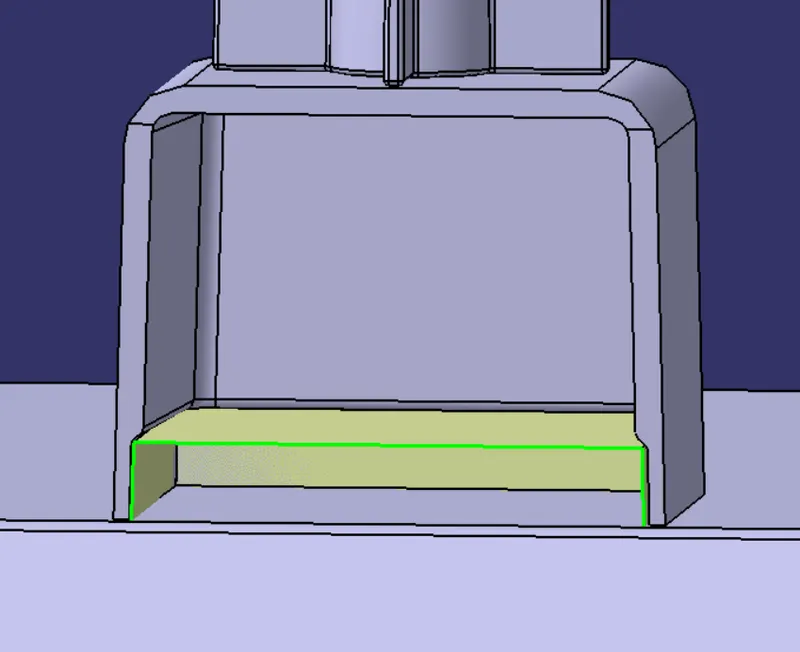
STEPS INVOLVED IN PERFORMING DRAFT ANALYSIS FOR SCREW BOSS AND DOG HOUSE
Draft analysis is performed to check whether the component is drafted completely. Draft is performed for easy ejection of plastic component during the process of injection moulding. Following are the sequence of
operation for draft analysis.
STEP1: Before performing draft analysis note should be made that the VIEW is set to MATERIAL MODE. Select the draft analysis from INSERT -> ANALYSIS -> FEATURE DRAFT ANALYSIS.
STEP2 : select feature draft analysis from analysis and select HIDE OR SHOW THE COLOUR SCALE and set the value of green to 0.45 deg and red to 0deg. 0.48deg represents the maximum draft angle, for SCREW BOSS.
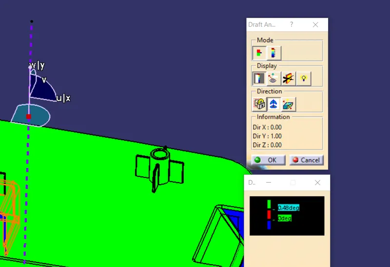
STEP2 : select feature draft analysis from analysis and select HIDE OR SHOW THE COLOUR SCALE and set the value of green to 1.45 deg and red to 0deg. 0.48deg represents the maximum draft angle, for DOG HOUSE
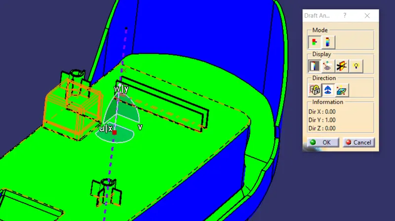
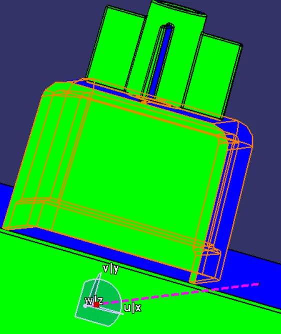
STEP 3: Drag the compass and set it on the „Tooling Direction‟. Use the compass to select new draft direction and reorient the compass direction then select the solid on which feature draft analysis is to be performed. If the orientation of the compass is inverted select the inverse direction command in the draft analysis. The green colour in the figure below represents that the component has cleared draft analysis in the „Tooling Direction‟ direction. .
Views
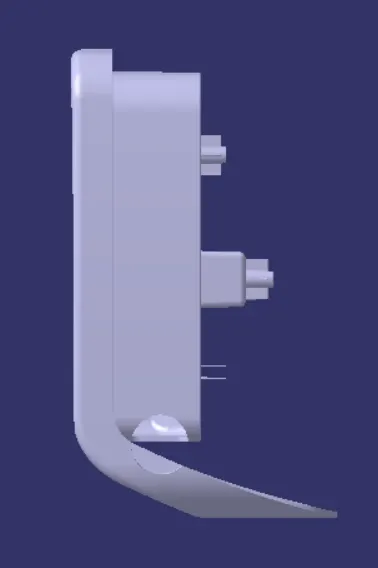
Front view
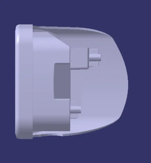
Right view
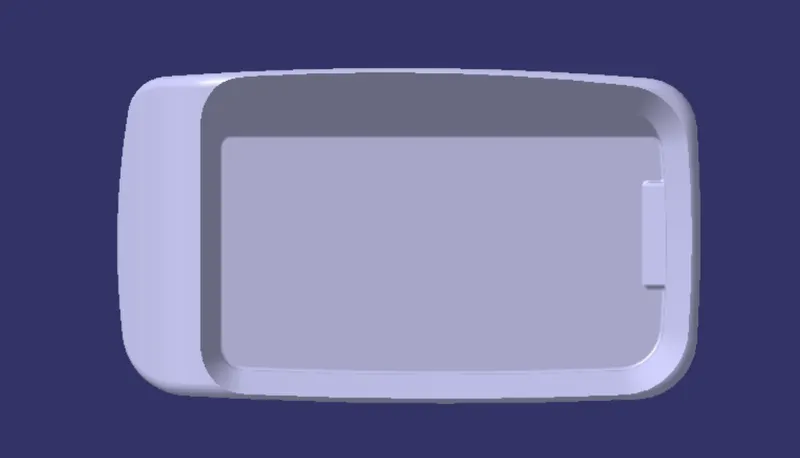
Top view
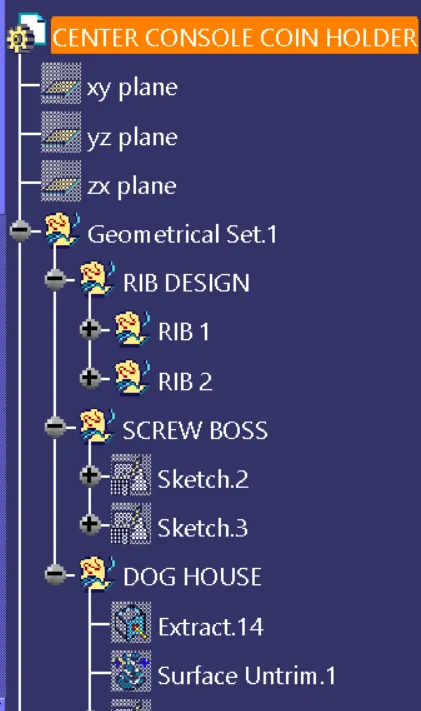
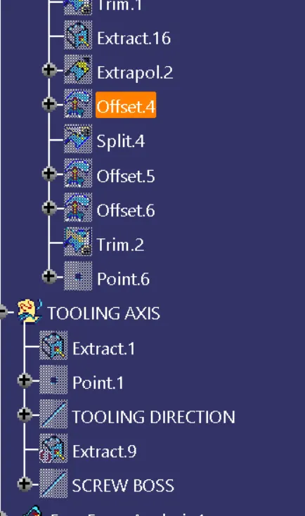
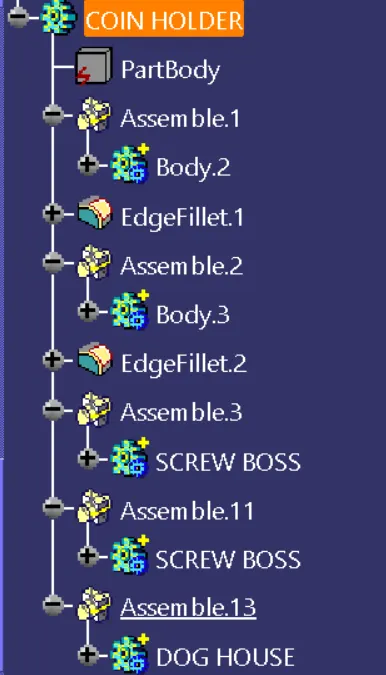
Feature tree
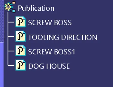
Publications
Conclusion
Engineering features as Rib , screw boss and Dog house are created for coin holder as per there design guidelines and OEM stands.