Advanced Sheet Metal Design Using NX Cad Challenge_2_Box Assembly
Title: To Design sheet metal for Box Assembly
Objective: To design the sheet metal for box assembly using NX CAD, by using different types of feature is used to model box assembly as per Industrial aspect.
Introduction: The NX Softwar intergrates with multidisciplinary principles, conceputal design, 3D Modeling, Documentation, engineering analysis,graphical simulations and concurrent engineering. NX CAD is widely used as Computer Aided Design Software in various fields like Aerospace, Automobile, Manufacturing industries.
Methodology:
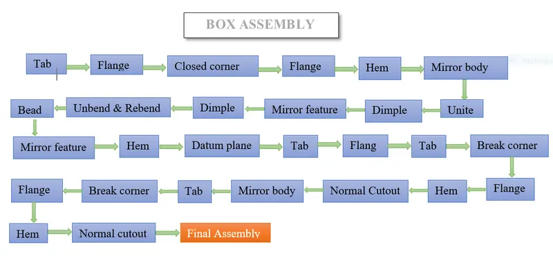
Features used to create Box Assembly
Tab: This command is a Base feature by extruding a sketch along a vector, and its is a first feature used in sheet metal,and also adding the material thickness.
Flanges: Flanges command is used to add a flat flanges at an angle to a planer face and add bend between the two . a flanges consists of two resgions manily Bend and Web region by selecting edges can reverse the flanges as required by appling length and angle to bend. Flanges has many types as Contour, Lofted,Hem, Jog flanges.
Closed corner: This command is used to close or gap between the model in sheet metal.
Hem flange: It is used to modifiy the surface by folding edges of sheet metal and used to remove sharp untreated edges & make it safe for handling.
Mirror body: This feature is used to mirror the body by selecting required plane to mirror.
Bend button: This feature is used to bend the sheet metal tab features by selecting bend line to bend and adding the angle ,Reverse side or direction.
Unite: Unite command is also known as combine, this is used to combine the required feature/body in single body.
Datum plane : It is used to select the required plane as per designer choies to create sketch.
Break corner: This command is used to break the corner in sheet metal part in sharp edges to convert to bend or smooth edges to avoid the sharpnes at the end, applying the radius to break corner.
Unbend Feature: Unbend feature is used to get flat sheet metal part selecting the stationary face and slecting bend face to get flat part.
Rebend feature: In previous unbend feature is used to create flate sheetmetal part to get Rebend selecting the faces to obatin required shape.
Dimple Feature: Dimple in sheet metal part provide more strength and rigity to flate structure of the components, in this design selecting curve and adding the depth valve, depth reference rounding paoperties like punch , corner radius valve ,validation parameter like minimum tool clearance valve to get Dimple feature.
Normal Cutout: Normal cutout feature is used to cut the material as required depth valve by selecting curve.
Different view of Box Assembly in NX CAD
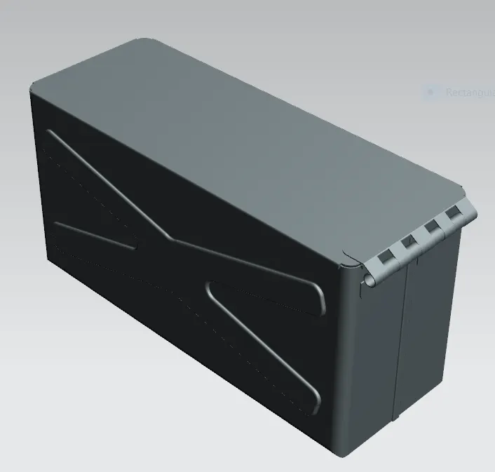
Isometric view
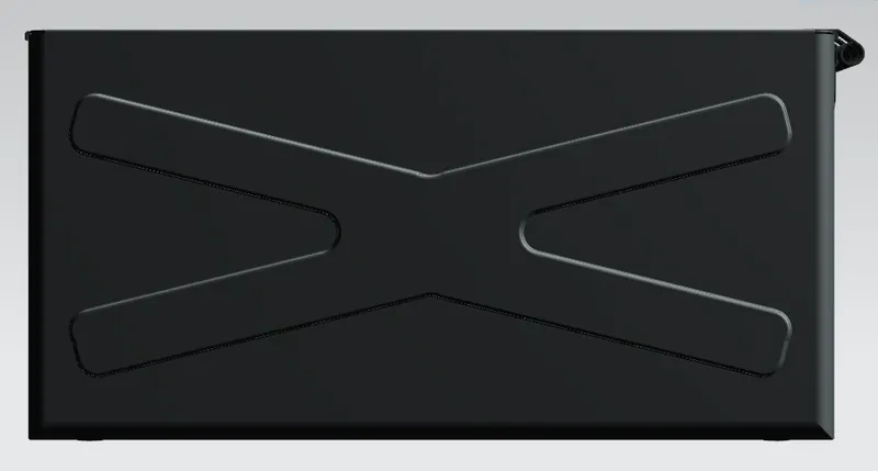
Front view
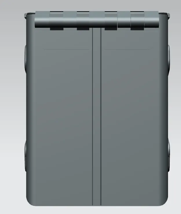
Right view
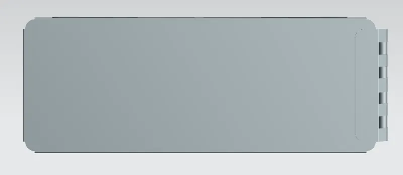
Top view
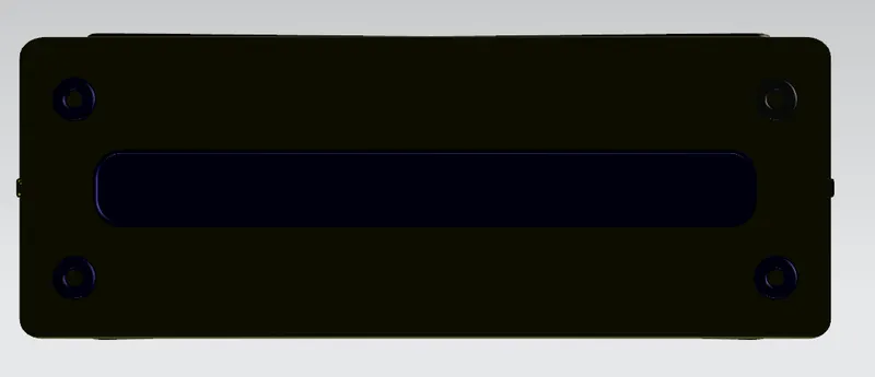
Bottom view
Drafting of Box Assembly
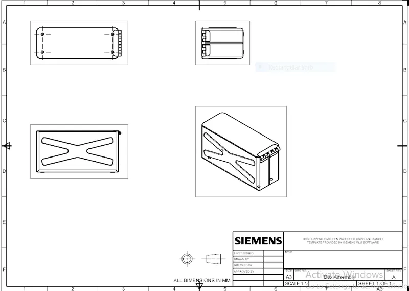
Conclusion: This project is completed by NX CAD software by designing sheet metal for Box Assembly by using various features are used to create Box Assembly.