Advanced Sheet Metal Design Using NX Cad Challenge_1_Casing Design
Title: SHEET METAL FOR CASING DESIGN USING NX CAD SOFTWARE
Objective: To learn sheet metal design process parameter and designing the casing design using NX CAD and familiar with usages of tools while designing casin.
Introduction: In this project we designing the casing design by using NX CAD and also using the some basic features used to design casing like Tab, Flanges, Bend, Breaking corner, unbend and many more feature are usend in NX CAD. It is widely used in many industries like Automobile, Aerospace, many more. CAD is a Computer Aided Design is a technology concerned with using computer system to asist in the creation, modefication,analysis,and optimization of a design.
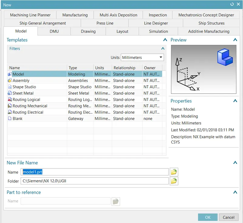
In the begining New templates shows NX CAD software shows manily units , file name ,floder
Methodology:
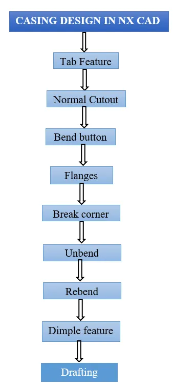
Feature used for Casing Desing:
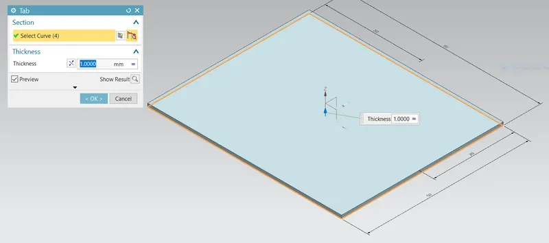
Tab: This command is a Base feature by extruding a sketch along a vector, and its is a first feature used in sheet metal,and also adding the material thickness.
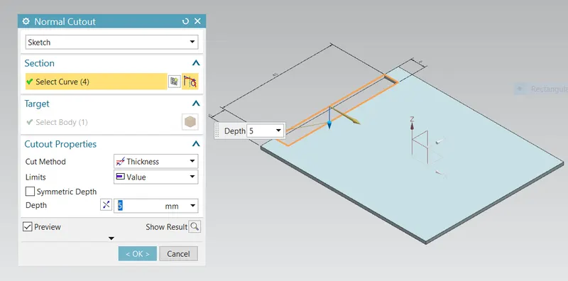
Normal Cutout: Normal cutout feature is used to cut the material as required depth valve by selecting curve.
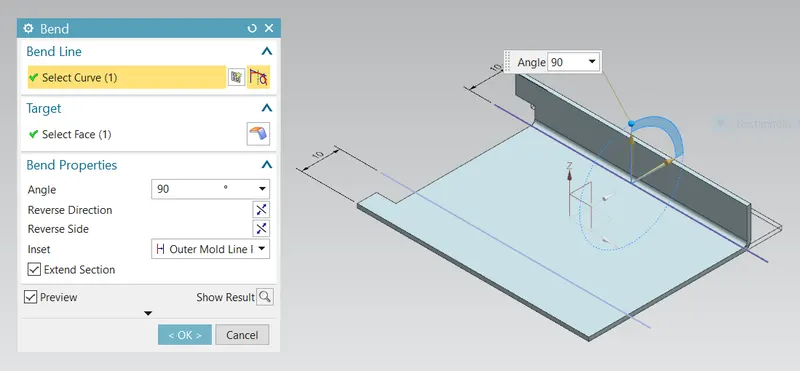
Bend button: This feature is used to bend the sheet metal tab features by selecting bend line to bend and adding the angle ,Reverse side or direction.
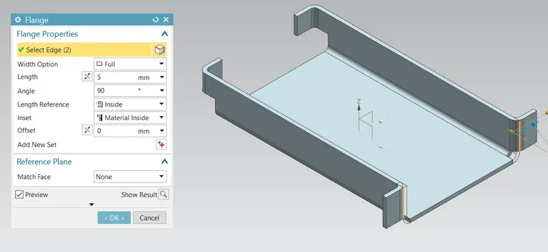
Flanges: Flanges command is used to add a flat flanges at an angle to a planer face and add bend between the two . a flanges consists of two resgions manily Bend and Web region by selecting edges can reverse the flanges as required by appling length and angle to bend. Flanges has many types as Contour, Lofted,Hem, Jog flanges.
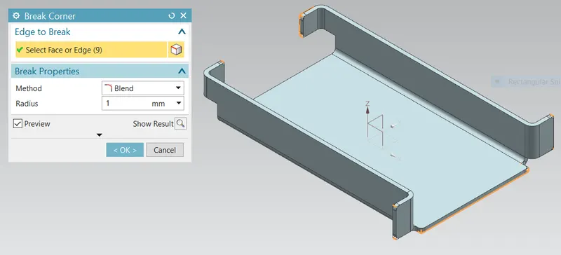
Break corner: This command is used to break the corner in sheet metal part in sharp edges to convert to bend or smooth edges to avoid the sharpnes at the end, applying the radius to break corner.
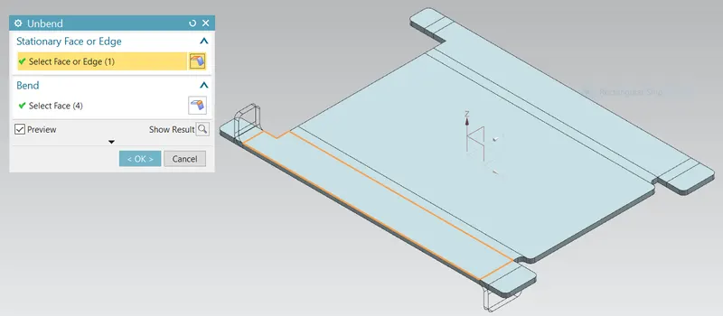
Unbend Feature: Unbend feature is used to get flat sheet metal part selecting the stationary face and slecting bend face to get flat part.
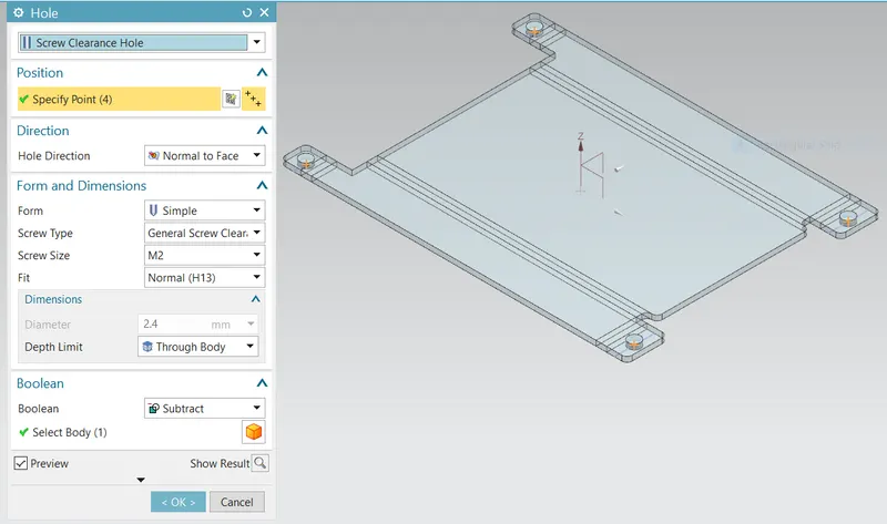
Hole feature: Hole features in sheet metal part can create either simple,counterbore,countersink,tappes hole. In this design first four point is sketched symmetric to X-axisin position and apply the hole feature.
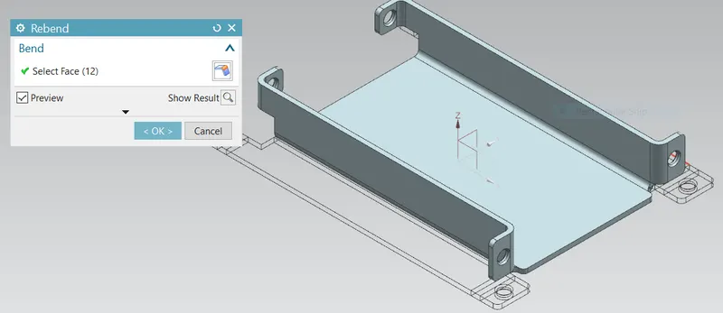
Rebend feature: In previous unbend feature is used to create flate sheetmetal part to get Rebend selecting the faces to obatin required shape.
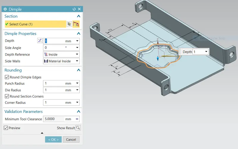
Dimple Feature: Dimple in sheet metal part provide more strength and rigity to flate structure of the components, in this design selecting curve and adding the depth valve, depth reference rounding paoperties like punch , corner radius valve ,validation parameter like minimum tool clearance valve to get Dimple feature.
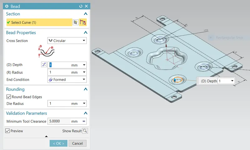
Bend feature: Bend feature is used to lift the materials along the counter of a sketch that simulate stamping tool by selecting cross section as circular,U-shaped,V-shaped.
Procedure to Design Casing in NX CAD
- Open the new templete select units as required for NX ending file formate is .prt extenstion.
- In application select the sheetmetal ,then Menu button preference Sheetmetal add material thickness,bend radius,Relisf depth,Relief width,Neutal factor valves to obtain to design the sheet metal components.
- Select a plane as per requirement to sketch to draw rectangular add dimension as per requirement.
- Tab feature is used in sheet metal this ia a first or base feature for sheet metal applying material thickness.
- Create a new sketch on P plane draw rectangular sketch and its is parallel to XY Plane.
- Normal cutout feature is used to cut the material as pre requirement.
- Create a new sketch on Top plane ,draw two symmetric horizontal line.
- Add Bend button feature ,select one line as bend line use angle 90 degree and apply the same procedure for other symmetric line.
- Apply Flange feature length is 5mm,width option is full,length preference inside.
- Add Break corner feature at the sharp edges ,blend radius is 1mm.
- Unbend feature is used inside the P Plane for sheetmeatl component in Flate surface.
- Create a new sketch on P plane draw line aslo add point on line .
- Apply Hole feature ,select center point on the line as per requirement .
- Again Rebend feature is used to sheet metal component to regain to its orgional position.
- Create a line and studia spline sketch on XY Plane ,select a 16 point to draw studia spline.
- Dimple feature is applies for move curve button.
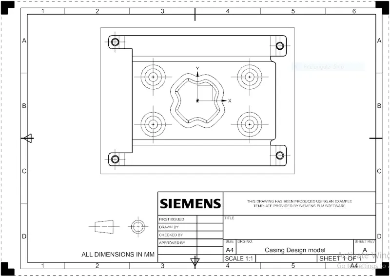
- Finally Drafting for casing design sheetmetal components in Drafting sheet.
Different Views for casing design
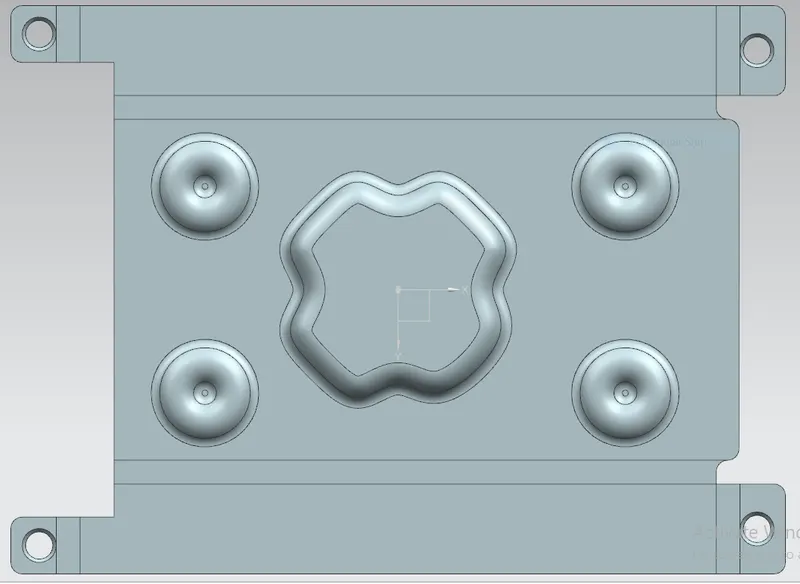
Bottom view
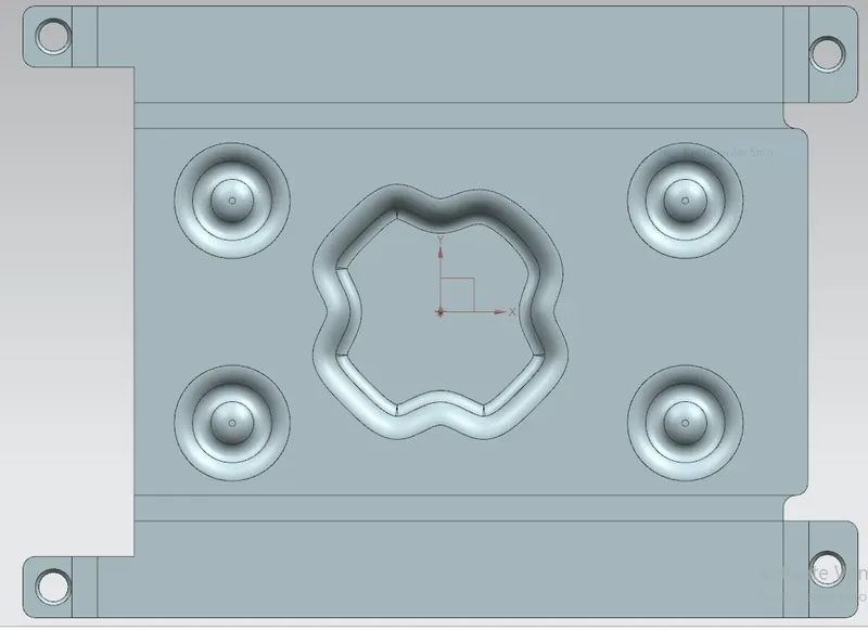
Top view
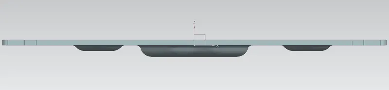
Front view
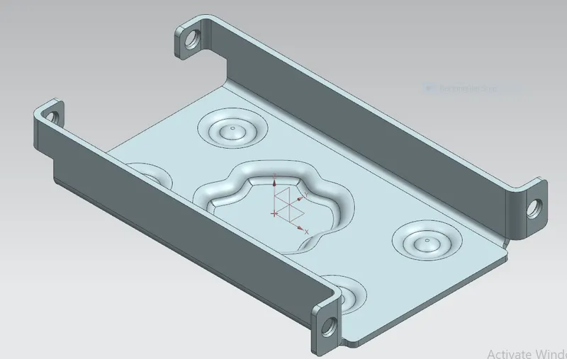
Isometric view
Drafing for casing design
After completeing the design ,the execution or the manufacturing of the component requires a technical drawing of the components with provide scale and with accuracy.
Conclusion :
In this project sheet metal casing design is done by using NX CAD and also gained a deep knowledge on features used to create Casing design like Tab,Flanges,Normal cutout,bend,dimple feature.