Advanced Sheet Metal Design Using NX Cad Challenge_6_Bracket
Title: Creating a Bracket for sheet metal using NX CAD
Objecive: By using 2D Drawing creating 3D model in NX CAD as per required Dimension, to create Bracket using Sheet metal features as per Industrial aspects
Introduction: Sheet metal parts can be found from the small light fixtures to the automotive body parts because of their high strength despite having low weight and its resistance to corssion, based on requirement and standared sheet metal of varying thickness are used.
Methodology
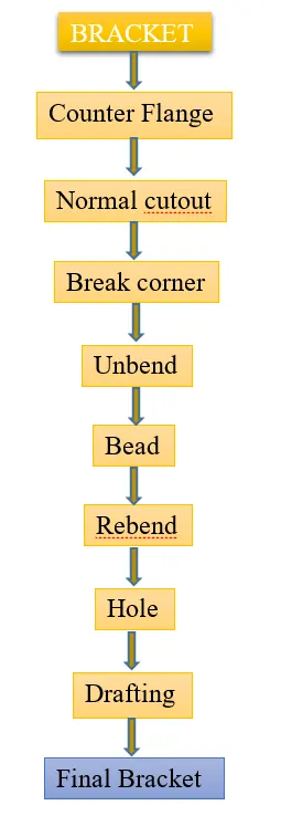
Bracket discription
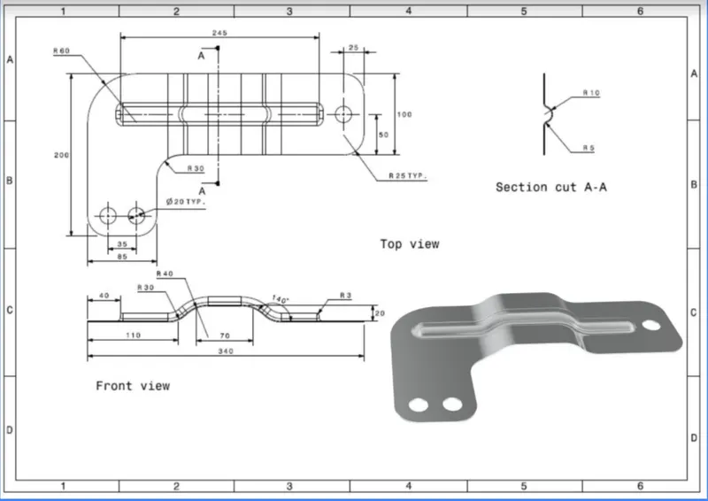
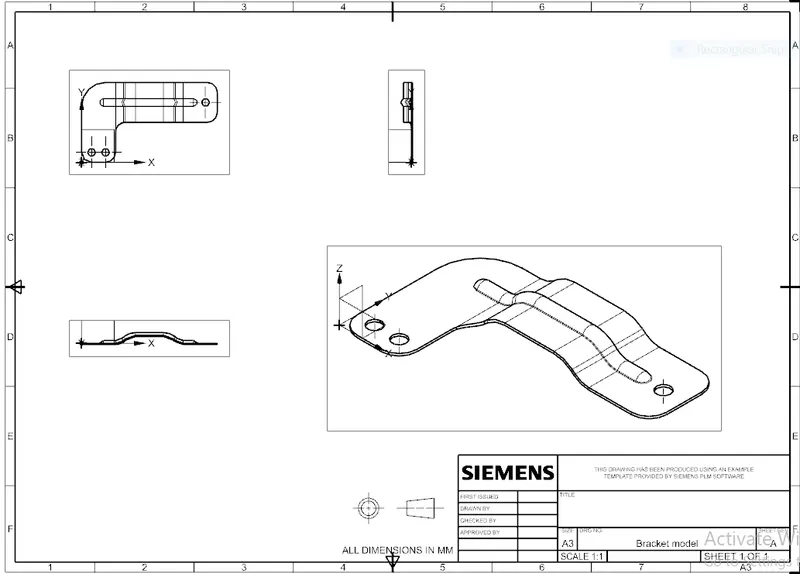
2D Drawing: As 2D drawing refers to designer for design the model using some software as per required dimension to create model.
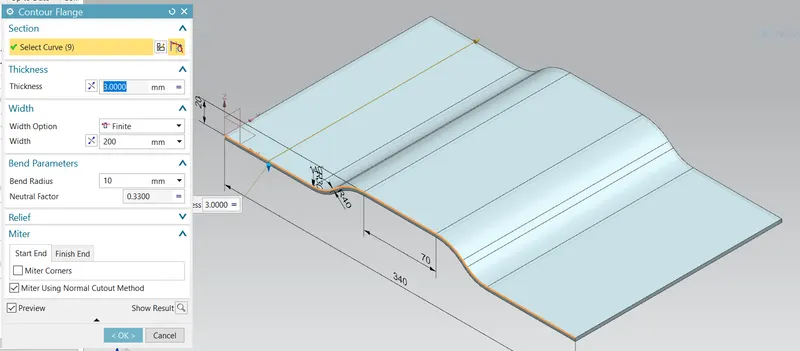
Counter flange: This command is used to Create base feature by extruding a sketch along a vector or add material by sweeping a sketch along an edges.
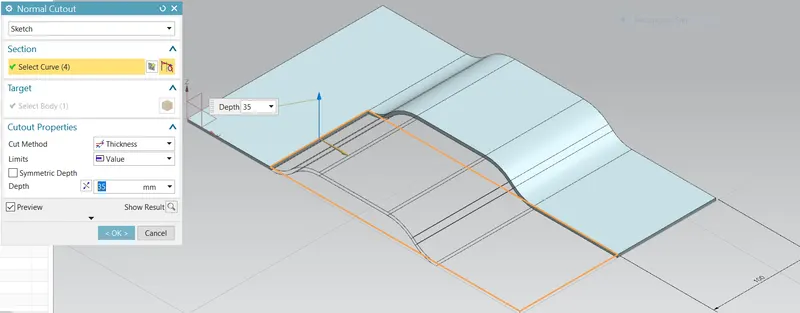
Normal cutout: This command is apply to cut the material as depth value to cut the material as per required dimension.
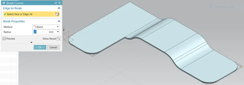
Break corner: Break corner feature is used to break the edges as smooth corner to the edges.
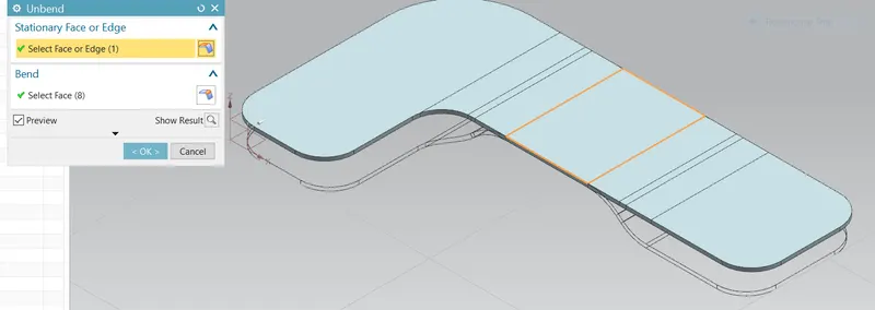
Unbend Feature: Unbend feature is used to get flat sheet metal part selecting the stationary face and slecting bend face to get flat part.
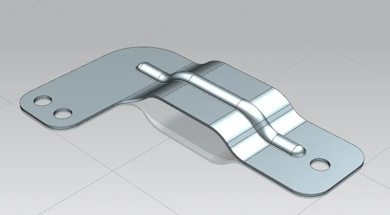
Rebend feature: In previous unbend feature is used to create flate sheetmetal part to get Rebend selecting the faces to obatin required shape.
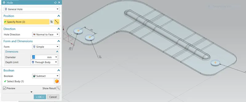
Hole feature: Hole features in sheet metal part can create either simple,counterbore,countersink,tappes hole. In this design first four point is sketched symmetric to X-axisin position and apply the hole feature.
Drafting
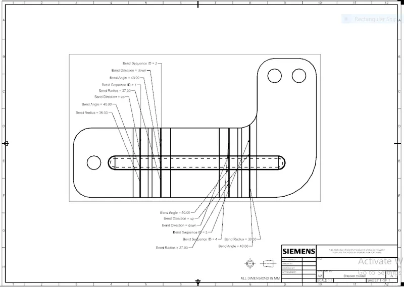
Flat pattern: This command is manily for 2D design also indicate the bend angle.
Conclusion : As per 2D drawing dimension sheet , completed Bracket in sheet metal by using NX CAD as per required Dimension.