PROJECT :- Attachment Feature Creation
AIM:- COIN HOLDER WITH ALL ENGINEERING FEATURE
EXPLANATION:-
CLASS A SURFACE CREATION
- Class A Surface of coin holder is imported first.
- Extract base surface and create new axis system by creating a point on the surface.
- Now check the class A surface by using boundary, now untrim the boundary into 2 element which will be used in future.
TOOLING AXIS CREATION:-
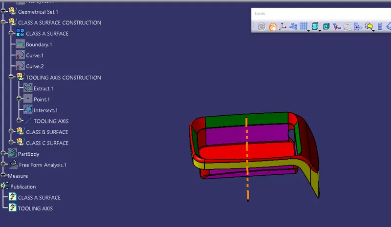
- For this component we bisect with the plane and component.
- By seeing bisect we observe that one wall is at 90degree.
- For creating tooling axis for this component just create a normal line using the point we created intially.
CREATION OF CLASS B SURFACE:-
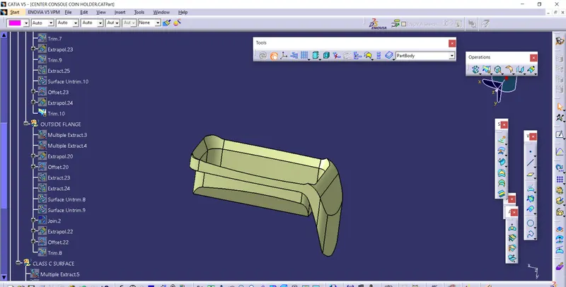
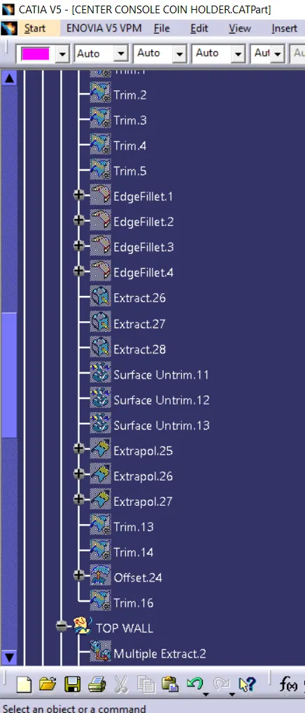
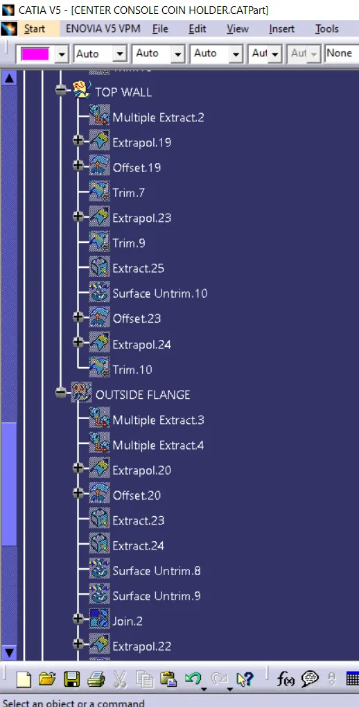
- Note in the feature tree, Class B surface has been divided by into 3part.They are Side wall,Top wall and Outer flange.
- Extract the surface of class A and untrim them.
- Now extrapolate them and offset them by 2.5mm as it is the thickness of the component.
- Trim them to the desired result.
- Similary process is followed for the other two but for outer flange we offset it inward instead of outward.
CREATION OF CLASS C SURFACE:-
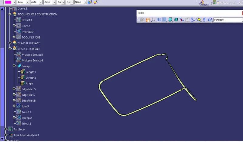
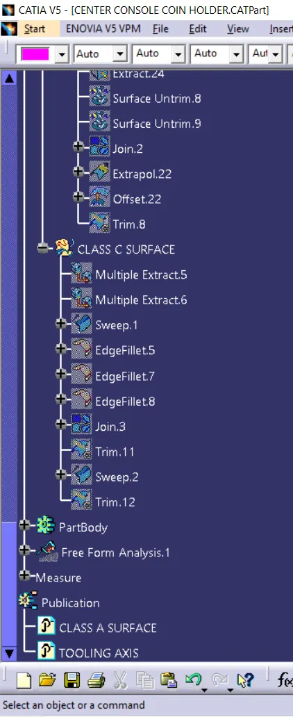
- For class C surface we extract the boundary and surface of outer flange of class A surface.
- Now we create surface sweep to create class c surface using subtype: with referance surface.
- we give 4mm or more thickness to class C surface.
- Now we add fillets to the sharp edges.
- Join class C surface with class A.
- Now trim with class B surface.
SOME SMALL CHANGES:-
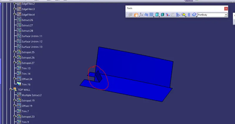
Creation of this small surface had been left so we will create this surface first.
- Extract from class A surface and untrim them.
- Extrapolate them and trim them .
- Now offset them.
- Now replace trim16 with trim1 and we get the final result.
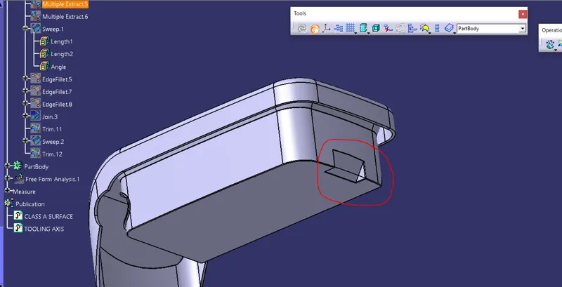
Now open part body and Thicken it to get solid body.
DRAFT ANALYSIS:-
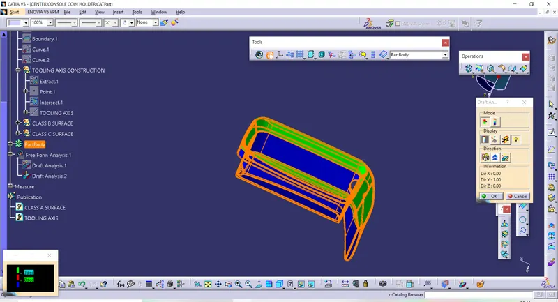
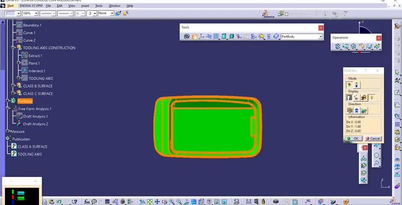
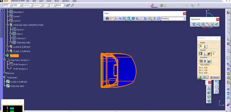
RIBS CREATION:-
- We insert a new geometrical set for ribs creation.
- Extracting the surface where we want to create rib will be good idea but we can also proceed without extracting the surface.In this case we have extracted the base surface which is extract 29.
- Now using that extract we create a positioned sketch and taking tip of tooling axis as projection point.
- We draw a line in the sketch and extrude it to height of 12.5mm which is (5*t) according to designing rule.
- Thicknen them upto 1mm according designing rule (w=0.4t).This is the wall thickness of rib.
- Now we provide draft to each side of the rib which is 0.5deg using tooling axis a direction.
- Now we add the rib to the main body using boolean operation.
- Now we add fillets to the ribs of 0.25mm value.
- This is our final result we want.
- Now cross check that all measurement provided is according to designing rule or not to avoid plastic defect which is called sink marks.
- We create an intersection of the body with xy plane and measure all the required area.
- For measureing rib root we do things differently.
- Create a tri-tangent circle and diameter of circle should be equal or less then (t+0.25t)mm. In this case dia is 2.68mm which is good.
- Similary,We can create other ribs just maintain at least (2t)mm distance between them.
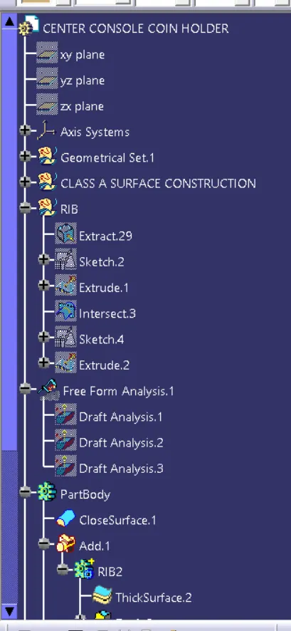
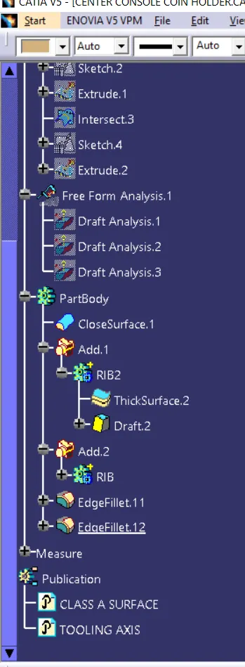
FEATURE TREE:-
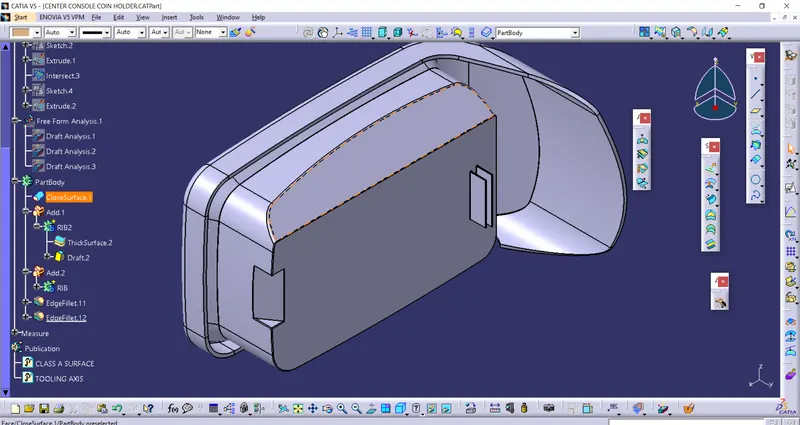
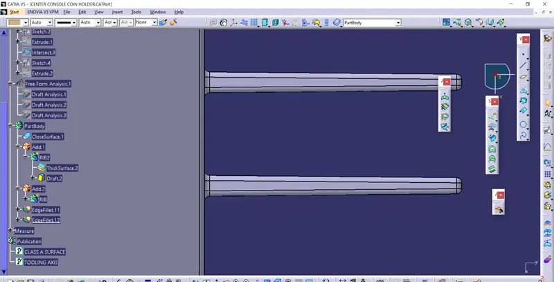
ORIENTATION OF RIBS:-
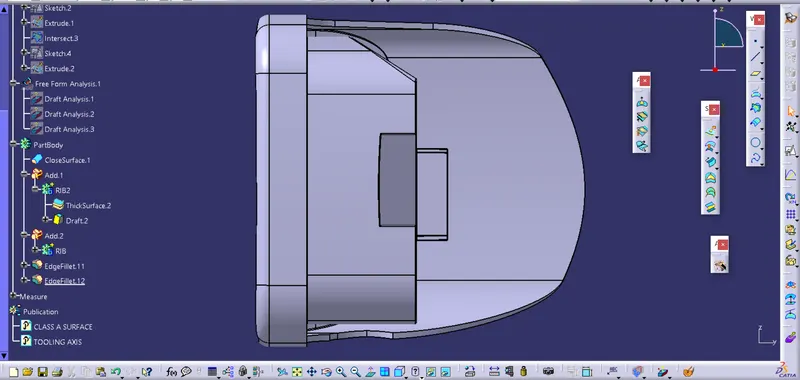
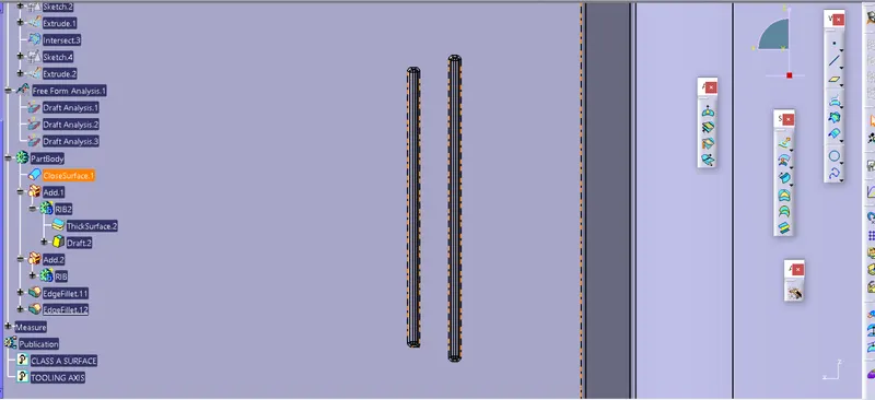
SCREW BOSS CREATION:-
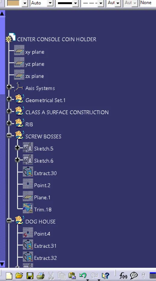
- As we know that for any feature creation a sketch is needed. So, first we draw two circles on the surface of coin holder.
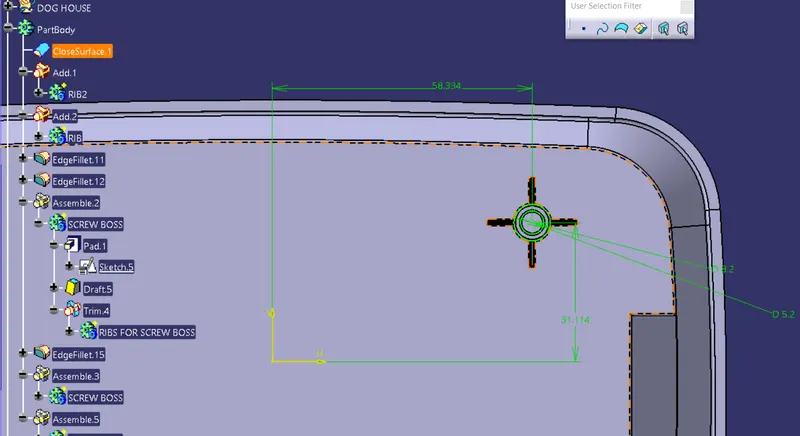
- Now we pad it to height of 12mm which is from height to diameter ratio i.e 3:1.
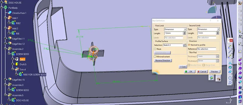
- Now draft of 0.5deg is provided to the outer face of boss using tooling axis a pulling direction and base a neutral element.
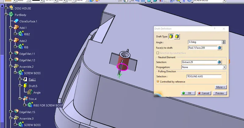
- To support screw bosses we create ribs.
- Copy that sketch and make two line like cross and make all other element construction except cross.
- Now pad it to certian height but it sholud be less then height of screw boss.
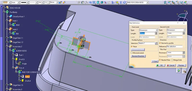
- These ribs also follows all design rule of ribs which is created above.
- Now union trim rib with screw boss to remove inner face and will also make them one body.
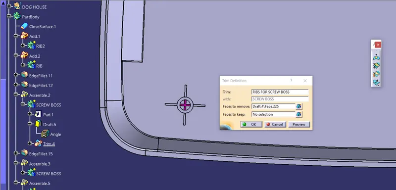
- Now add edge fillet of 0.25mm to all edgeds.
- Assemble screw boss to main body.
- To create another screw boss we copy and paste special with link and we get new screw boss.
- Now we can translate where we want using translate.
CREATION OF DOG HOUSE:-
- Extract the surface of coin holder to create dog house sketch.
- Sketch is being created for the dog house.We make rectangle and open one of it face.
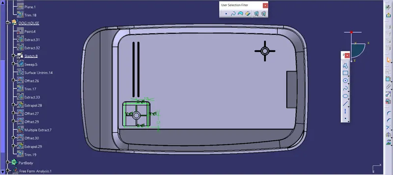
- Now we sweep the sketch with 1.5deg draft along tooling axis to height of 21mm.
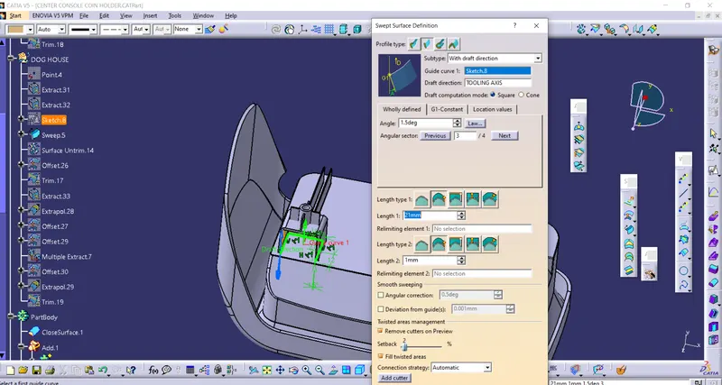
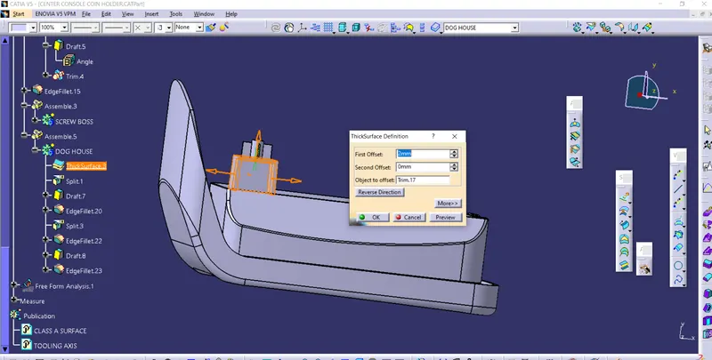
- Insert new body and thicken the sweep to 2mm.
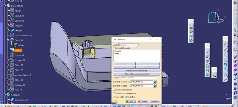
- Now we untrim the extruded surface and offset it to height of 22mm to close the top face of dog house.
- Now perform trim to get required surface.
- We extrude one of the face of dog house and extrapolate it and offset it to 22mm to remove the extra part in front portion of dog house.
- Perform split to get desired result.
- create other tooling axis to clear the side core.And giving a draft of 0.5deg to the inner face to get clear easliy.
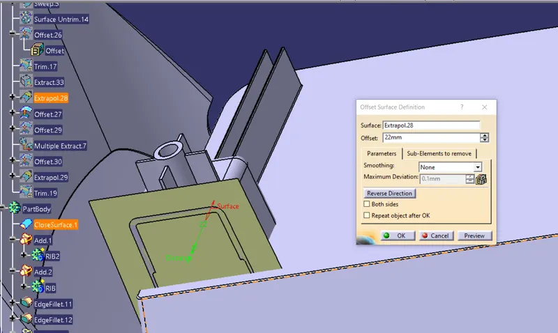
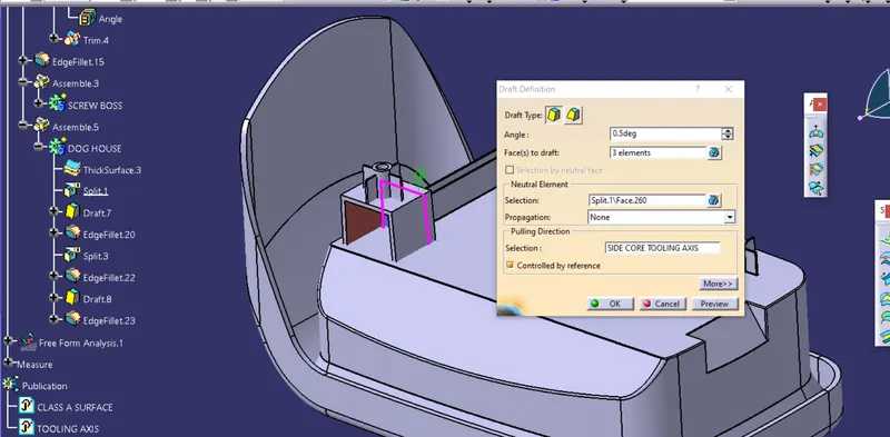
- Now to get lower cut of dog house we offset the untrim surface to 4mm.
- Extract the inner face of dog house and offset it inward to 1mm.
- Trim the both surfaces.
- Assemble it to main body.
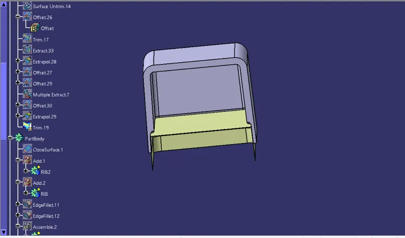
- Split the trim surface with body to the lower cut
- Draft is also provided to top face of lower cut.
- provide edge fillet of 0.25mm to cut face.
- and edge fillet of 1mm to inner face and 3mm edge fillet to outer face.
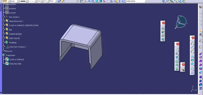
- Now we translate screw boss to the top of dog house which is our final result.
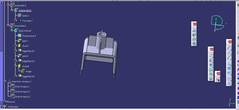
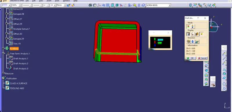
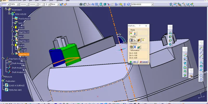
DRAFT ANALYSIS OF DOG HOUSE:-
FOR INNER FACE
FOR OUTER FACE:-
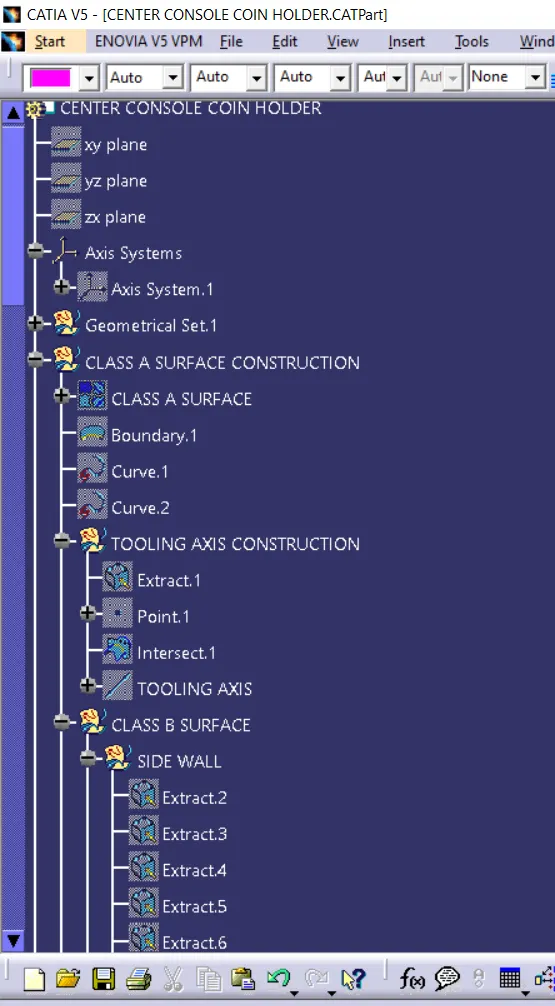
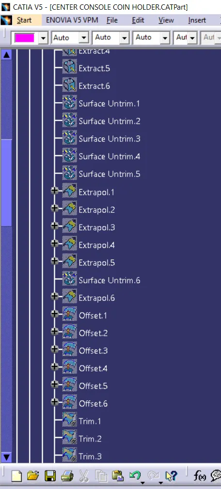
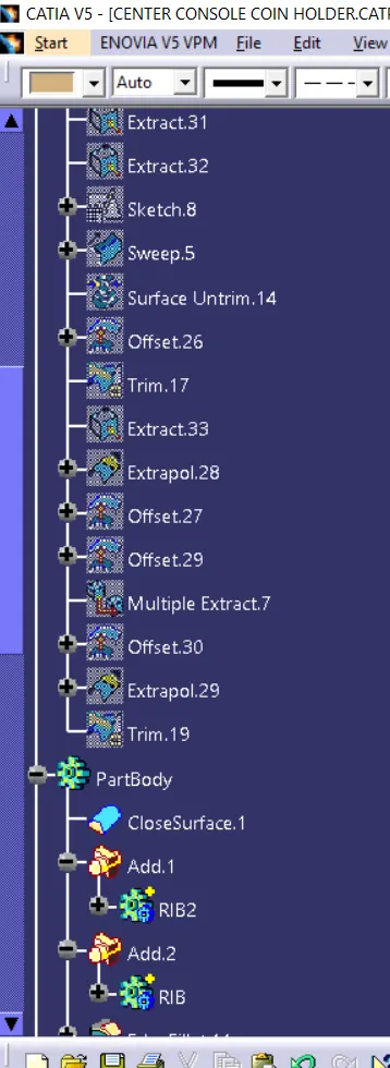
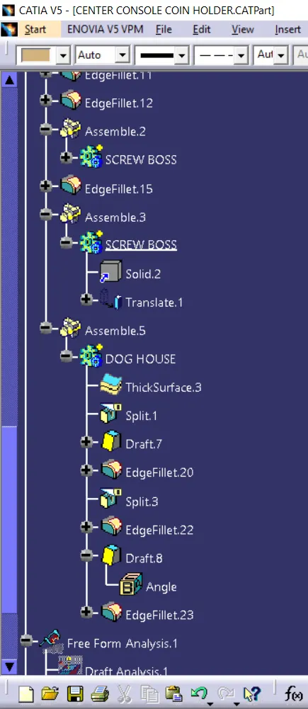
FEATURE TREE
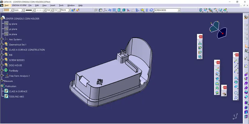
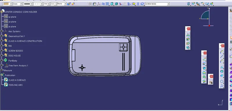
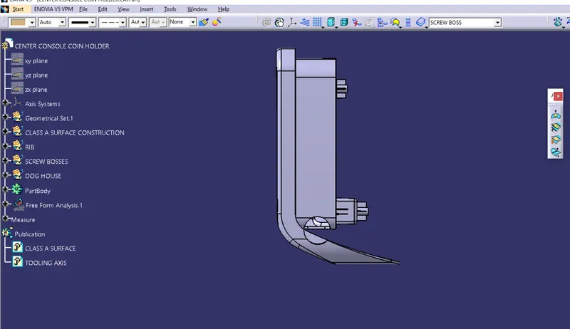
DIFFERENT ORIENTATION FOR FINAL COMPONENT WITH FEATURE
THANKYOU