Week 9 - Attachment Feature Creation - Challenge 2
Q:- A detailed report should be done explaining the draft analysis and the tooling axis creation.
Aim:- To create tooling axis and perform draft analysis.
Introduction:-
- Tooling axis:- It is axis about which component is being manufacturer. Core moves along with this axis. It gives the direction of ejection of component.
- Draft analysis:- It ensures sufficient inclination to be provided to surfaces of part. Sufficient draft ensures easy removal of part from core and cavity. This has to be carried out before part is send to CAE.
Procedure:-
a. Tooling axis creation:- Following are the steps involved in tooling axis creation
- Check for continuity of given class-A
- Visual check for tooling axis and create dummy tooling axis
- By observing it is conclude that tooling axis must be created perpendicular to class-A
- so flat surface of extension region is chosen
- Taking middle point on that surface
- A line is drawn from that point perpendicular to surface
- And this line will be our main tooling axis
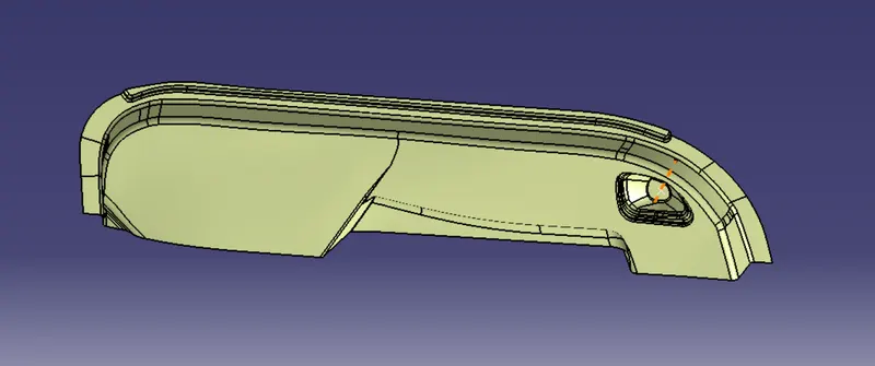
b. Side core axis:- As this part includes dog house. So it needs to have side coring axis for dog house moulding. This axis perform same function as that of main tooling axis. But side core moves along this axis and not main core. Following steps has to be follow in creating side coring axis:-
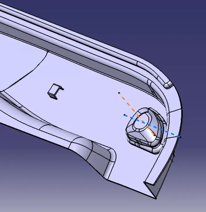
- This axis must clear dog house while manufacturing
- A line is drawn from same point which is used in main tooling axis
- Line drawn from that point in X component direction
- This line will be side coring axis
- In above picture blue line will be side coring axis
c. Draft analysis:- Following steps has to be follow for draft analysis
- First of all we need to activate material from customize view parameter section
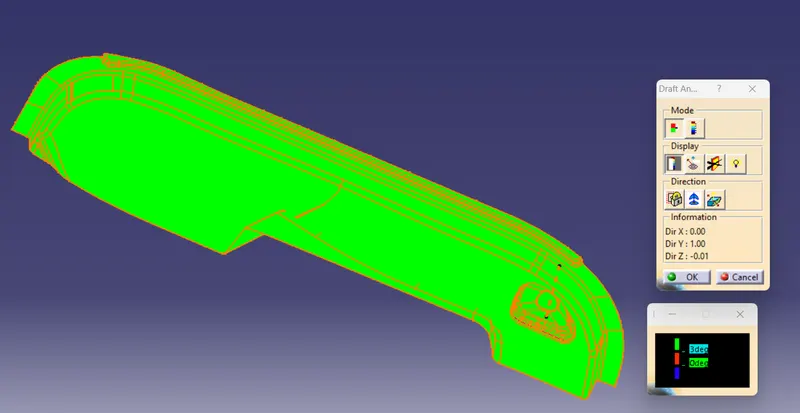
- Using draft analysis tool, we need to alined co-ordinate system with tooling axis and lock it
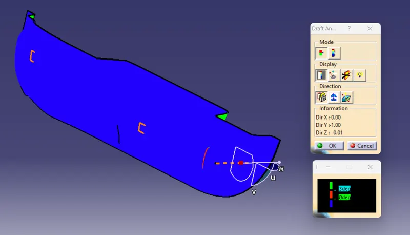
- Then by clicking on surface of part we can see colour shading
- Green colour tells us passing of surfaces in draft analysis, that is they have minimum draft angle needed
- Red colour shows rejected surfaces
- While blue colour shows passing of minimum draft angle but in reverse tooling axis
- Provided class-A gives green colour in direction of tooling axis, so it passes the draft analysis
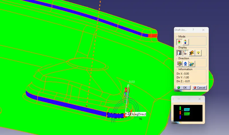
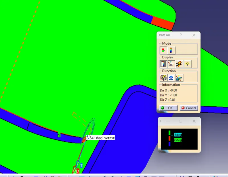
- But some areas of class_A are rejected in draft areas, as draft is not provided for for some areas
- Draft in such areas is around 0.4 degree as shown in below picture
- So it need to inform class-A desgner and ask to repair those regions
- As well created solid body also passes draft analysis, hence it has minimum 3 degree of draft on each side
- But as same like class-A, some areas rejected, this will be due to bad class-A.
Class-A:-
Rejected region:-
Solid_body:-
front

rear
Rejected areas:-
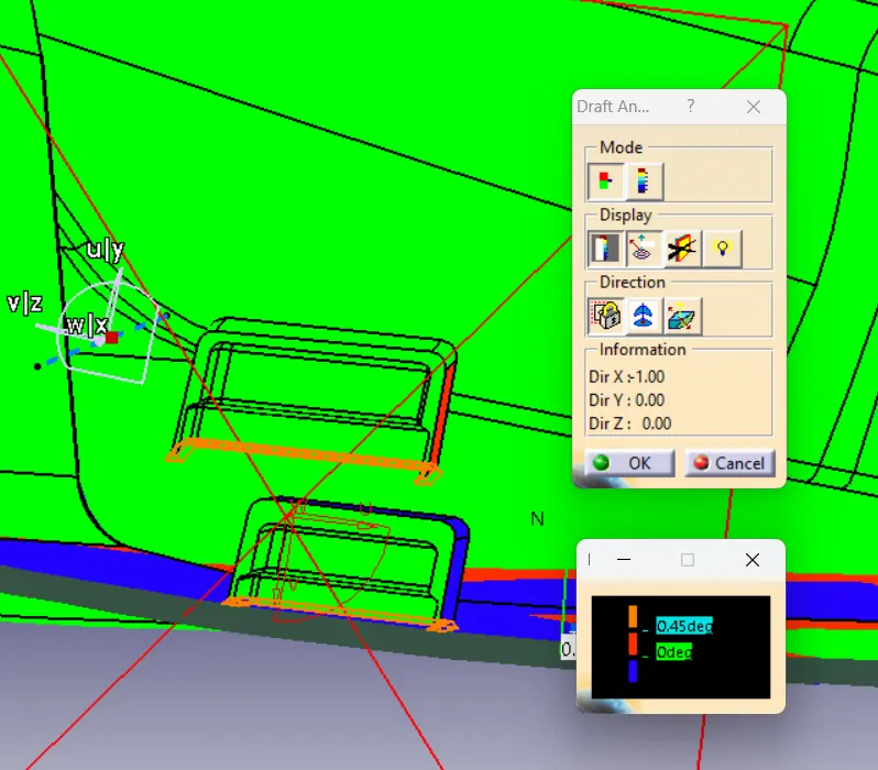
Draft analysis also carried out for dog house, with 0.5 degree of minimum draft. Dog house passes the draft analysis by clearing minimum 0.5 degree of draft.
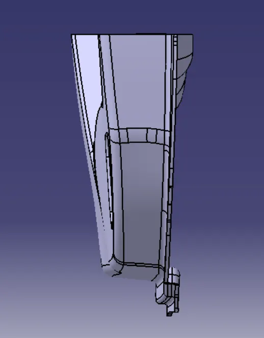
- Screenshots of the completed design in various orientations (Isometric, Front, Side, and Top View)
Side
Back
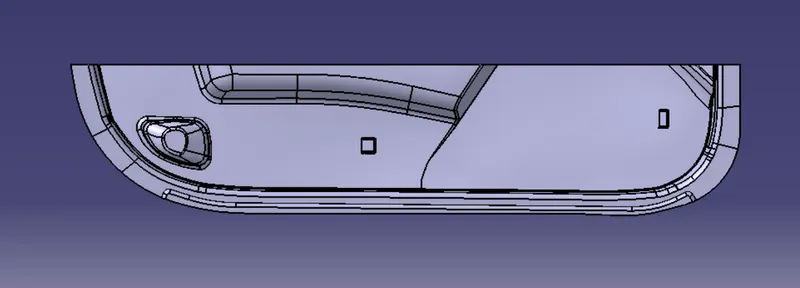
Front
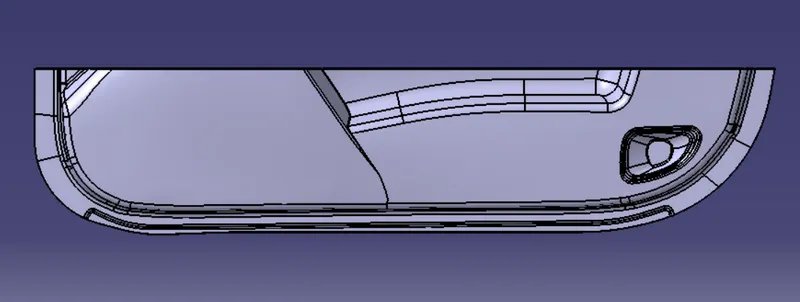
Top
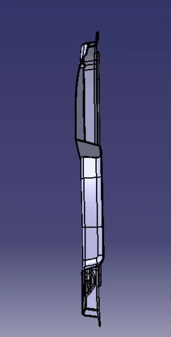
Iso
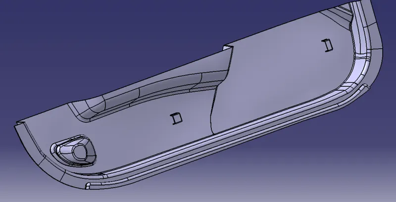
Conclusion:- In this way door trim with side core axis is done. Performing draft analysis with defining tooling axis and side core axis is also carried out.