Week 3:- BiW Fixture Design Methodologies Challenges
1. What is Design Methodology?
ANS:- following are the steps involved in design methodology
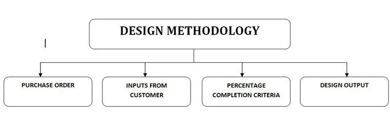
1. Purchase order :- PO is the documentation we get from the customer. the requirement of customer with the price is mentioned on PO. without PO we must not start our design procedure.
2. Input from customer:- It includes various requirements Of customer. Customer provides standards, constraints, considerations, etc to be maintained
3. Percentage completion criteria:- This includes scheduled completion of project. It includes detailed schedule like what percentage of project has to be completed in a certain time.
4. Design output in this stage we provide 2D, 3D and CAD data to the customer. We also provide BOM and GD and T
2. What are the inputs required from the customer to start designing a Fixture?
ANS:- Following at the requirements we needed from customer to start the design of fixture:-
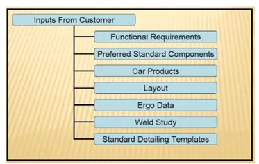
1. Functional requirement:- In this section customer has to provided functional requirement of the fixture. It may be Hemming fixture, Welding fixture, storage fixture or checking picture
2. Preferred standard components:- Customer provides list of standard components they want to use in their fixture. like standard risers, shims, blade, mylars,etc.
3. Car products:- It includes part list, clamp plan, CAD files of car part product for which fixture is to be design, assembly process sheet GD and T.
4. Layout:- It includes layout of Assembly line. We get information of distance between different stations, location of robotic stations, Flow of panels, loading and unloading details, etc.
5. Ergo Data:- For the operator to stand , accessibility of every part while maintenance ergonomical design is necessary.
6. Weld study:- Weld study includes details about weld points, type of welding needed and gun details.
7. Standard detailing templates:- As every company have different standards of detailing sheets, so customer need to provide their standards of sheets
3. What is the input we get from "Car Products"?
ANS:- Car products is the list of design for which we have to develop fixture it includes products as follows
1. GD and T:- In these customer provides geometrical dimensions and tolerances required for their fixture. It is necessary information as proper holding of components is our priority. So details of GD and T while designing pins, clamps is necessary.
2. CAD files for car parts:- The 2D 3D files of parts parts for which fixture is to be develop is necessary.
3. Part list:- The list of parts included in assembly need to be mentioned. By this information we can understand our assembly of product and can plan fixture design. Due to this information we can plan our weld gun positions and another assembly fixtures.
4. Clamp plan:- It gives information of clamping of panel. We must not change the clamping position. Changing of clamping position may lead to damage of panel or other accidents.
5. Product Assembly process sheet:- It includes assembly information of product. We can plan different operations according to this information.
4. What is the Clamp plan?
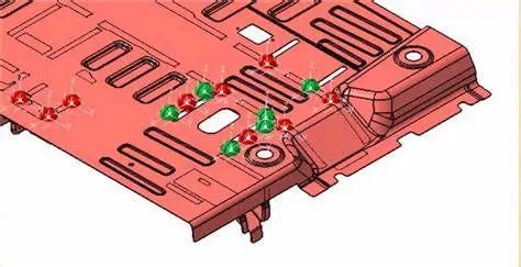
ANS:- Clamp plan is the layout of position of various clampings. For better accuracy we need our panel in accurate accurate position and Orientation as well it must be rigidly fixed. This plans includes the exact position of pins, clamp, dump rest,etc. For accurate handling of panel we must design our fixture firmly.
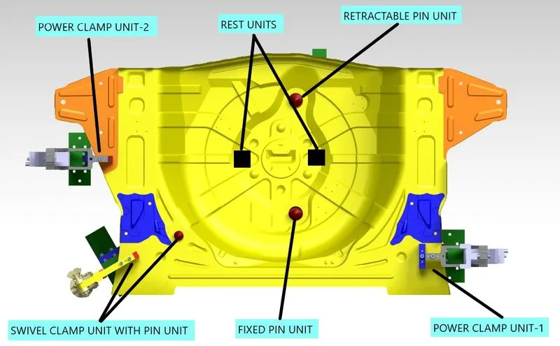
For designing of fixture to hold panel we use 3-2-1 principle. (3)= It indicates minimum three locators or supports needed underneath of panel. Panel must Firmly rest on three locators. It should not be tilted in any direction. These three locators combinely restricts one translational and four rotational degrees of freedom. So three locators restricts total 5 degrees of freedom. (2)= After this we have to use a circular pin in a circular hole. It will restrict four translational degrees of freedom. (1)= At last we use a circular pin in a slotted hole. It will restrict two rotational degrees of freedom. In this way we have to design our fixture so that panel will Be in position firmly and we can do our robotic work or manual work. Once panel is fixed and if we change in clamp plan it may lead obstruction to weld gun or operator. This may cause inaccuracy in panel and may lead to serious issues.
5. What is the purpose of a Layout?
ANS:- The purpose of layout is to know the space constraints in assembly line. While designing fixture we need to consider this layout and designed fixture accordingly. Layout contain flow of panel in assembly line as well the position of robots and their working area the position of operator is also present in the layout it also contains loading and unloading positions of panel following information layout provides:-
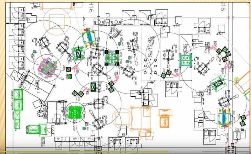
1. station pitch:- Distance between two stations
2. Loading and unloading sequence:- This provides entry and exit point of panels over the stations so we can design our fixture accordingly
3. Flow of parts:- It provides flow of different parts that we use in assembly in industry
4. Robot stations:- This information provides position of robots in assembly line as well their working areas so that we can design our fixture and avoid obstruction to the robots
5. Accessories position:- We may need interchangeability of tools while working. Layout provides us information about position of tool changer and tip dresser. So we can design our fixture according to this information and save time while changing or dressing of tool
6. Subassembly links:- This information is very useful while assembly
7. Platform height
6. What is Ergo data?
ANS:- Ergonomics gives us information regarding human behaviour patterns, their movements and their comfort positions. Ergo data provides us loading and unloading height, position of controls, switch. By compiling this data we need to design our fixture according to human comfort so that operator gets physical and mental relaxation. Operating of machine must not be a difficult task. While designing controls likely lever arm, switches we have to keep in mind height of operator. The position of arm while operating machine must not be in a congested position.
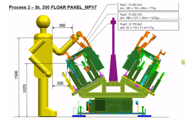
Different companies have different standards of ergonomics. Every human being can work better in their comfort zone. Instead of discomfort situations of operating machine ergonomics provides operator comfort situation and we can get a better output. Without ergonomic study design of fixture may leed to stressful and dangerous life for operator. While designing we need to consider different people with variable age height and ability. We can just optimise ergonomics for all types of people.
7. What do you understand by Weld study?
ANS:- There are mainly 3 types of welding processes that we use in BIW domain namely resistance welding, arc welding and fusion welding. Depending upon the application and position of the component to be welded we use different type of welding process.
Resistance welding:- There are 3 types of resistance welding as follows:-
1. Spot resistance welding:- This type of resistance welding can use in intermediate welding. In this type welds are in the form of spots. This is not leak proof welding but welding time is low so welding speed increases for wedding purpose. Current and pressure are applied at localised point with the help of electrodes. Weld is produced between interface of two parts that are to be joined.
2. Projection resistance welding:- This type of welding is similar to the spot resistance welding but electrode of the projection welding has special type of shape according to the Part to be welded. This is costlier method than spot welding. But in this case resistance welding happen throughout the shape of the electrode rather than at the spot.
3. Seam resistance welding:- This type of welding is use for continuous weld. It has electrodes in the shape of rotary wheels. Pressure and current is applied with the help of periphery of both Rotary wheels. As long as workpiece available we can weld throughout the length.
Arc welding:- In arc welding we use consumable as well as non consumable type of electrode. This is stronger joint than resistance welding. But it is a slow process compared to resistance welding.
1. Manual arc welding:- In manual arc welding we use consumable type of electrode the electrode. Itself electrode is coated with flux so while welding, heat is created by electrodes and melts metals to be welded as well filler gets added with consumption of electrode and flux provides protection against oxidation.
2. Metal inert gas welding:- MIG wedding uses consumable type of electrode which is filler as well. In this case for protection purpose we provide inert gas. Most of the time carbon dioxide is provided to protect weld against oxidation. Electrode spool is mounted over welding machine which continuously rotate as the welding progresses. So this method is easy to adapt in automated welding and robotic welding.
3. Tungsten inert gas welding:- In this type we use non consumable type of electrode which is made up of tungsten. Filler is added externally and argon is provided as a inert gas for shielding purpose against oxidation. This welding process is slower than mig welding. For better quality of welding co-ordination between both hands of operator is must.
As we can see there are different type of welding processes available for different applications. In weld study we discuss about which type of welding is suitable and on which location welding has to be done. Depending upon the thickness, part size, requirement of weld type we can choose welding process. Different welding processes uses different type of welds guns. So according to the space available for weld gun we can choose welding processes. In very narrow space we can't do TIG welding as it needed both hands coordination for better welding. While in case of large size of work pieces we can't use resistance welding.
Depending upon the priority and possibility of welding spots there are 2 types of weld spotting positions:-
1. Geo Weld points:- These are the first points to be welded. This points may be decided because of priority or possibility.
2. Re spot Weld points:- These points are remaining points after Geo weld points. Usually these points are welded after small assemblies has been done.
8. What are the criteria for percentage completion in the designing stage? Explain it in detail
ANS:- Percentage completion criteria is followed in design projects to know the exact dispatch date and progress of the project. It is also used to maintain workflow in design stage. This criteria is followed throughout the design stages stages and dispatch stages. Following are the criteria involved in percentage completion:-
1. 0-25%:- This is input stage where we get all the information needed for the design from the customer. We also build our design concepy in this stage. If the design is completed within the specified time it shows 25% of the project is completed. if we fail to maintain the deadline our project may get delayed.
2. 25-40%:- In this stage we need to get approval for the design. We also have to check simulation for the concept we made. If customer suggest some changes we have to work on that. If design got approval from customer end, it means our 40% work is done.
3. 40-85%:- After got approval from the customer end we need to finalise our design. After freezing of design we need to 3D detailing as well as 2D detailing of CAD models. At this stage we have to prepare with BOM and other documentations.
4. 85-100%:- At this last stage we need to check every detail in design and overcome if there is mistake. Preparation for the dispatch is to be done.
9. Brief about "Output" in design?
ANS:- The output in the design is 3D models and drawings units can be categorised into 2 types as follows:-
1. Utilise tools in this case multiple units are assembled on a single base due to multiple units present on a single base. We have to provide 2 types of sheets as follows:
a. Key sheet:- This is the detailing of positions of units present on base plate.
b. Layout sheet:- This is the detailed drawing of individual units. All the components of each unit is detailed on this sheet.
2. Non-utilized tools:- This are the stand alone components in this assemblies does not involved so this components can be detailed on layout sheet only.
The end product of the design must compile with the following points:-
1. Design of fixture must be simple and economical
2. The maximum number of approved standard parts by customer is to be used
3. Design must be ergonomically suitable for the use
4. It must fulfill the standard safety requirements
5. The weight of the moving parts must keep as minimum as possible
6. For the adequate error proofing we have to provide proximity sensors and other parts which ensures minimum errors
7. The designed fixture must be controlled and damage free handling
8. All the parts must be simple in design with adequate strength
9. Validation of all of weld positions and clamps is must
10. Motion control provisions are to be provided for every moving part
10. What do you understand by structuring a design tree? How does it reduce errors during the design process?
ANS:-
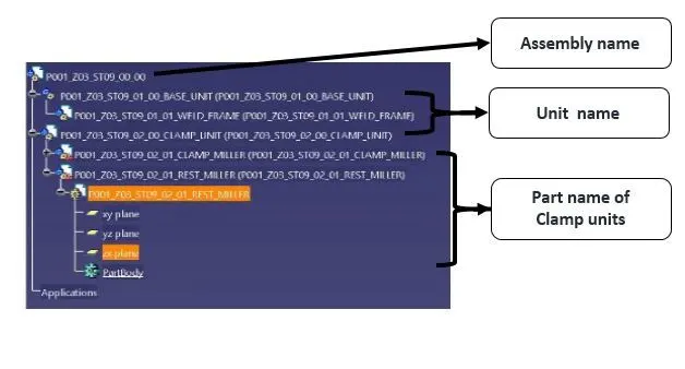
1. Structuring a design tree involves systematic naming of parts, units and assemblies
2. Every company follows specific standards of structuring
3. This helps us to avoid errors during designing, assembly, inspection and manufacturing of components
4. It is important process have is it avoids mistakes while identifying components
5. Well structured of a design tree provides information regarding identifying a specific part and its connection with assembly
6. It helps us distinguishing very similar components but assembled in different assembly
7. So while manufacturing operator can understand the difference between very similar components and where it belongs
8. If Structuring of design tree is not systematic then it may create confusion while assembling and leads to the rework of components
9. Proper naming of part units and fixture gives us information to which assembly zone it belongs to
10. It helps us in identifying number of items in a particular assembly and identifying similar items in a particular assembly
11. What are Units? Mention 5 types of units.
ANS:- Units are smallest assembly of various components. Each unit performs small different function but combining all the functions gives us extraordinary results. There are two types of units as follows:-
a. Unitised tools:- These are little bit complex assembly. multiple units are placed on a single base. So for the detailing of these units we have to prepare two sheets. Following up the two types of sheet that we need to detailed
(1) key sheet:- It defines list of units present on a base. It also defines positioning positioning of each unit over the base.
(2) Layout sheet:- It includes detailed drawing of each unit with its components.
Unitised tools also has two types as follows:-
(1) simple units:- This units are simple in the designing and assembly. It includes following types of units:-
a. Rest unit:- As the name suggests the component or panel just rests on this unit. This unit does not include any complex geometry. It just supports panel to be rest. This unit includes blade, riser and Myler. It does not include any complex components.
b. Fixed pin unit:- This unit include a fixed pin. This pin works well for locating a panel in correct position. It also does not include any complex assembly as pin cannot be moved.
c. Retractable pin unit:- This unit is similar to the fixed pin unit except, the pin is of retractable type. We can move pin with the help of cylinder attched to it.
d. Rough Locator unit:- This unit defines correct orientation of panel. It guides operater to locate car panel. It is placed at edge of the car. It's upper edge has angle of 30-40 degrees outward and rough locator placed 2-3 mm away from car panel. So while loading of panel from upper side it guides the operator for perfect postion and orientation of panel.
e. Sensor Unit:- This unit includes sensors to sense the position of panel. With the help of various sensors (mostly proximity) signal is collected and fed to PLC. PLC processes the signal and signals for the next action.
f. Base Unit:- It is base for all units. All the units are mounted over base unit.
(2) Complex Units:- This units are complex in design and assembly. This unit does work which other units cannot do. It includes following type of units:-
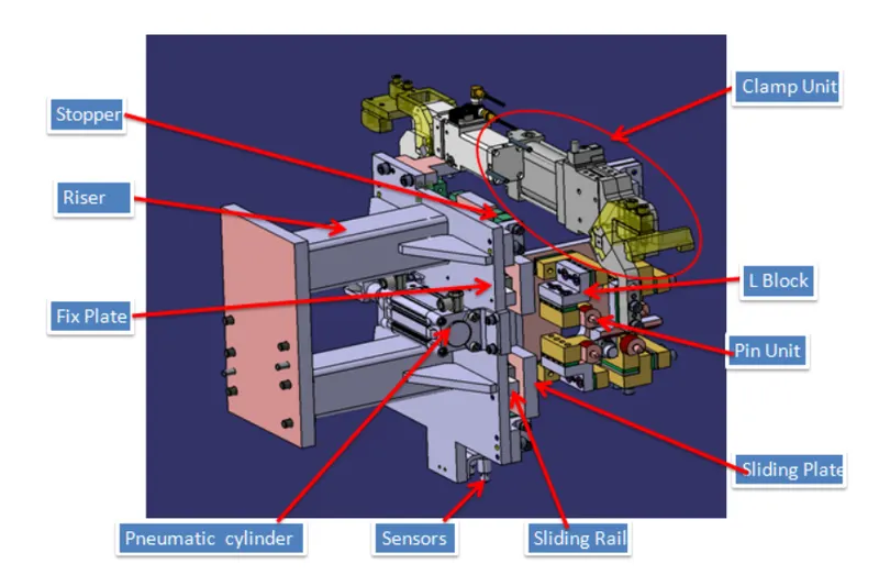
a. Slide unit:- This unit is use where we have some geometrical constraints. It has sliding mechanism with position locking unit.
b. Dump unit:- This unit holds panels which cannot be hold in a normal way.
b. Non-Unitised Tools:- This are simple standalone components. This units are simple in design. So Keysheet is not required. Detailing can be done in layout sheet only. It includes following type of units:-
1. Take out trolly:- This unit performs transportation of panels. It is use for moving panel from working station to inspection cell.
2. Stands:- There are various types of stands gluing, docking, pedestal, etc. Each one does simple but important function alone.
3. Cnveyor:- This use for continuos transporation purpose.
4. Grippers:- This device is use to hold car panel. It is fixed at manipulating end of robotic arm.
12. Describe Fixed Pin units & their purpose?
ANS:- This is unitsed tool of simple type. So its design and working is simple. This unit include a fixed pin. This pin works well for locating a panel in correct position. It also does not include any complex assembly as pin cannot be moved. It includes following parts in assembly:-
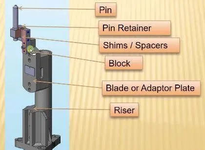
a. Pin:- It is most important component. It locates a panel by mating with hole in a panel.
b. Pin retainer:- It supports panel for retaintion. It supports pin against weight of panel. It has step to lock the rotation of pin. It is finely machined at a surface where pin will be engaing. It is either make or standard part. It is fixed to a block/L- block.
c. Block/ L- block:- This are use to accomodate adjustments in dimensions after manufacturing of unit. Adjustment can be done in two direction with the help of shims. For two way adjustment block is made in L shaped, so called as L- Block.
d. Shims/ Spacers:- This are use for maintaining close tolerance, If after assembly there is minor error in location of components, by adjusting shims we can reduce that error.
e. Blade:- It connects all parts of unit to riser. It is just a plate like part. It may be standard part or make part.
f. Riser:- Riser connects blade to base unit. All parts of units attached to riser. Riser may be make or standard part. It increases height of pin from base unit.
13. What are the different parts of a fixed unit?
ANS:- Following are the parts of fixed unit:-
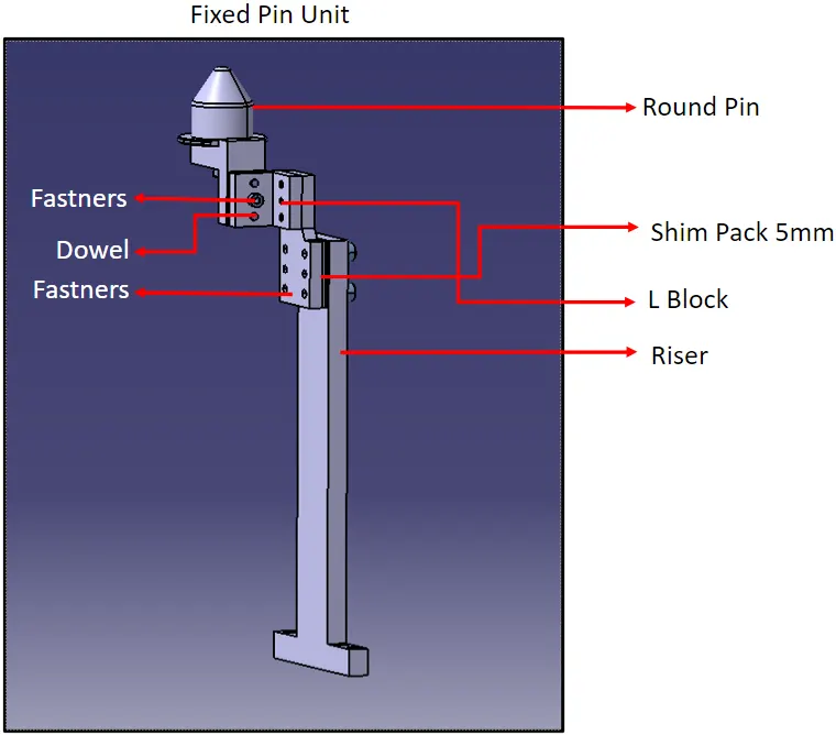
a. Pin:- It is most important component. It locates a panel by mating with hole in a panel.
b. Pin retainer:- It supports panel for retaintion. It supports pin against weight of panel. It has step to lock the rotation of pin. It is finely machined at a surface where pin will be engaing. It is either make or standard part. It is fixed to a block/L- block.
c. Block/ L- block:- This are use to accomodate adjustments in dimensions after manufacturing of unit. Adjustment can be done in two direction with the help of shims. For two way adjustment block is made in L shaped, so called as L- Block.
d. Shims/ Spacers:- This are use for maintaining close tolerance, If after assembly there is minor error in location of components, by adjusting shims we can reduce that error.
e. Blade:- It connects all parts of unit to riser. It is just a plate like part. It may be standard part or make part.
f. Riser:- Riser connects blade to base unit. All parts of units attached to riser. Riser may be make or standard part. It increases height of pin from base unit.
14. What is the purpose of making a Rest unit & describe its parts?
ANS:- This is simple unit use for resting of panel. It supports the car panel. It ensures that panel will be in proper orientation while woring. It is made up of following components:-
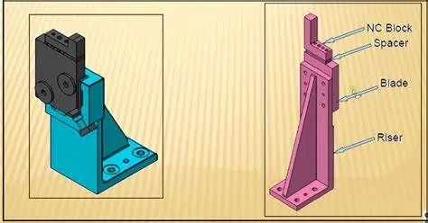
a. NC Block:- It is sa simple block on which panel rest. It just contains dovel holes for mounting on blade.
b. Blade:- Blade in a simple plate like paft. It connects other parts to the riser. It may be standard [part or make part.
c. Shims/ Spacers:- This are just for adjustment of postion after assembly. It contains diffrent thickness of shims.
d. Riser:- Riser is use to connect all the parts to base unit. It also increases height of a unit from base. It may be standard or make part.
15. What are the basic fundamentals to design a Sensor unit?
ANS:- A sensor unit is designed to sense the car panel with the help of elctronic sensor. It contains proximity sensor to sense car panel. Sensor collects signal and sends to PLC where it is processed. After processing PLC gives command for next process to excecute. Unless and until sensor do not send signal and PLC admit it as a perfect signal, other processes will not be take place. This safeguards the panel to be work on. Fundamentals of sensor unit design are as follows:-
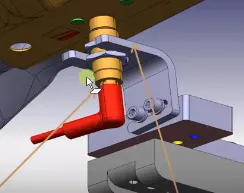
a. Every sensor must be mount such that it will be 3 way adjustable.
b. Every panel which is to be welded in a tool must be sensed.
c. Each panel must be sensed with 1 or 2 sensors. Depending upon size of panel number of sensors may increase.
d. Position of sensors must be placed diagonally opposite.
Types of sensors used in general:-
a. Proximity sensor
b. Laser Sensor
c. Photo electric sensor
16. What is a Rough locator unit & what are the basic fundamentals to consider while designing it?
ANS:- Rough locators are parts designed to locate panel. It helps operater for correct locating of panel on pins. It can be of standard part or make part. Following are the fundaments of rouch locator for design:-
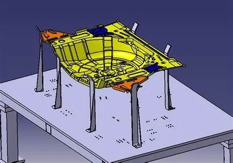
a. It should be designed with a bend at upper end. It has opening of around 30-40 degrees outward.
b. Rough locator should start guiding panel before 10-15mm before engagement of panel with pin unit.
c. It should be 2-3mm away from panel.
d. It must be placed at the edge of the car panel to which it has to guide.
e. Rough locator should be placed at same angle that of car panel.
f. Rough locators should be designed with two slots for easy mounting over base plate.
g. The slots should be in direction of car part guiding.
17. What is a Base unit and describe it's parts?
ANS:- Base unit is designed to mount all other units like pin unit, clamp unit, rest unit, rough locators,etc. It generally levels all the units from same height. It also use to mount other parts than units like penumatic valve, trunking cable, etc. It contains various parts as follows:-
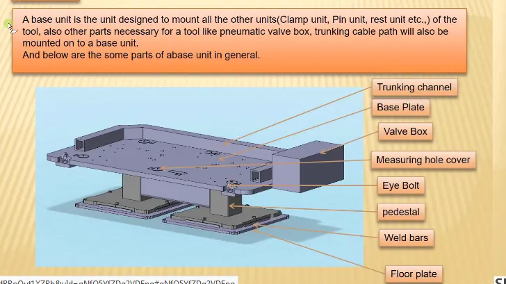
a. Trunking channel:- It is channel for enclose wiring over the base plate. Other than elctrical wiring pneumatic pipes and hoses can also be enclosed in trunking channel.
b. Eye bolt:- It is use to lift the base unit. With the help of chain or rope we can lift base unit from eyebolt.
c. Valve box:- It is box for different actuation valves. It will be easy for operator to operate from a single place.
d. Pedestal:- It connects base plate to weld bars. Pedestals increases height of base plate.
e. Weld bars:- It connects between pedestal to floor plate.
f. Floor plate:- It is mounted over the ground. It kept intact whole assembly of base unit to ground.
g. Measuring hole cover:- This are covers for measuring holes.
18. What is a Dump Unit and what are its functions?
ANS:- Dump unit is actually use for holding purpose of panel. which normal units cannot do. It falls under category of complex units of unitised tools.
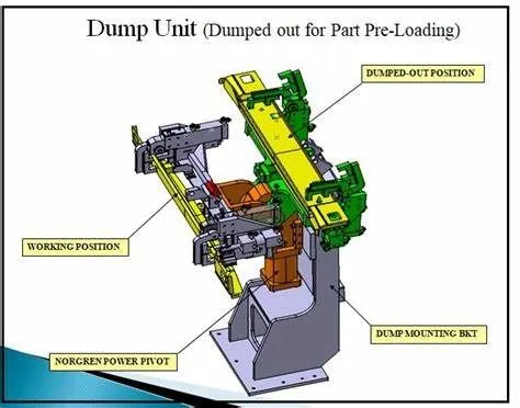
Function of dump unit:-
If we have constraints while holding a panel in normal way, we can hold it with the help of dump unit. It has cylinder, clamp unit mounted over it. So this makes designing complicated.
19. What is a Slide unit? Mention where Slide units are commonly used.
ANS:- This units are also use in cases where there is geometricals constraints for using normal units. In places where we cannot use normal units to hold panel, slide unit can be used. It falls under category of complex units of unitised tools. It has following parts:-
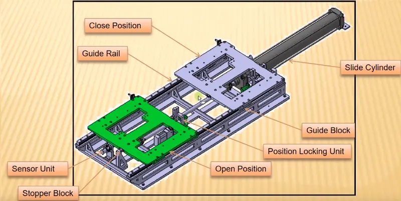
a. Guide rail:-This guides the unit. Unit can slide over the guiding rails.
b. Slide cylinder:- It provides movement to the unit to slide on rails.
c. Position Locking Unit:- It lock the unit in a specific required position.
d. Sensor unit:- It detects correct required position of unit.
e. Stopper block:- Stops the excessive sliding movement of unit.
f. Guiding Block