Week 9 - Attachment Feature Creation - Challenge 2
AIM:
To create screw boss and dog house on the coin holder component.
OBJECTIVE:
The engineering features which follows the proper design standards and also analyse the manufacturing feasibility of the component.
SOFTWARE USED:
CATIA V5
SCREW BOSS:
The screw boss is a feature used to add the fastener that can couple or mate two separate components together. Generally, they are used with self threading screws. There are certain monitoring standard equations to be followed in the screw boss design.
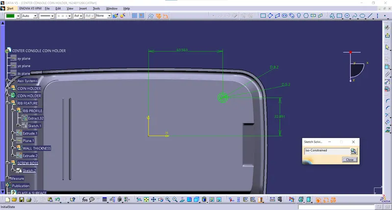
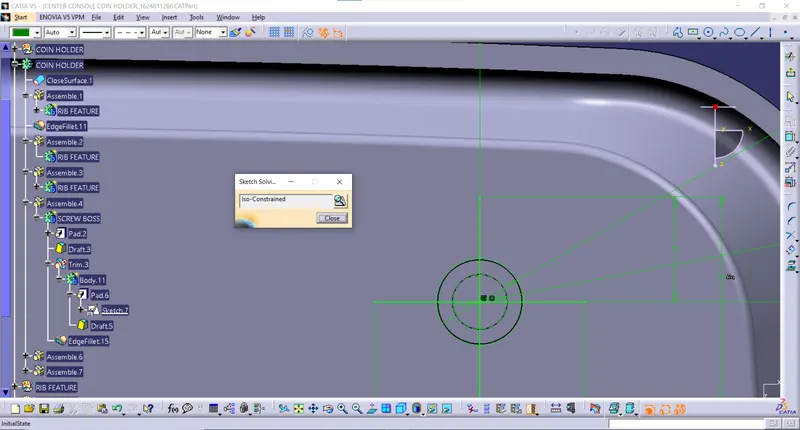
Initially, the screw boss profile is created. The design here is for an M6 fastener. Then the wall thickness is determined by the equation,
`Outer dia= 0.3*t`
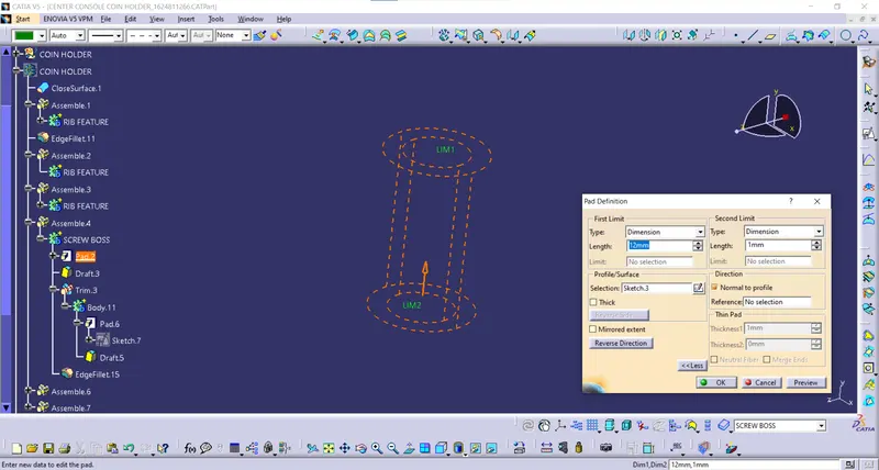
Then the profile is extruded above the the surface using the pad command.
Then the outer surface is drafted along the main tooling direction
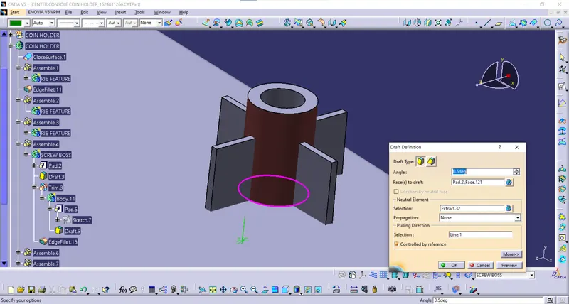
Rib support is provided for the screw boss considering the height it has been padded. The profile is as follows
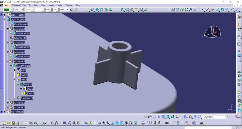
They are then padded and union trimmed to the screw boss
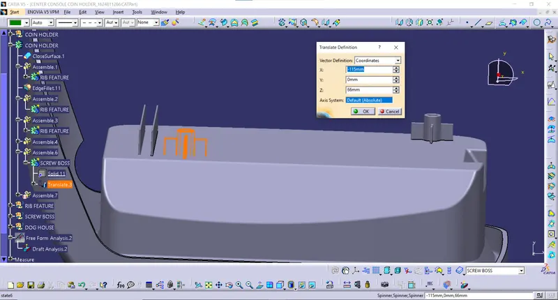
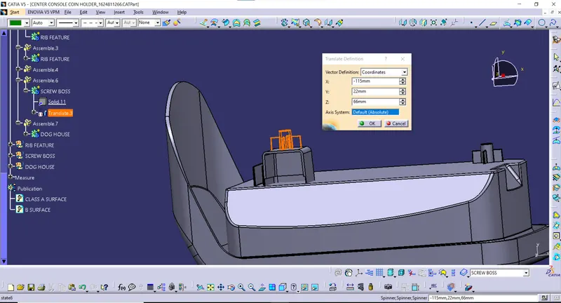
Once after the fillet definition to the edges the screw boss along with the ribs are asssembled together and then they are translated diagonally on the B surface of the component.
DOG HOUSE:
The dog house is another major feature in the B side, as the name suggests it houses an cavity on top of which the screw boss is mounted. Generally, when the distance is more, instead of increasing the screw boss heigh which will reduce the strength of the feature also create sink marks, rather a dog house can be designed and the screw boss mounted on top of it.
A rectangular profile is created at first and then extruded along the Z component. 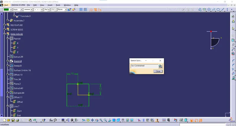
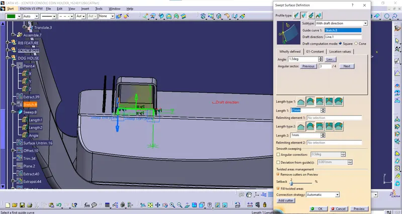
Here we are using the sweep component to make the drafting along the extrusion itself.
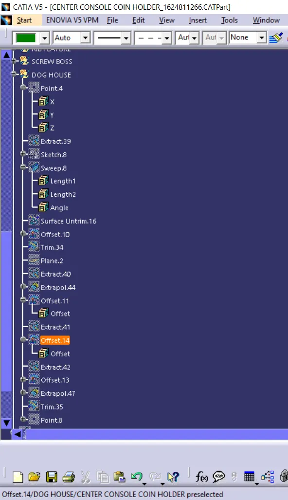
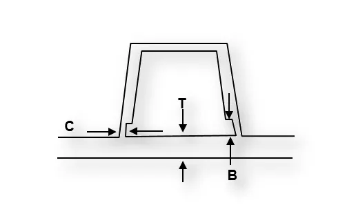
To create this cut section we are making the extract of the B surface and then giving a offset for the desired length, 3 to 6 mm being the standard, we are giving an arbitrart 4 in between.
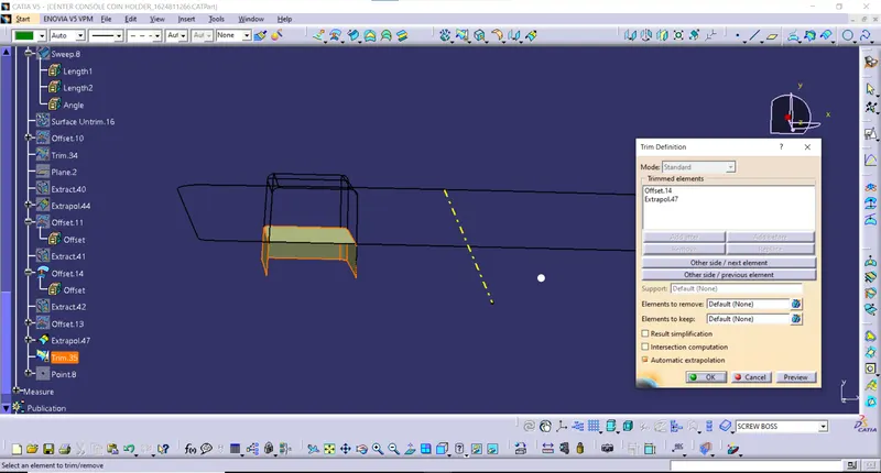
Once the extrapolation, offset is given we are splitting the part body with the above trimmed profile.
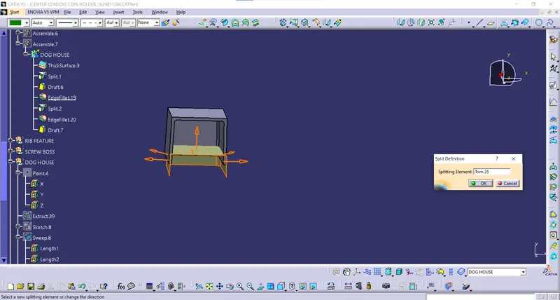
Resulting in such a profile desired. Then this is assembled into the main component.
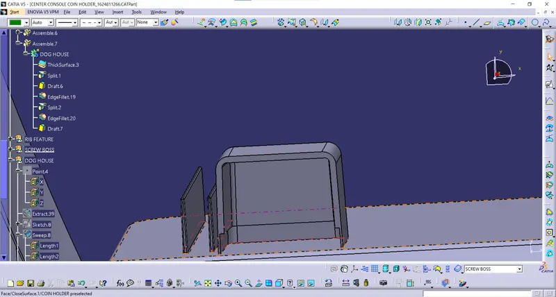
Then the screw boss is translated to the feature it above the dog house.
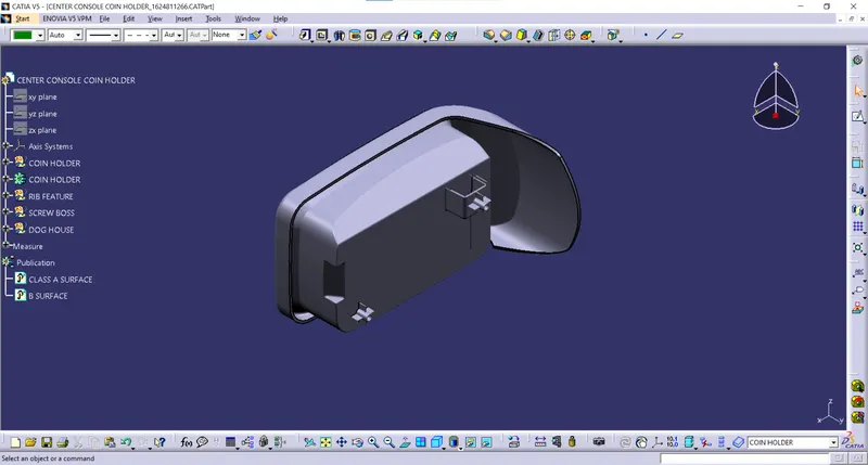
FINAL COMPONENT:
Isometric View
Front view
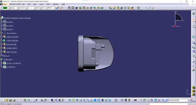
Side view
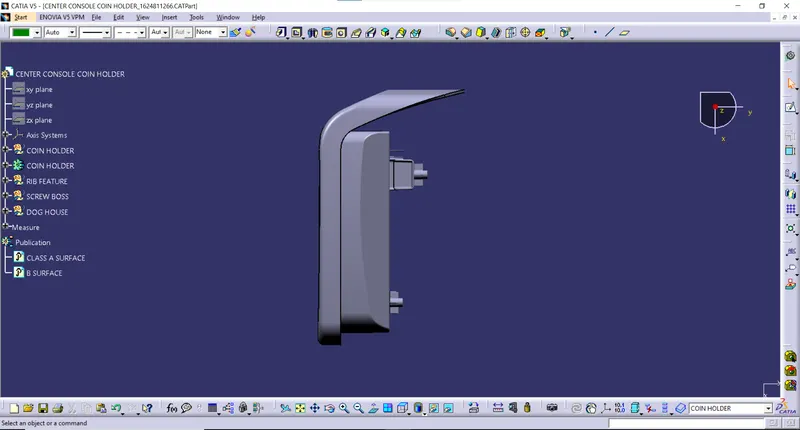
Multi view
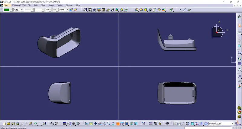
DRAFT ANALYSIS:
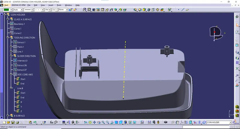
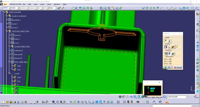
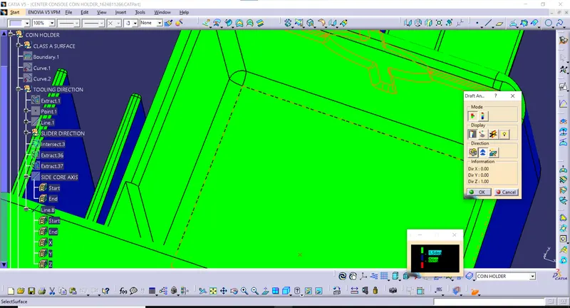
As we can see the screw boss and the dog house outer walls are getting cleared in the main tooling direction itself but the inner cavity of the dog house needs a side core which is again a undercut.
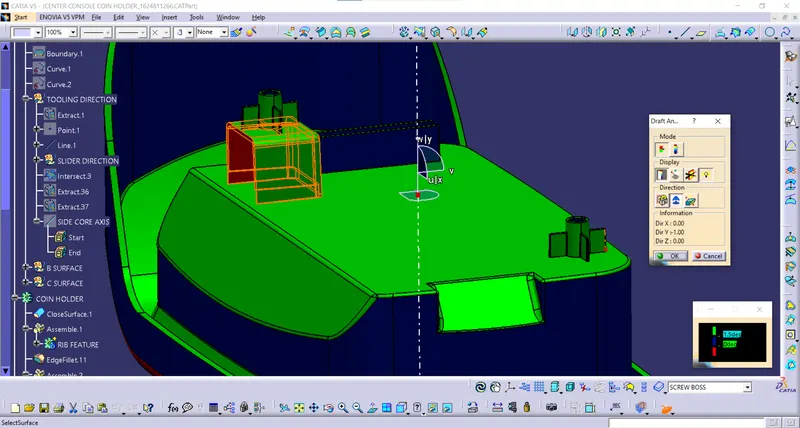
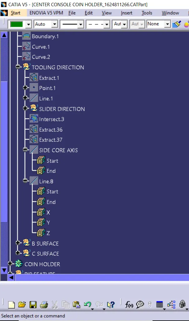
Hence, we are defining a tooling axis for the side core.
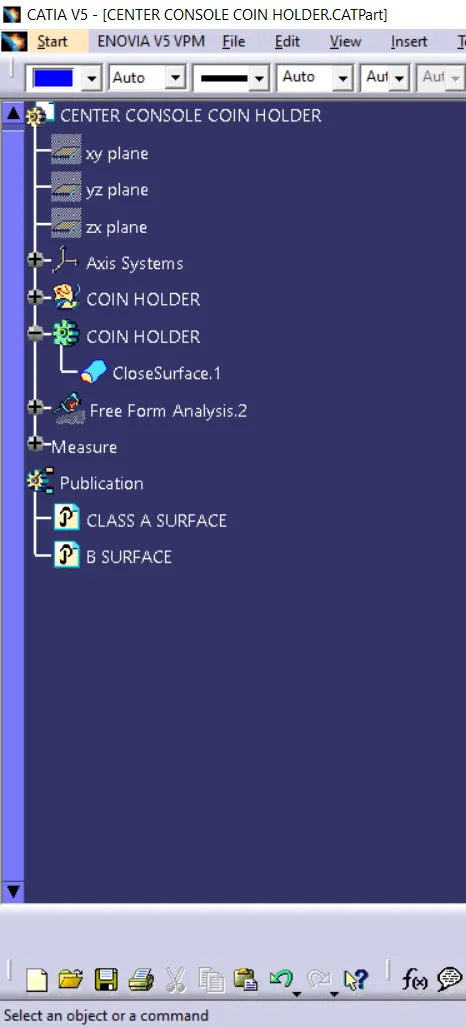
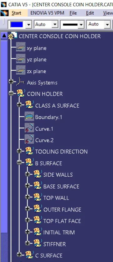
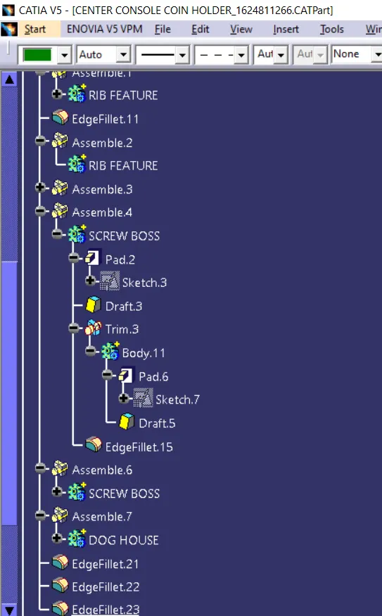
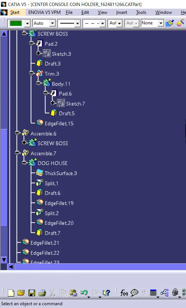
TREE STRUCTURE: