Week 9 - Attachment Feature Creation - Challenge 2
Aim: To create Door trim plastic component from the given Class A surface and create a Dog house as per the design consideration. To begin with, the tooling axis for the given Class A surfaceshould be created meeting the requirements of the draft angle and at the end perform the draft analysis on the model.
Class A Surface: Class A surface is the asthethic surface that is created through scaning of clay model. This Class A surface is a input CAD model for the part design.
Class B Surface: Class B surface is created in a certain distance according to the thicknesss of the part. Class B surface contains all the engineering components.
Class C Surface: Class C surface joins the Class A & B surfaces.
In this model we have focused on the following things:
- Tooling Axis
- Draft analysis
- Class B surface
- Class C surface
- Making a solid model from the surface
- Creating Dog house
Class A Surface
- The 3D CAD part file of the Class A surface is given. Next step is to check the continuity of the Class A surface. This is to ensure there is no gap between the surface. If any found we must resolve that first.
- Analyse the Class A surface through visual inspection
- To make sure there is no gap in between the Class A surface, we can also check with the help of Join or boundary command.
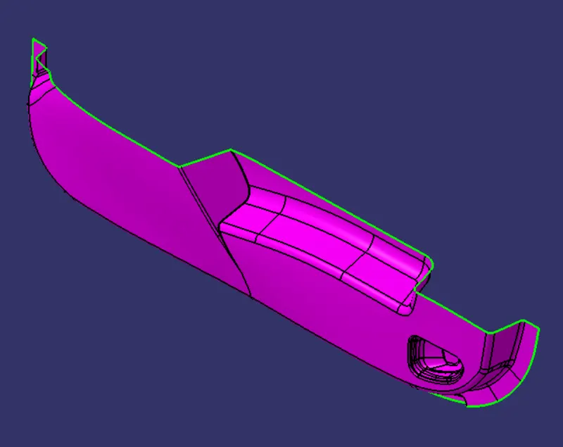
Figure: Class A Surface
Tooling Axis:
- Tooling axis represents the opening and the closing of the mold core and the cavity during the manufacturing of the components. A plastic product designer should consider the best tooling direction to cutdown the cost of the component very less.
- Firstly, Check the best tooling direction for the given surface.
- We can find out the best tooling direction by cross checking all the three axes.
- Here we can find out that the best tooling direction for the class-A surface is along Y-axis direction.
- Next, extract a surface from the Class A surface and create a midpoint on that surface.
- Then from the created midpoint create a line normal to the extracted surface. Thus this created line is "Tooling Axis".
- Tooling axis can also be created by using the bisecting method.
- We create a point on the surface and with respect to that point an axis system is created.
- Using the Intersect option, choosing the Axis system and Class A surface as the first and second element we created an intersect.
- Further, we create two lines along the vertices of the intersect opposite to each other.
- From both lines we create a bisecting line passing through the point created earlier on the surface.
- This bisecting line can be considered as " Tooling Axis".
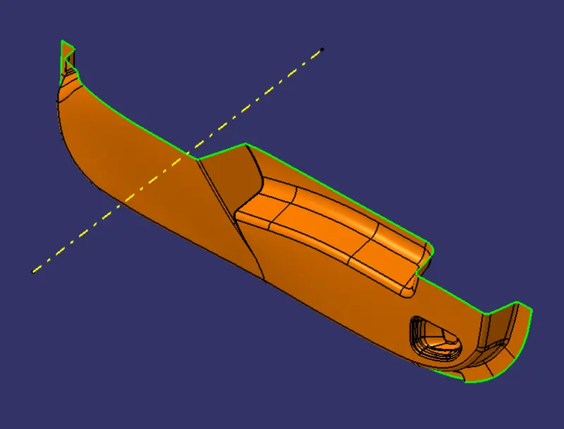
Figure: Class A surface with Tooling Axis
Draft Analysis
- The Draft Analysis is a command enables you to detect if the part you drafted will be easily removed. This type of analysis is performed based on colour ranges identifying zones on the analysed element where the deviation from the draft direction at any point, corresponds to specified values.
- Draft analysis is done after determining the tooling axis, draft analysis is used to check whether the minimum draft is maintained or not.
- Change the view mode of the component to be in customized parameter mode and then select the shading mode as materials.
- Then Using the "Draft analysis" command, click on the compass to define the current drafting direction and lock the compass on the tooling axis and perform the draft analysis by clicking on the Class A surface.
- Click on the analyses under the running point to check the draft analysis on the individual faces. It shows how much draft on specific points when we move the cursor point.
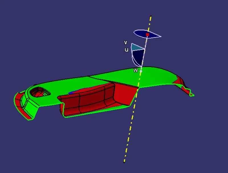
Figure: Draft Analysis of Class A surface
Note: Given Class A surface doesn't provide clear draft and showed it to the tutor before submitting the report.
Class B Surface:
- Offset the given Class A surface to 2.5mm inwards direction.
- From the offset of Class A surface, the new Class B surface formed has few patches as shown in figure.
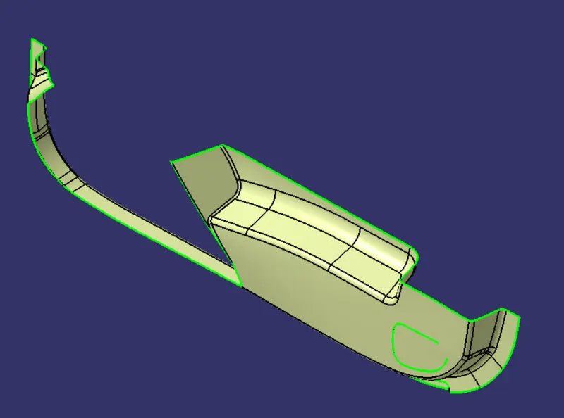
Figure: Class B surfce with Patches
- Rework on the patches and discontinuity of the offset surfaces by individually extracting the surfaces and extrapolating them.
- Finally, apply the trim operation between them and add appropriate fillet.
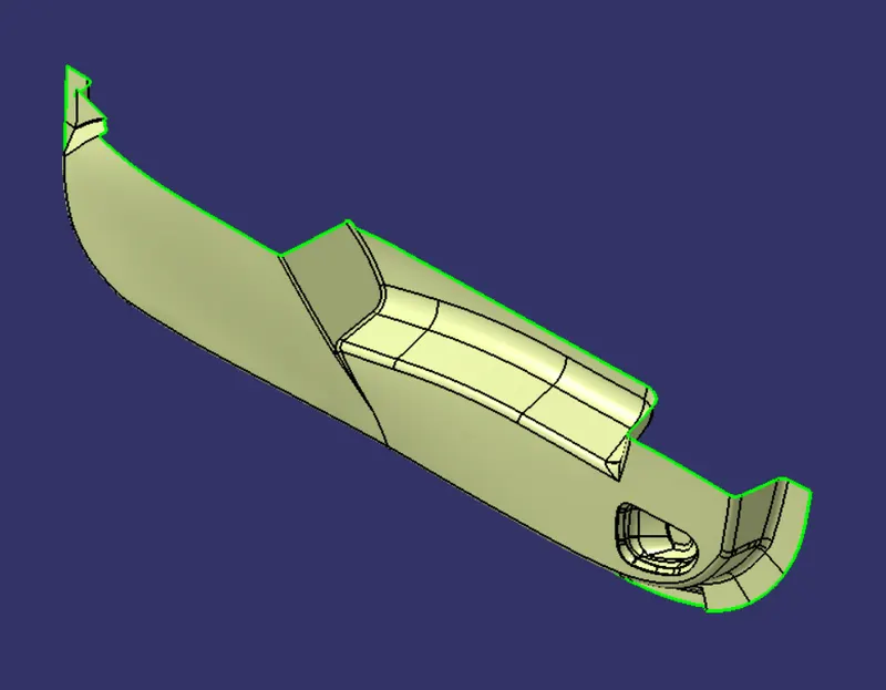
Figure: Final Class B surface
Class C Surface
- Class C surface joins the Class A surface and Class B surface.
- Since it is a complex Class A surface, we perform Sweep operation of 90 degrees with reference to the surface option by creating the outer and inner boundary.
- Finally, we join the Class A and Class C surfaces
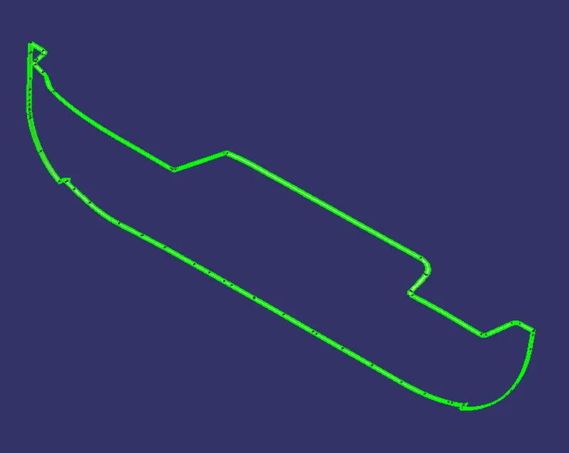
Figure: Class C Surface
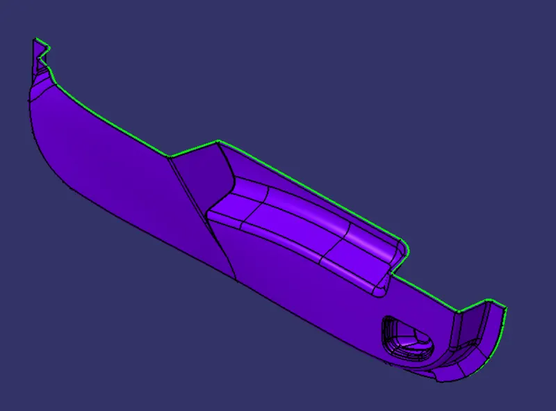
Figure: Class A+C Surface
Final Closed Surface
- Next step is to join the Class A+C surface with the Class B surface to get the final closed surface
- Some error may arise while applying the trim operation as some surfaces may not intersect each other properly.
- We extrapolate those surfaces and apply the trim operation to finally get the closed surface.
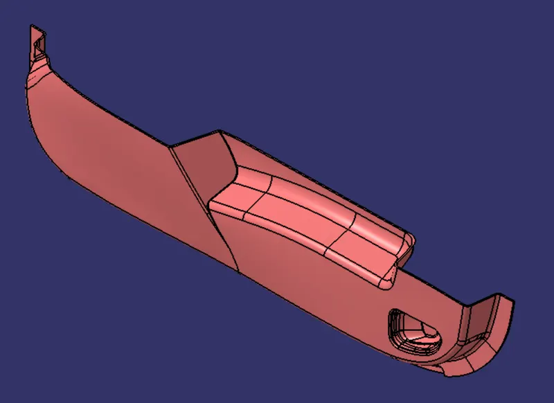
Figure: Final Closed Surface
- Switch to the part workbench then apply " Closed surface" Command on the first closed surface
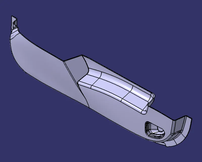
Figure: Final Closed surface in Partbody
Draft Analysis on Final Closed Surface
- Change the view mode of the component to be in customized parameter mode and then select the shading mode as materials.
- Using the "Draft analysis" command, click on the compass to define the current drafting direction and lock the compass on the tooling axis and perform the draft analysis by clicking on the Closed body.
- Click on the analyses under the running point to check the draft analysis on the individual faces. It shows how much draft on specific points when we move the cursor point.
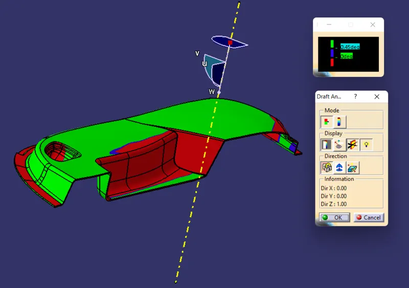
Figure: Draft analysis on the Final Closed surface
Note: With respect to the given Class A surface, the draft of the final closed part body is also not proper. Showed it to the tutor before submitting.
Doghouse:
- To begin with, extract the respective surface of the Door trim on which Doghouse is to be created.
- Create a point on the surface and next create a plane with respect to the above created surface and point.
- Create a positioned sketch of Doghouse on the respective plane.
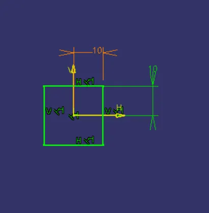
Figure: Sketch of Doghouse
- Next switch to the "Part Workbench" and create a pad on the above sketch to 20mm.
- Next use the Shell Command of 2.5mm on the respective faces of the Doghouse.
- Further, we provide the draft of 1.5 degrees on the outside faces of the Doghouse with its bottom face as the neutral element and Tooling axis as the pulling direction.
- Next, create a Slider axis of the Doghouse such as it is normal to the open inside face of the Doghouse.
- Apply the draft of 0.5 degrees on the inside faces of the Doghouse with Slider axis as the pulling direction.
- At junction of the lower Doghouse and B-Surface we reduce the wall thickness to 1mm and to the height of 4mm.
- Using the Spilt Command on the Part workbench we acheive the required Doghouse structure.
- Next, the edge fillet of 1mm and 3.5mm is provided on the inside and outside faces of the Doghouse.
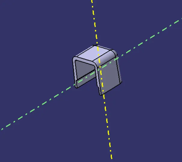
Figure: Doghouse
- Using, Paste special create another Doghouse and translate it to another appropriate point.
- Finally, using Union trim add the Doghouse on the Partbody of the Door trim
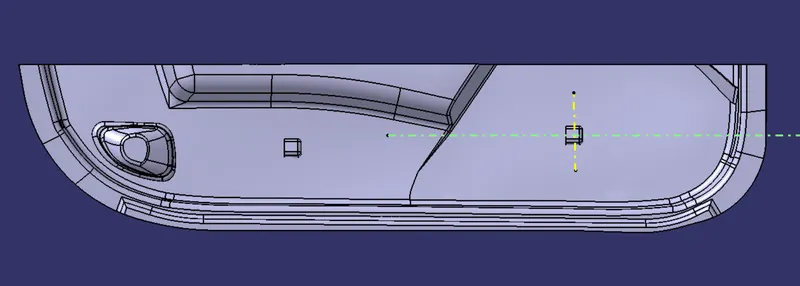
Figure: Door trim with Doghouse
- Finally apply draft analysis on the Final component and also apply draft analysis on the doghouse individually with respect to the Tooling axis and Slider axis.
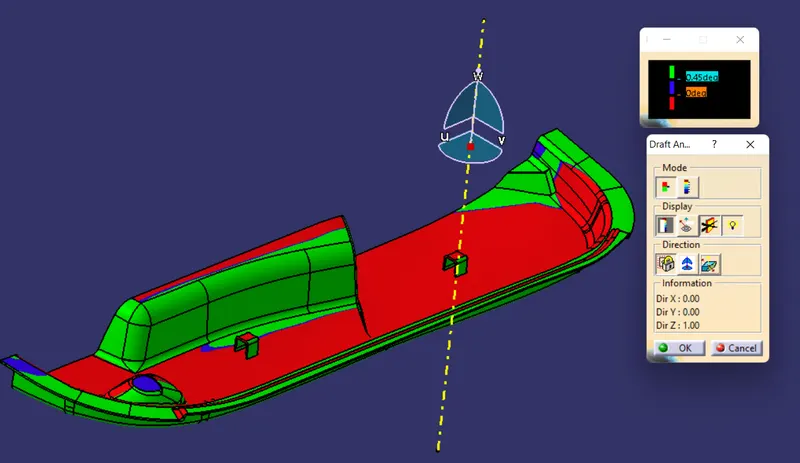
Figure: Draft analysis of final part body with doghouse
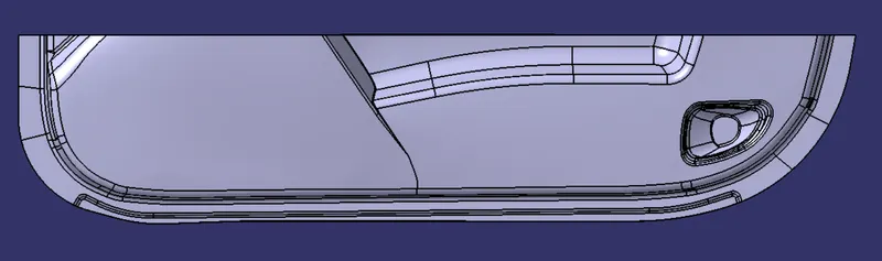
Figure: Front View
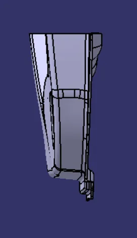
Figure: Side View

Figure: Top View
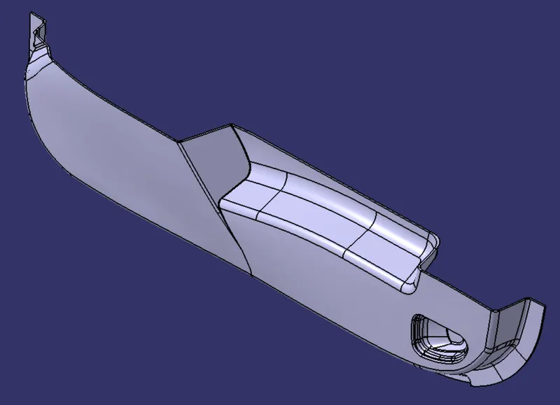
Figure: Isometric View