Week 9 - Attachment Feature Creation - Challenge 2
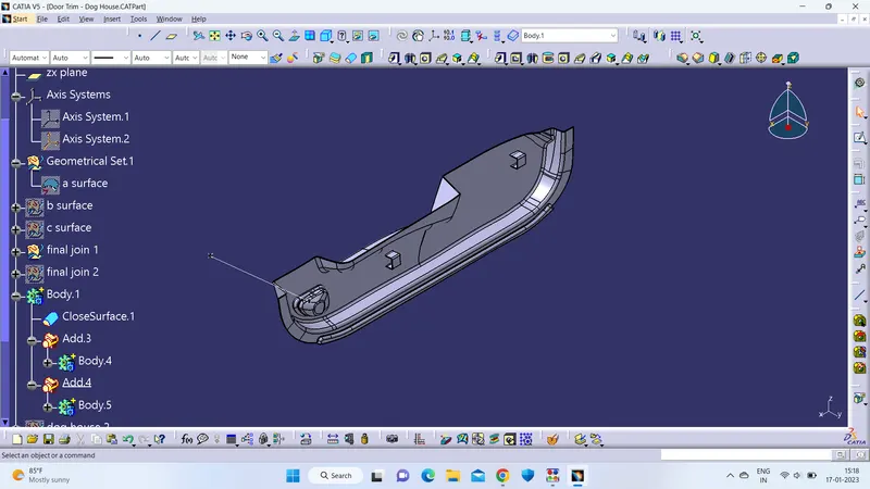
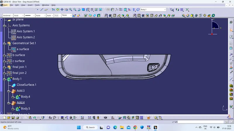
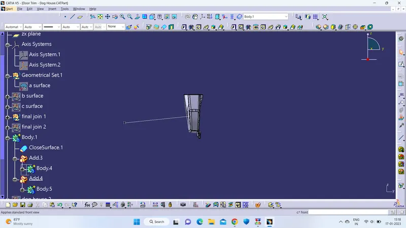
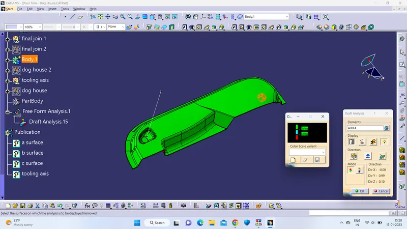
The draft analysis for the component was done with taking the fdrafting axis as the tooling axis and then locked in place. After this was done, the component to be analyszed is selected as the final component and the draft analysis is done. The portion repressented in green shows that the component is 3 degrees with the tooling axis and is ready to be manufactured.
As for the design of the dog house the base measurements of the sketch was taken as a centre rectangle and 12mm for height and width as done in the videos. Then the height was taken as 20 mm as done in the video.
After that the skectch was extruded along the tooling axis and the thickened to get the desired solid component. Then the inner walls were drafted to the minumum 0.5 dgrees along a axis that is perpendicular to the base of the dog house.
Since the thickness of the component was taken to be 2.5mm the thickness of the C portion of the component is said to be 40% of the thickness of the main component then the thickness comes out to be 1 mm.
The height of B is said to be between 3 and 6 mm. So the height of B is choosen to be 4 mm as done in the video.
The inner surfaces of the dog house after C and B have been defined were also drafted to the 0.5 degrees. The fillet was taken out to be 3 mm on the outisde and 1 mm on the inside.
When the final draft analysis was conducted the walls of the dog were parallel to the tooling axis as they have been extruded along the tooling axis.