Week 9 - Attachment Feature Creation - Challenge 1
Aim: To perform the draft analysis on the component.
Procedure:
To perform the draft analysis, we first need to create the tooling axis. We create the tooling axis in the following process;
1: We observe the given A surface design and estimate a tooling axis direction. Since there is a hole in the component and flanges, we cannot use the X and Z axes as this would create the need for a side core for extracting the molded component. We thus use the Y-axis as our estimated tooling direction.
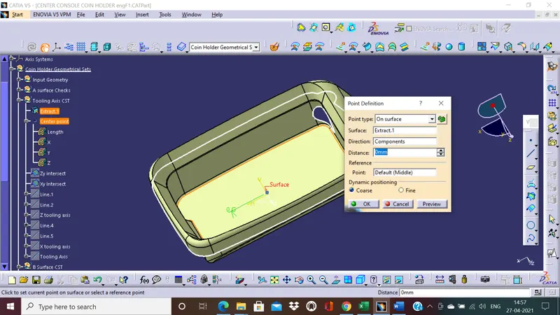
2:We now extract the flat face perpendicular to Y-axis and create a center point on which we will create our new axis system as shown.
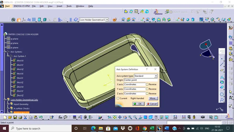
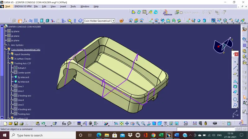
3.After creating our axis system, we need to intersect the XY plane and ZY plane with the A Surface. We are left with the intersect as shown below.
4.Let us first work on the Z direction tooling axis, for this, we use the YZ intersect lines. We extend the lines that we assume will be parallel to our estimated tooling axis using point to point line type.
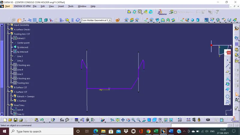
5. After extending these lines, we then bisect them using the center point we have created.
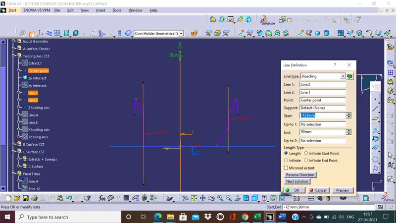
6.Similarly we extend lines that are parallel to the X-axis tooling direction and then bisect those two new lines creating a new line passing through the center point. This new line is our X-axis tooling line.
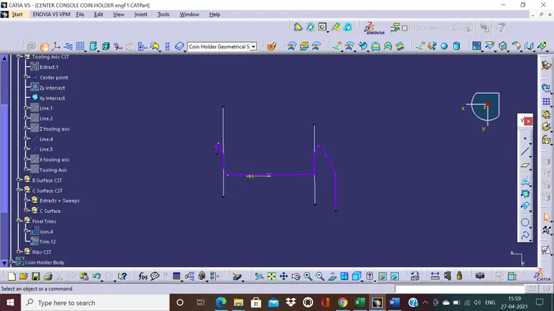
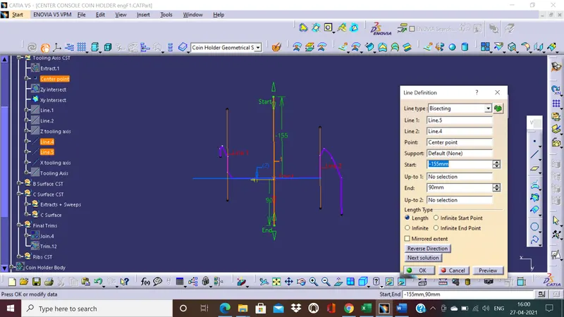
7. Finally for creating the tooling axis, we bisect the X and Z tooling direction axes and pass it through the center point.
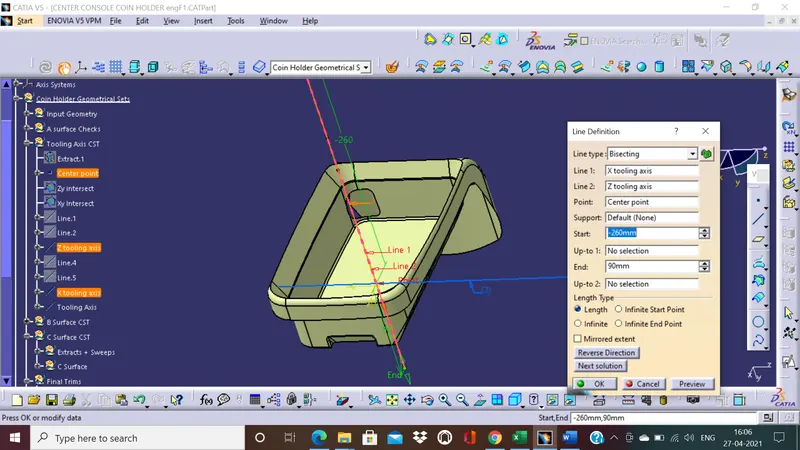
We are now in a position to perform the draft analysis.
Observations:
Color Codes-
Green - 3 and Greater than 3-degree draft angles from the tooling axis
Red- O to 2.999-degree draft angles from the tooling axis
Blue - all negative degree draft angles.
A Surface Draft analysis:
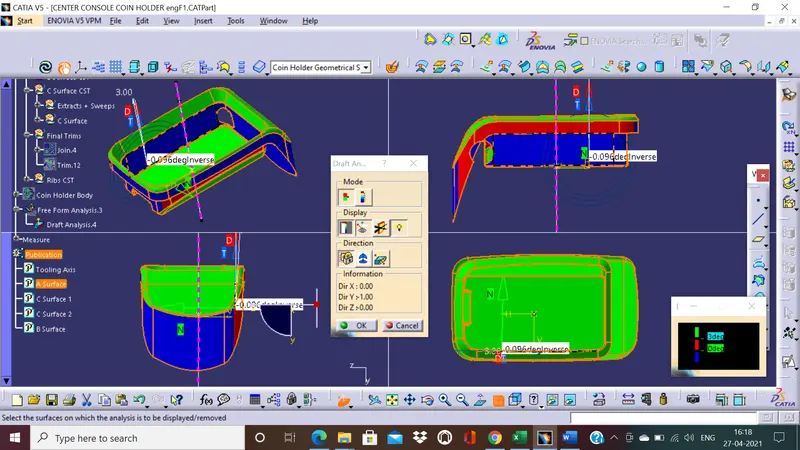
From the above picture, we can tell that the class A surface is not designed keeping in mind, the draft angles.
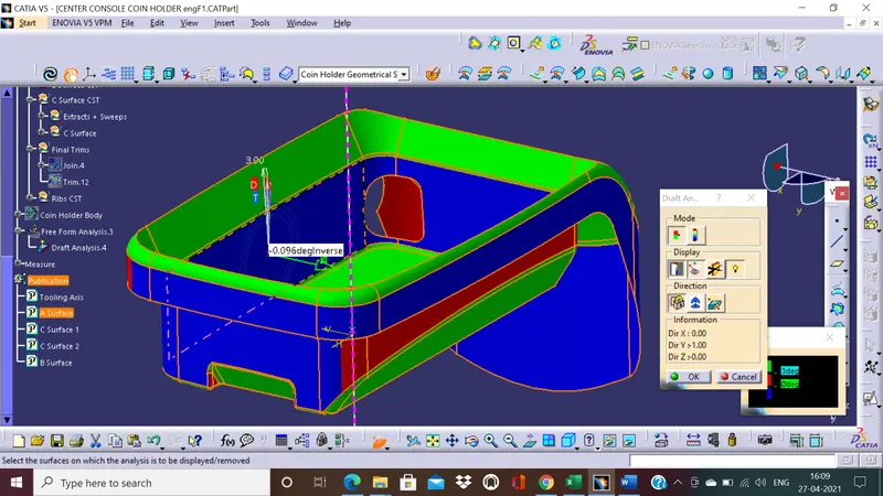
The inner surface side walls are almost completely parallel to the tooling axis.
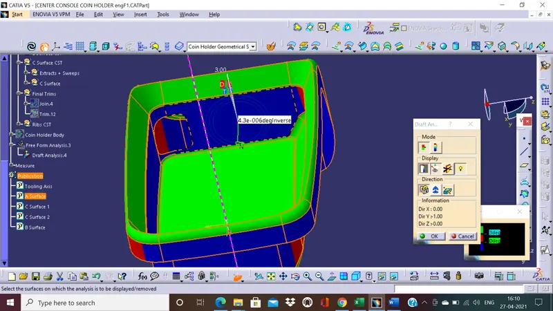
The customer would see this surface and also can feel it with his/her fingers.
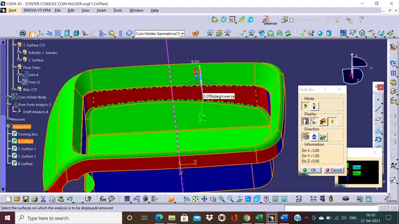
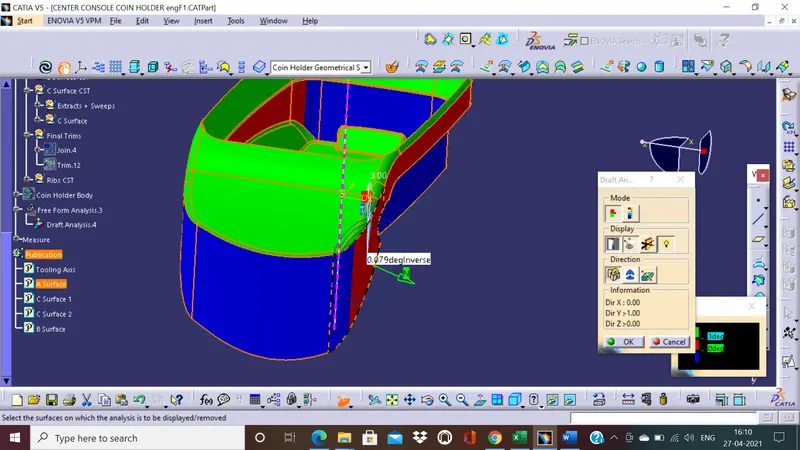
We are seeing draft angles of the range 0.096 to - 0.096 degrees from the tooling axis.
Conclusion:
Class A Draft analysis:
From the draft angles recorded from the tool, we observe color regions in red and blue on the A surface area where the customer can visually see the component. It is advised to redesign the A surface inner surface if not all the surfaces keeping drafting in mind. A draft angle of 0.096 on the inner surface is seen, such areas will have poor surface finish not desired by any customer. The part will have resistance getting out of the mold as well when it is parallel to the tooling axis.
Final component draft analysis:
On the final component, we observe the same problematic transitioning color-coded regions on the inner A surface region. This needs to be changed.
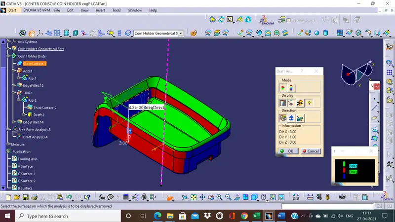
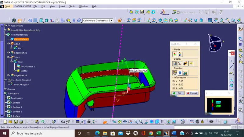
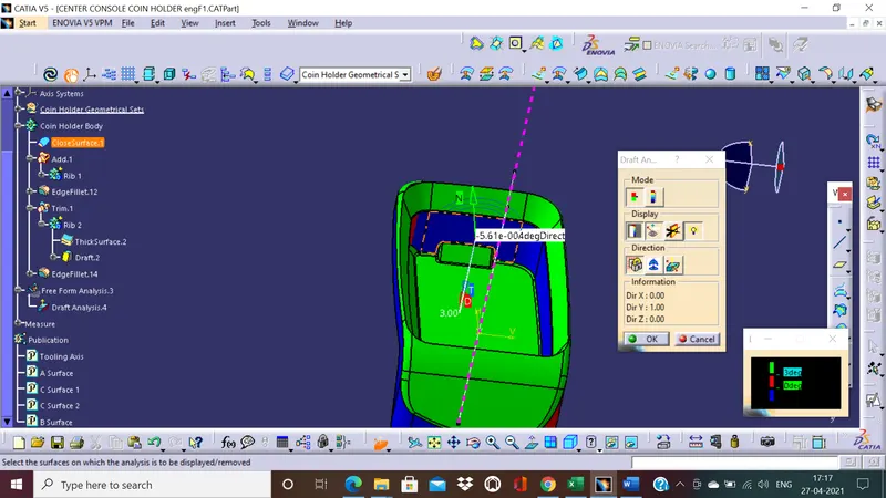
Ribbed Surface drafts:
We have given a minimum draft angle of 0.5 degrees from the tooling axis for our ribs.
It can be seen from the recorded pictures from the draft analysis on the ribs.
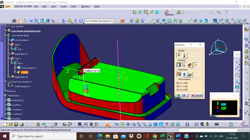
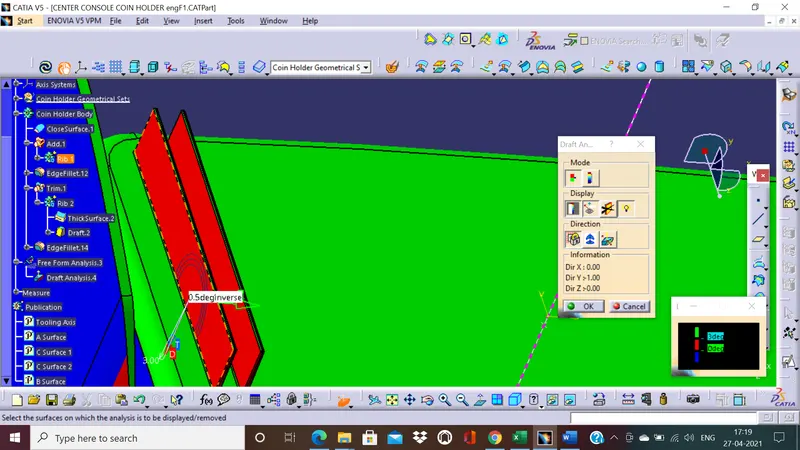
Since the ribs are on the Class B surface, it is very unlikely they will be seen or felt by the customer. The minimum draft angle of 0.5 degrees has been maintained on the ribs and they can be molded.
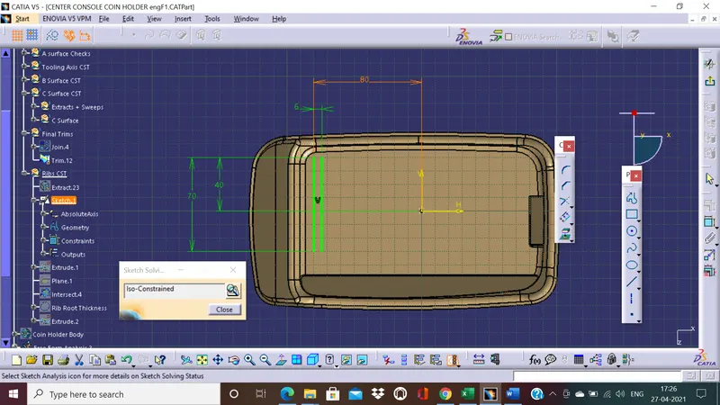
Iso constrained sketches of the ribs:
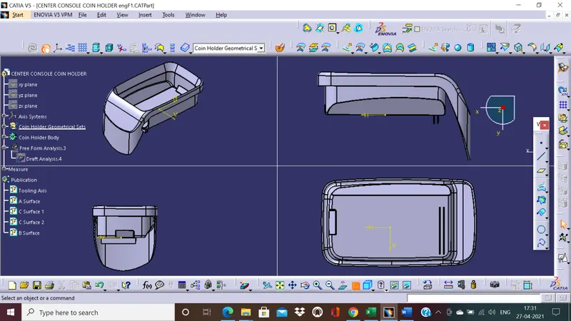
Different orientations of the final component in different Quadrants:
Q1:Left Side view
Q2:Isometric view
Q3:Front view
Q4:Top view
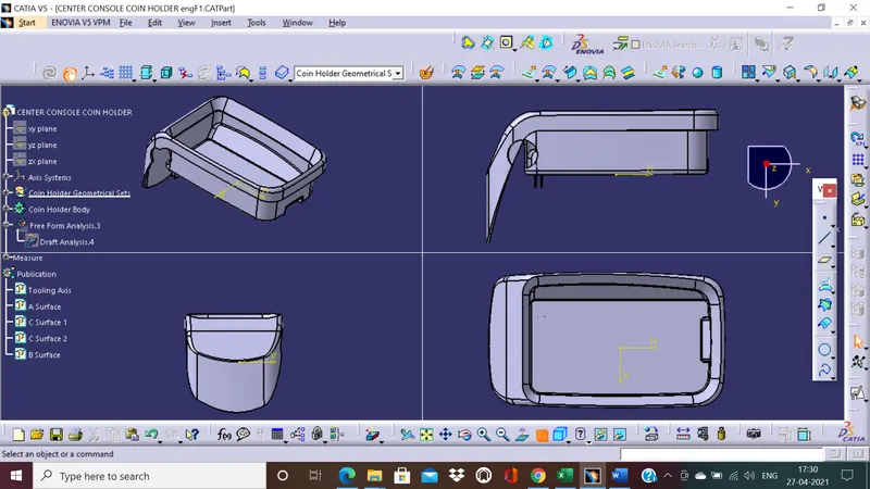
Q1:Right Side view
Q2:Isometric view
Q3:Back view
Q4:Bottom view
Please see the cat part in the zipped file. Thank you.