Week 9 - Attachment Feature Creation - Challenge 1
Attachment Feature Creation- Rib Design
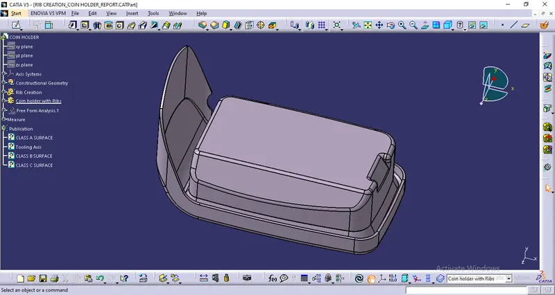
Create the rib for the Centre console coin holder considering the design rules.
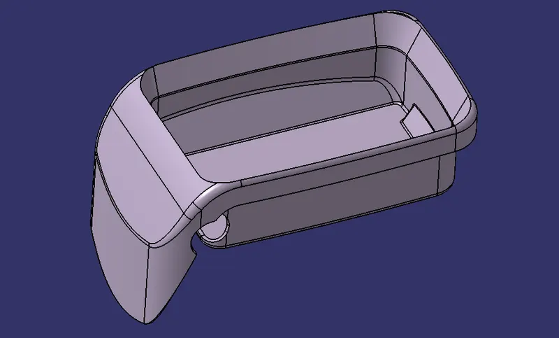
Under standing Rib
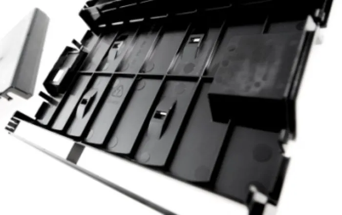
Ribs are thin wall protrusions that extend perpendicularly from a wall or plane. They are usually found in clusters offering support to a plane that would have otherwise been too thick, but can also be a stand-alone support for a single wall. Ribs are an important part of product design and will ensure that the product will remain both strong and flexible to desired specifications.
Designers commonly try to increase the strength of a part by making its walls thicker. Unfortunately, walls that are too thick are subject to warpage, sinking, and other defects. The advantage of using ribs is that they increase the strength of a part without increasing the thickness of its walls. Because less material is required, ribs can be a much more cost-effective solution as well.
Creating the rib for the Centre console coin holder using CATIA v5
Guidelines
1. Rib Design
Measure the thickness of the base surface for rib-
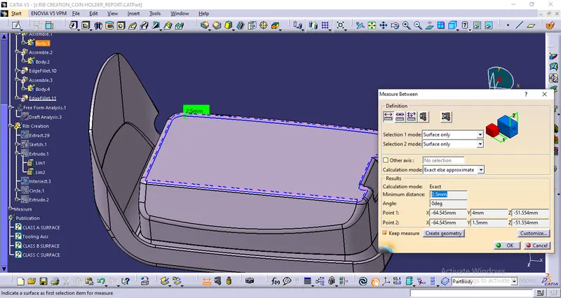
- This thickness value 2.5 mm will be required in upcoming stages.
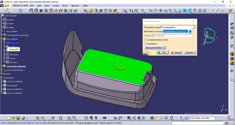
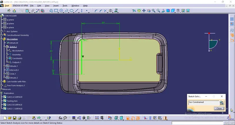
Extract the Back surface on which the rib will be created and create a sketch for the rib.
Extrude rib surface-
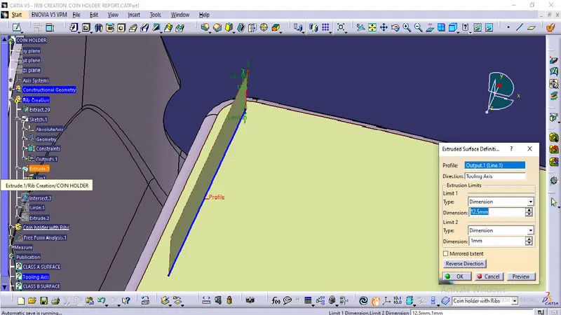
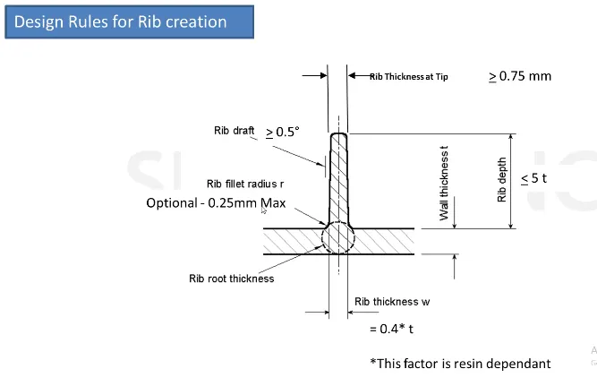
- Height of the rib 'H' should be less than or equal to 5 times thickness.
- H = 5 x 2.5 = 12.5 mm
Thicken the rib surface-
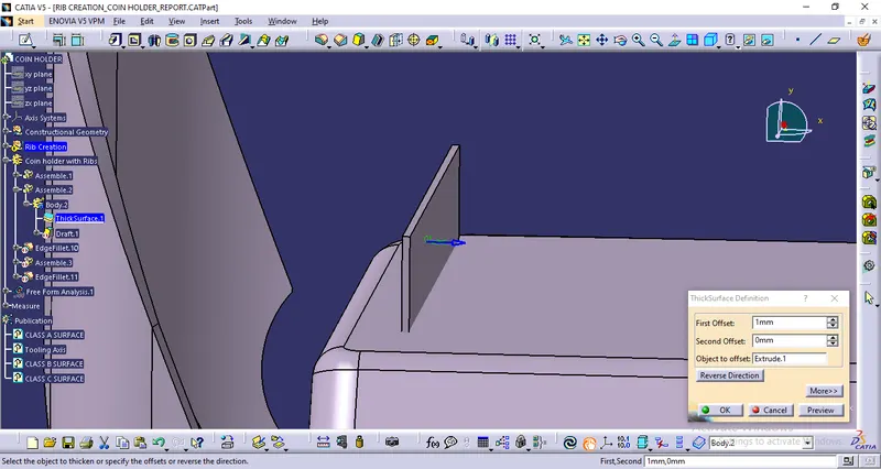
- Thickness of rib 'w' sould be 40% of the wall thickness.
- w = 0.4 x 2.5 = 1 mm
Provide Draft on each side of rib-
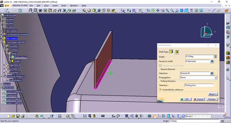
- Minimum 0.5 degree of draft should be there for the rib.
Check the thicness at the tip of the Rib-
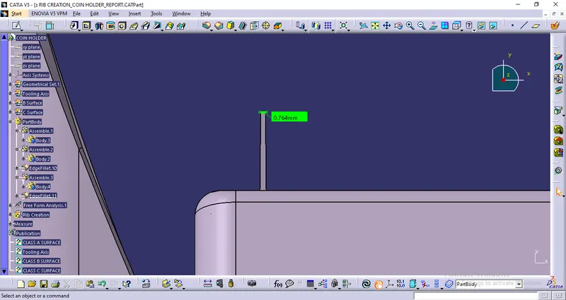
- Thickness at the tip of the rib should be atleast 0.75 mm and here it is 0.764 mm
Give fillet-
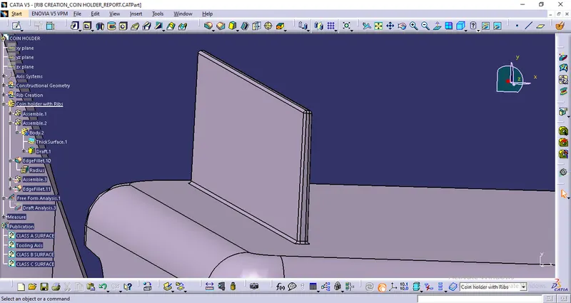
- Genereally fillet radius should be 0.125 times thickness
- But the maximum fillet radius can be 0.25 mm.
Create circle at intersection to check rib root thickness.
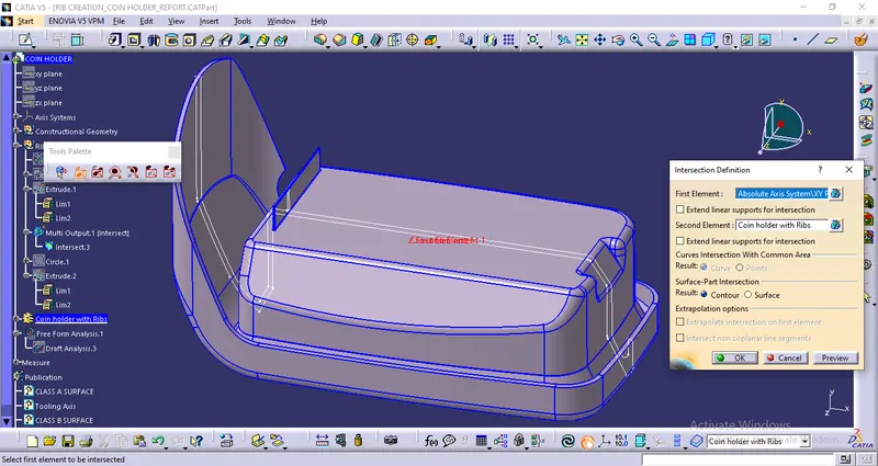
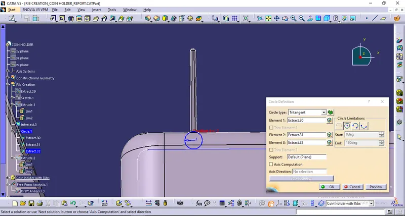
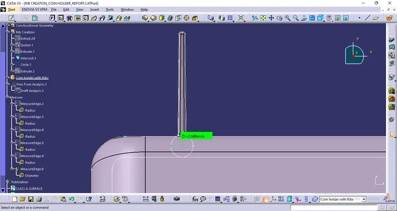
- Rib root thickness should be between ±30% of the wall thickness.
- D = 2.686 mm satisfies the condition.
Similarly create one more rib with standard spacing-
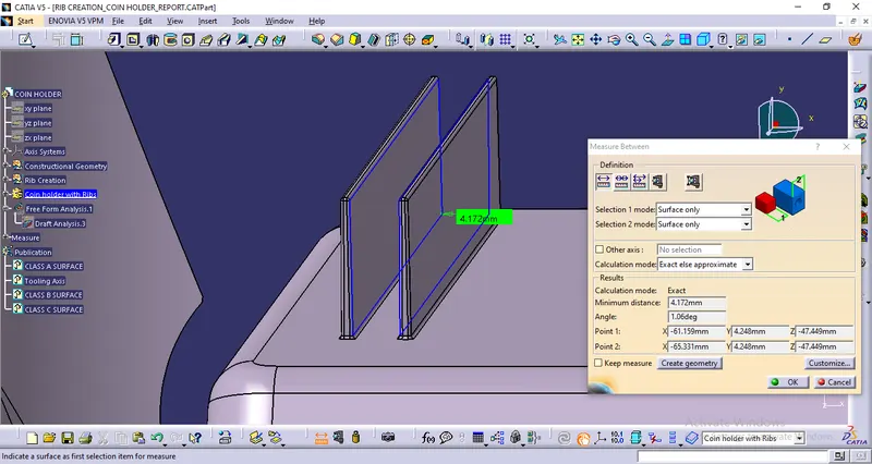
- Height to gap ratio for ribs is 3:1
- Gap = H / 3 = 12.5 / 3 = 4.17 mm
Similarly following these principles as many ribs can create as required.
2. Draft Analysis
Analyse the ribs at 0.5 degree draft-
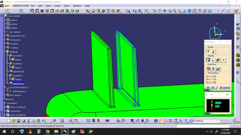
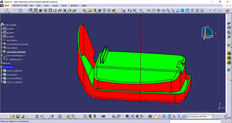
As the ribs lies in green zone in the draft analysis which suggests that all faces have minimum 0.5 degree draft angle, which makes the part manufacturable.