Week 9 - Attachment Feature Creation - Challenge 1
AIM:
To create a coin holder with ribs from the given A surface by adding a thickness of 2.5 mm to it and to create ribs as per the design standards .
PROCEDURE:
1)Tooling axis
Tooling axis is nothing but the duirection in which the core and cavity opens and closes . Design engineer works is to analyse the class A surface and find out the besy possible tooling direction keeping in mind all the draft angle is with respect to the tooling axis so that the component can be easily ejected from the moulds.
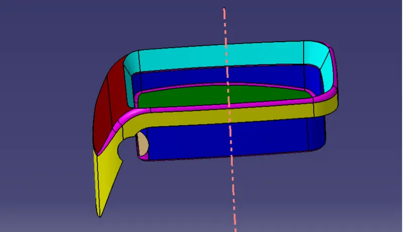
2)A Class surface
In automative design,a class A surface is any of aset of freedom surface of high efficiency and quality.Although,strictly ,it is nothing more than saying the surfaces have curvature and tangemcy alignment- to idealaesthetical reflection quality.Many people interpret class A surface to have G2(or even G3) curvature continuity to one another.Class A surfacing is done using computer_aided industrial design applications.Class A surface modellers are also called" digital sculptors" in the industry. Industrial develop their design stylling through the A- surface,the physical surface the end user can feel,touch ,see etc.
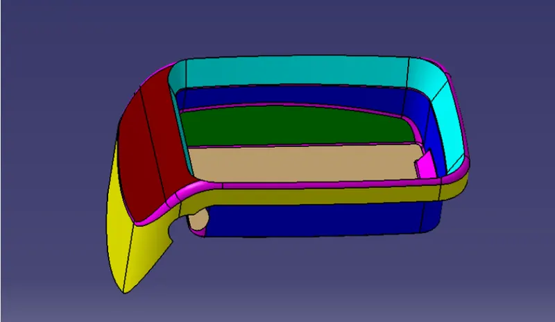
3)B Class surface creation
Represent internal and functional surfaces.This cluster exemplary includes derived surfaces created by offset operation from class A surfaces to define the thickness of material.In this file important to link class B surfaces geometrical to enable an adaptation to class A surfaces automatically in case of styling change.
After creating the tooling axis,B surface is to created which is nothing but the surface parallel to the A surface .B surface contains all the fillets and the edge which the A surface contains.
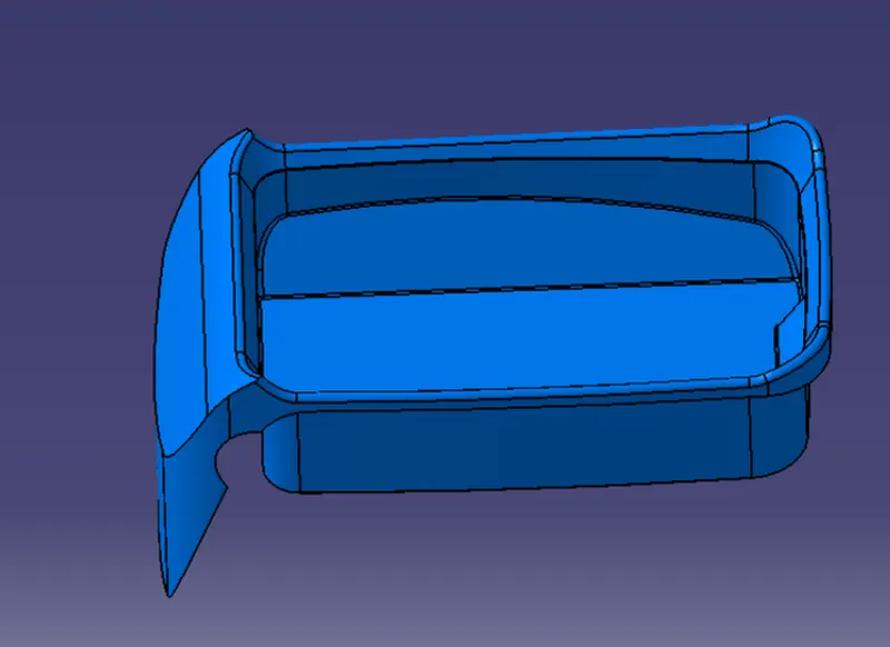
4)C Class surface creation
Class C surafce is swept along the boundary of the class A at an angke perpendicular to the class A surface with respect to the tooling axis direction with a draft angle of 3degree.
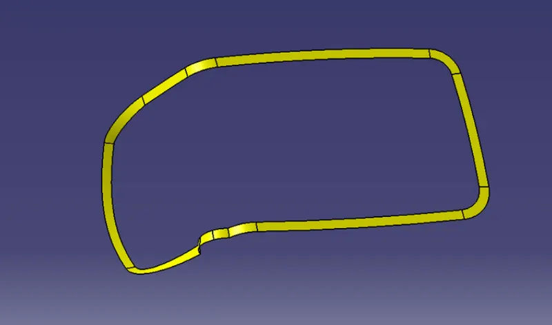
5) Joining Class A,B and C surface to get a closed surface
After finishing all the 3 surfaces,join the class A and class C surfcae together using the join command .Now, the joined surfaces are then trimmed with class B surface to form a closed surface.
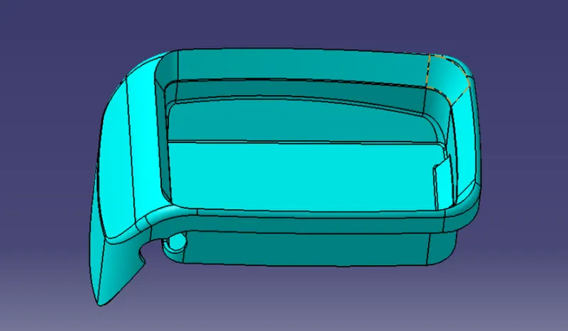
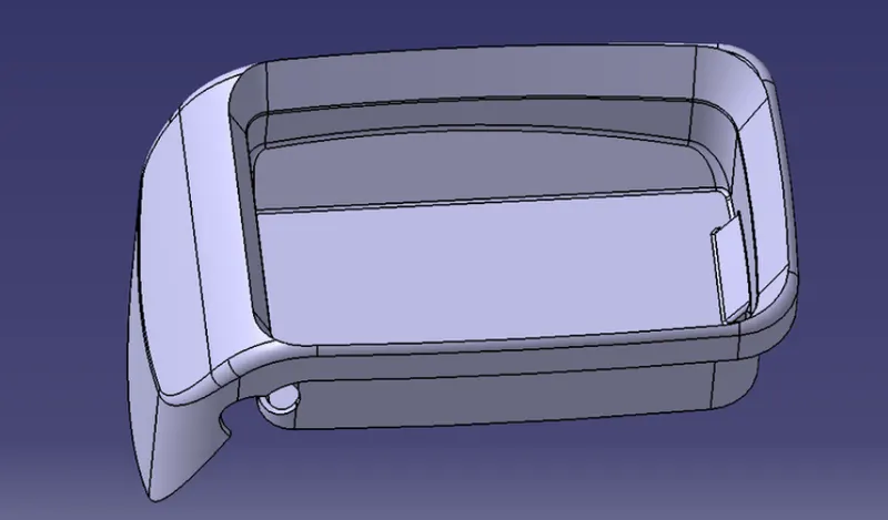
6) Draft analysis
The Draft analysis command enables you to detect if the part you drafted will be easily removed. This type of analysis is performed based on colour ranges identifying zones on the analyzed element where the deviation from the draft direction at any point, corresponds to specified values.
Draft angles are very important in thermofoming product design.If the product is formed onto a female or negative mould,it shrinks away from the mold sidewalls .As a result ,true femaleor negative products can be with vertical thermoformed with vertical walls having zero draft angles.
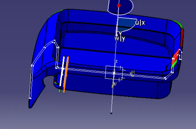
7) Creating ribs
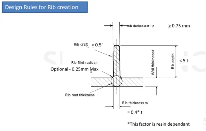
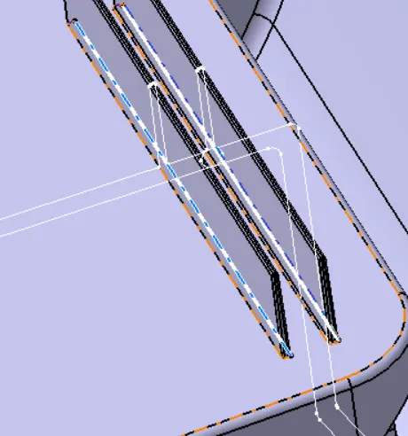
Create the ribs as per the design rules and give the required draft angle.Ribs are created to increase the stiffness and strength of the surface.
Result:
- Class A,B and C surface was created as per the automative standards using catia V5 Software.
- Draft analysis was performed for the built model and it could seen that the draft was under possible limit for the manufacturing of the component.
- Ribs were created for the component as per the design rules.