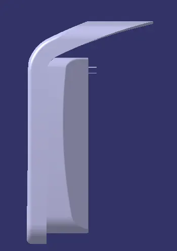
Week 9 - Attachment Feature Creation - Challenge 1
DEAILED REPORT ON COIN HOLDER DESIGN WITH RIBS
In this model of Coin Holder Design the following sections are we are going to do both practical and theoritical.
- Tooling Axis Creation
- Draft Analysis Report
- Design of Ribs
Tooling Axis Creation
To create a Tooling axis , start analys the model which section looking good to clear all the faces. One of type of creating a tooling axis by intersection method of xz and yz plane and using Bisecting method we have an mean line for the toooling axis.
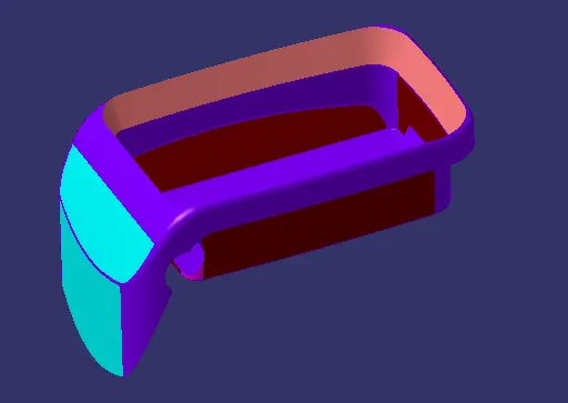
Intersection of YZ plane
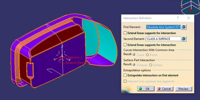
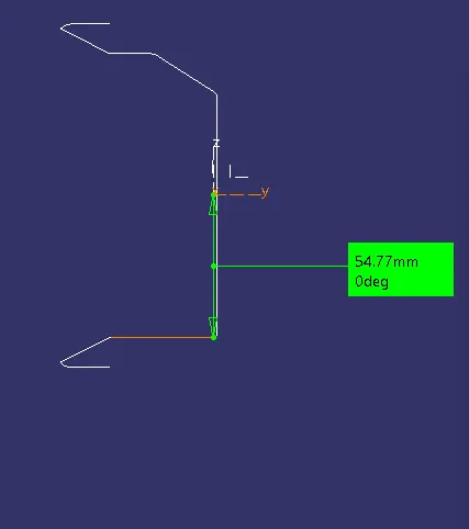
In the YZ plane intersection we come to know there was no draft angle given in one sided of the wall it looks staright 90 degre side. In Mouldibd parts parts without draft angle will look difficult for ejecting an component from the moulding. Hence, its a Class A component we cant do any changes here. We go according to the Class A model. Bisecting method will not come to act in this model, since we have taken the center point line of base as an tooling axis.
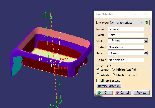
Lets create an point in the flat surface of the model , make the surface as a exracted surface, use the feature as point on surface give distance has an 0mm for the center point of the surface. From there draw an line with normal to surface and make them as tooling axis line for the Coin Holder Part.
Draft Analysis for Class A
Do an draft analysis report on the givn class A surface, lets see how it works ithe compnent.
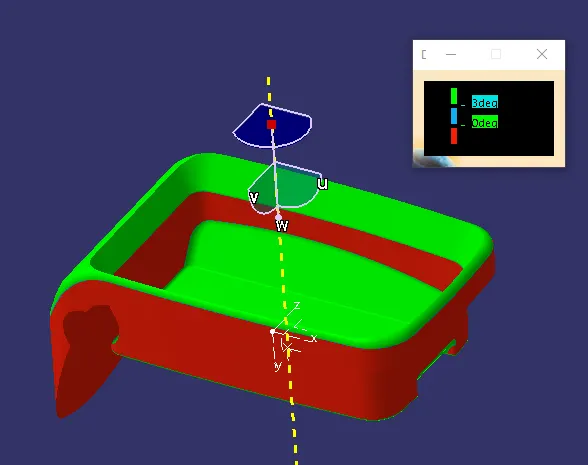
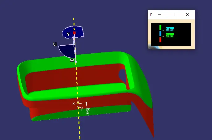
So, after applying the draft analysis as we know two face of wall was not in specified draft angle. Hence the wall sided faces are not cleared they are below 0 degree.
DESIGNS OF RIBS
Importance if rib design in a model
- The design of ribs leads to the economical stiffness and strength in moulded parts without increasing the overall wall thickness.
- Loate and arrest the components of assembly.
- Providing alignments in mating parts.
- Acting as stops or guides for mechanism( For eg : Use to tilt the Head lamp).
Guidelines to design a Rib on Show surface
In the Coin holder part we design the ribs in the outer portion of the part, so we have to follow some guidelines to ensure the designed rib is safe and avoid plastic defects while manfacturing the part.
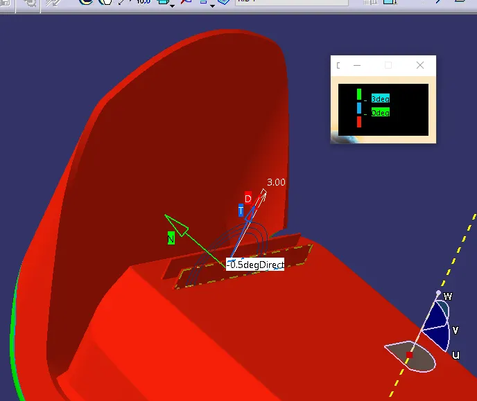
- Draft angle: The minimum draft angle used per side is 0.5 degree.
- Wall thickness: The wall thickness of Rib can be calculated by multiples of 0.4mm to the thickness of base part 0.4*T
- Height: The height of the rib can be calculated by the multiples of 5 with the base height of the part 5T.
- Spacing ( In case of two ribs): In the case of designing two ribs the space value should be given by 3:1 ratio of the component. Height/width<3.
- Thickness at tip of the Rib: The thickness of the rib tip has to be minimum value of 0.75mm. Cant be lower than this because in thinner rib flow of plastic will not flow normal. It will create the plastic defects.
- Optimal radius: The minimum optimal radius of the rib is 0.125*T.
Ribs in Coin Holder
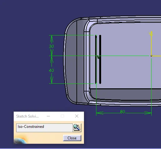
- Extract the base and create an positoned sketch with xz plane projection point as a tooling axis point.
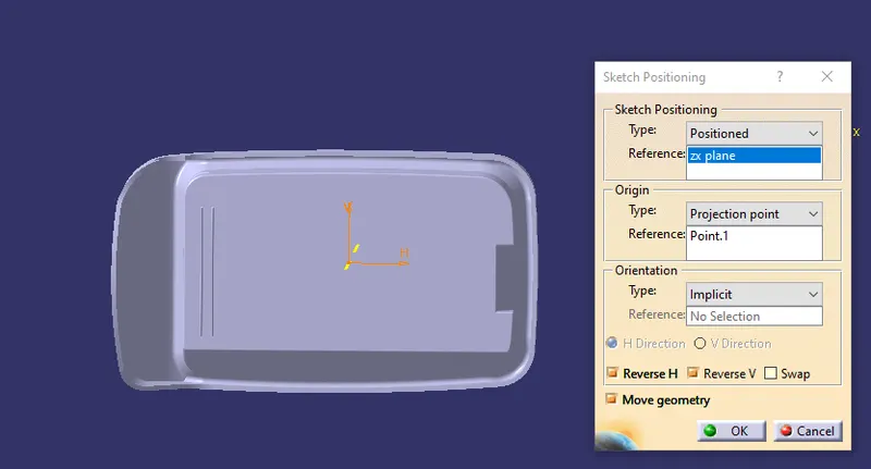
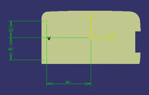
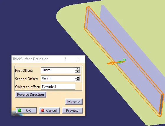
- Extrude the line and apply thickness feature, value must be given to rules of rib design structure.
The extruded value will be calculated by 5T. The thickness of the part is 2.5mm and the extrude value will be 5*2.5= 12.5mm. Make sure the lower portion of the rib closes to the part , adjust the lower value according to that.
- The Wall thickness of the rib is calculated by 0.4*T = 0.4*2.5 = 1mm. Add the body to the main body of the coin holder part.
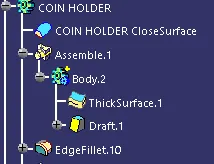
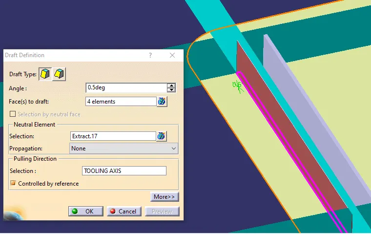
- Next apply the draft angle to the rib. The minimum draft angle for the rib is 0.5 degree. Selelct all the four sided face with neutral element has extract base and pulling direction be the tooling axis.
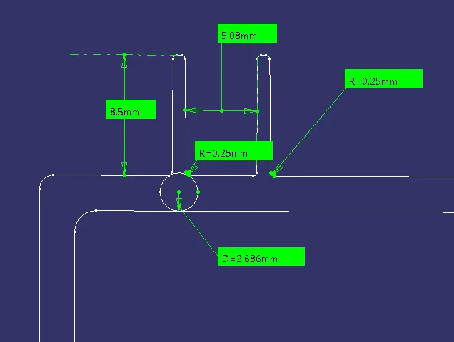
- Fillet radius to the drafted rib should be calculated by 0.125*T, 0.125*2.5= 0.3125mm. The minimum radius value is 0.25mm, so we can go with 0.25mm.
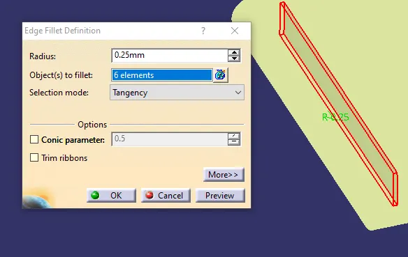
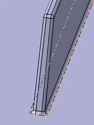
Rib Root thickness
The rib root thickness is calculated by creating a tritangent circle of the rib fillet radius and the base of the part model. To understand clearly, use intersection of Coin holder part with a plane XY.
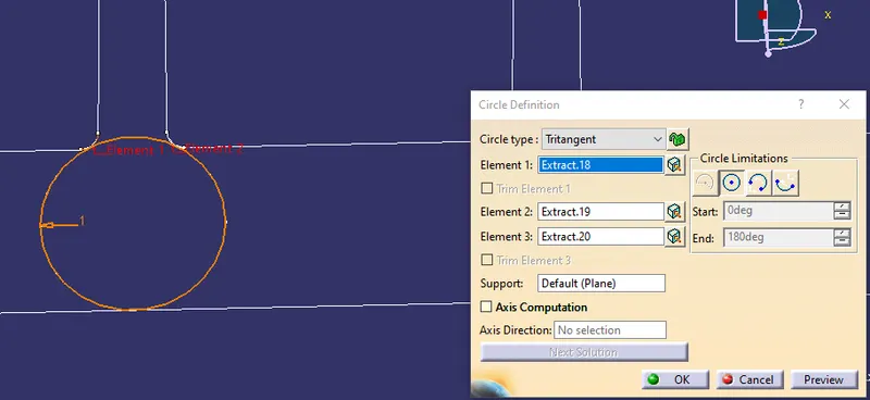 .
.
The rib is designed lets check the measurements in the intersection mode, whether the values are in specified dimensions.
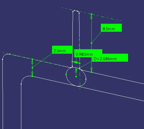
RIB 2
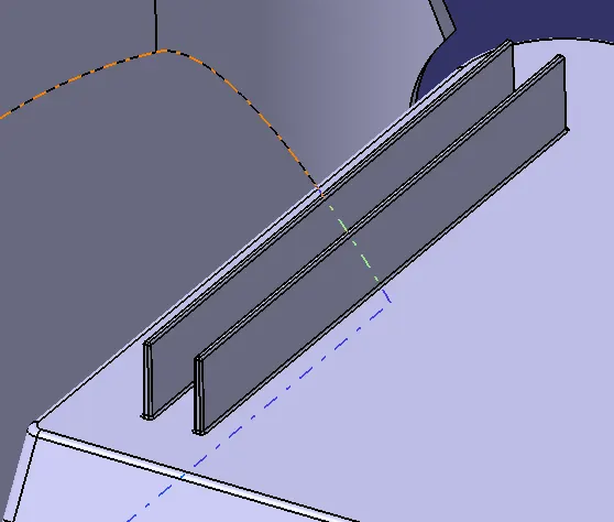
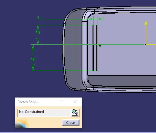
The other side of Rib designed in same manner but need to ensure the space between the ribs according to the rib design rule.
- The space vale can be calculated by the height/width raio.
- Ratio of 3:1 is allowed, prefered value of ratio is 2:1.
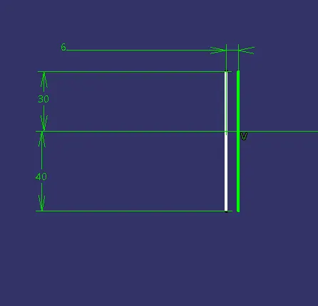
For the Coin holder rib it can be calculated by Height(T)= 12.5mm / widtth < 3.
- 12.5/W=3; w= 12.5/4 = 4.1mm. For safer side we can keep it it as 5mm. Because we have to add the thickness of the rib to the width space. 5+1=6mm.
DRAFT ANALYSIS ON PART MODEL
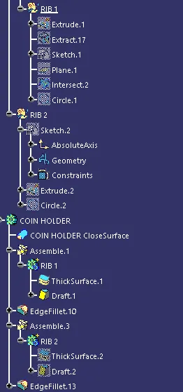
GEOMETRICAL SETS
SKETCH SOLVING STATUS
DRAFT ANALYSIS ON PART MODEL
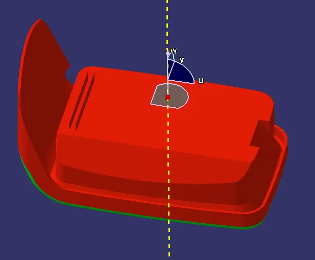
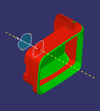
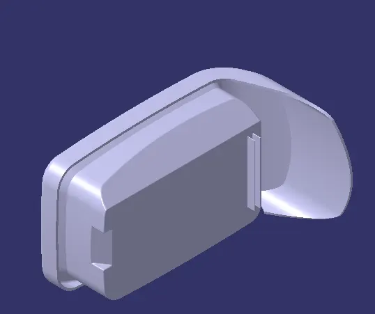
Apply draft analysis to the part model check the drafted angle of faces created between Class Aand Class C. As we already discussed in the Class A draft analysis model the side walls of the class A as no drafted faces. We have created the ribs and check the draft analysis for that.
DIFFERENTIAL VIEWS OF MODEL
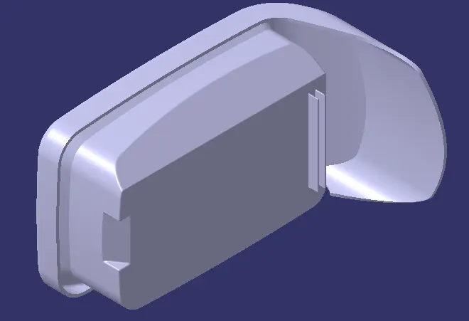
ISOMETRIC VIEW
FRONT VIEW
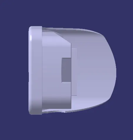
SIDE VIEW
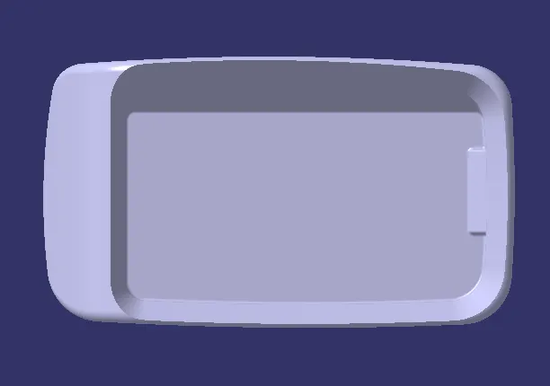
TOP VIEW