Week 10- Assembly Workbench
ASSEMBLY WORKBENCH
In Assembly workbench we are going to see about two assembly parts. They are as follows
- QUICK RETURN MECHANISM
- CV-JOINT
QUICK RETURN MECHANISM
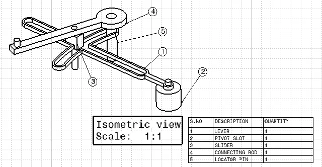
The Quick Return Mechanism can be assembled by using five diiferent parts. They are as follows
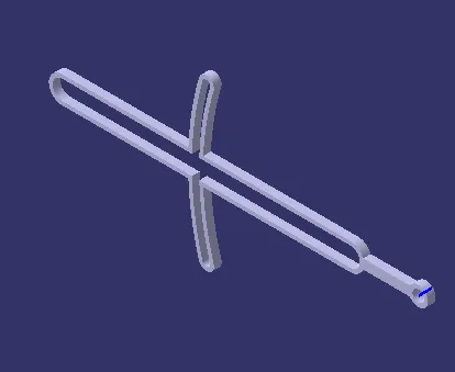
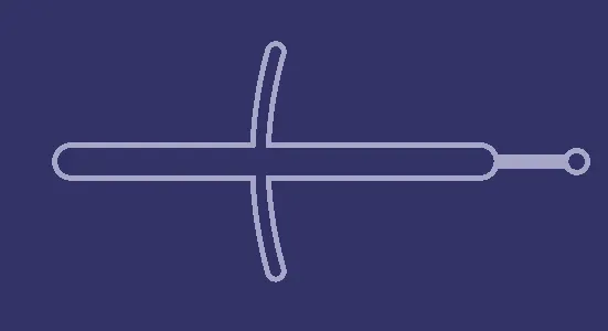
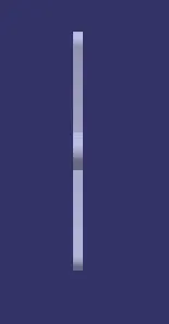
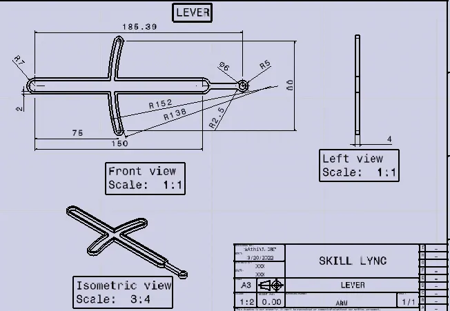
- LEVER
- PIVOT SLOT
- SLIDER
- CONNECTING ROD
- LOCATOR PIN
We are going to design the assembly parts in both 3d and 2d drawings.
- LEVER PART
SKETCH SOLVING STATUS
3-D MODEL DESIGN
2D- DRAWING
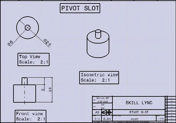
*PIVOT SLOT
SKETCH SOLVING STATUS
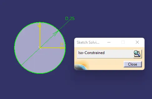
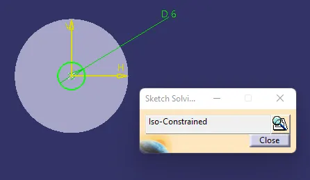
3-D MODEL DESIGN
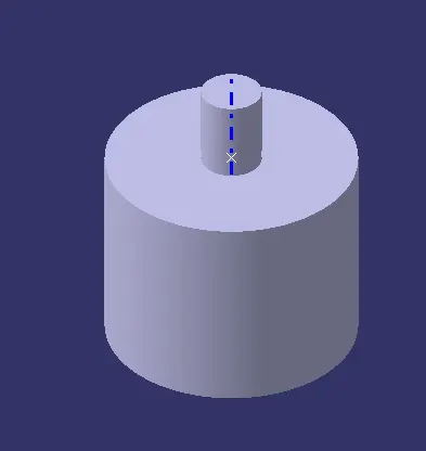
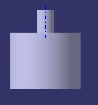
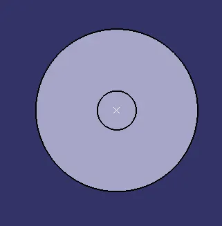
2-D DRAWING
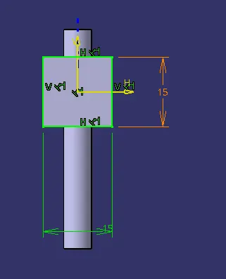
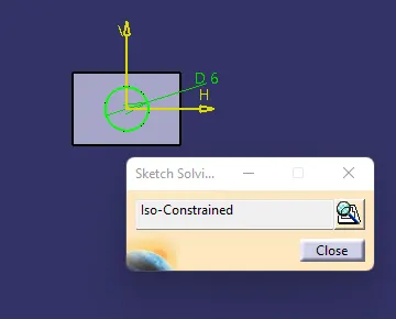
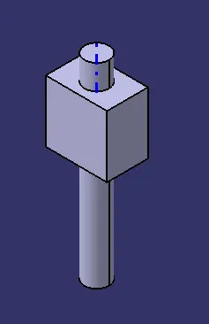
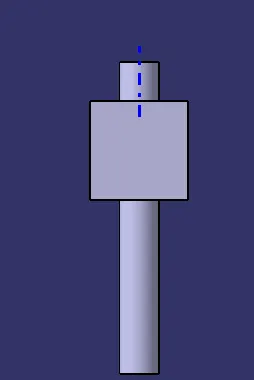
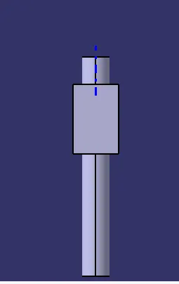
SLIDER
SKETCH SOLVING STATUS
3-D PART MODEL
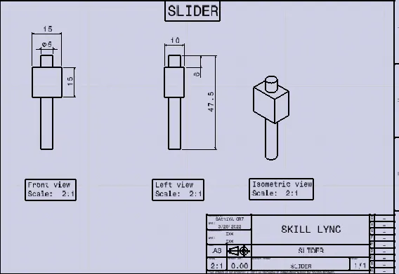
2-D DRAWING
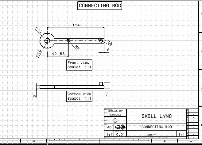
*CONNECTING ROD
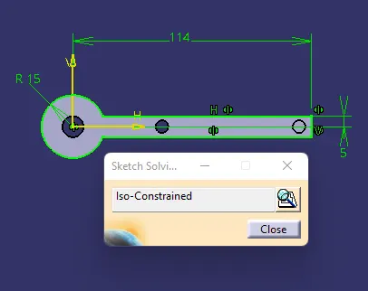
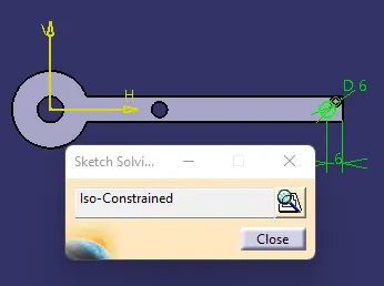
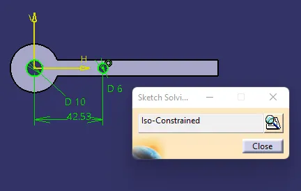
SKETCH SOLVING STATUS
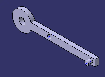
3-D PART MODEL
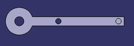
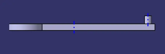
2-D DRAWING
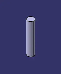
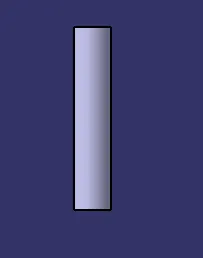
*LOCATOR PIN
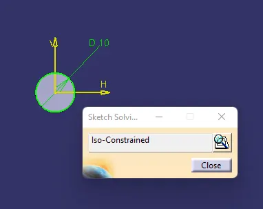
SKETCH SOLVING STATUS
3-D PART MODEL
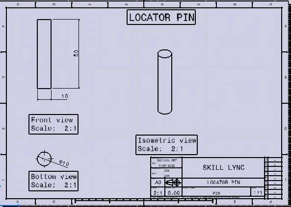
2-D DRAWING
REPORT ON FINAL ASSEMBLY
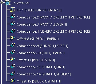
- To perform a assembly part, we need a reference point to fix the part model to the reference point it can be named as skeleton reference.
- Create a new part and project the point in coodirantes with 0mm distance.
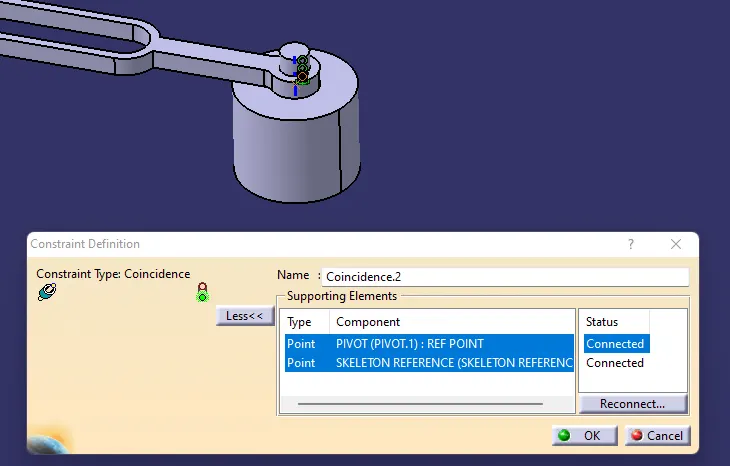
- Coincidence the Skeleton reference point to the Pivot part reference point, because its a non movable part in the mechanism.
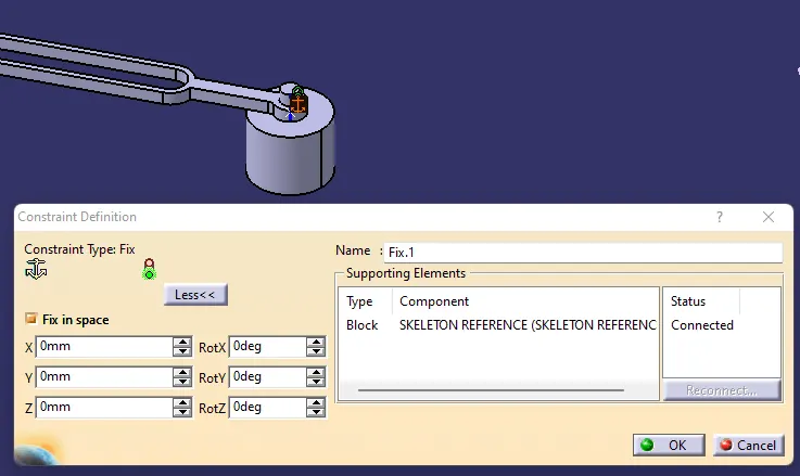
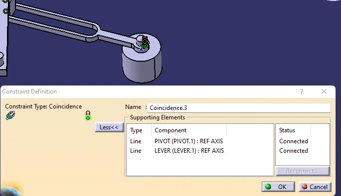
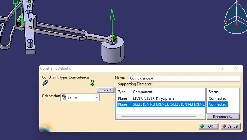
- Next up coincidence the lever arm reference axis to the Pivot reference axis . Then constraint the xy plane of both lever arm and pivot slot to assemble them both as fully constrained.
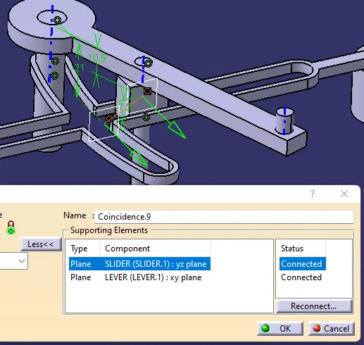
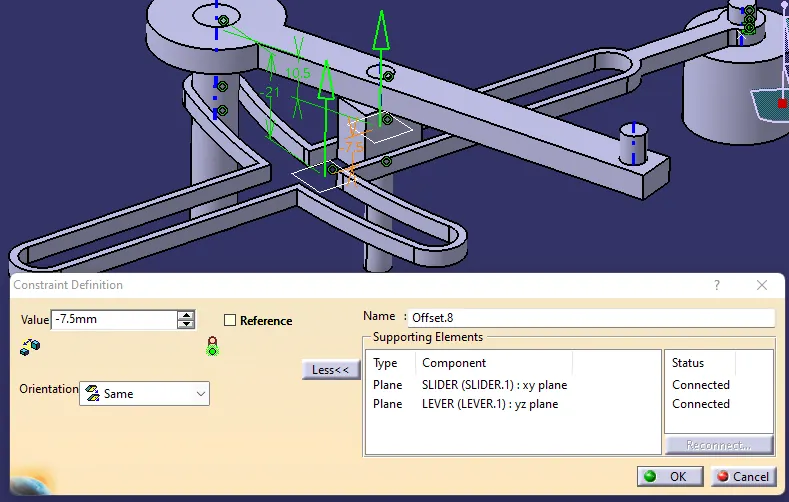
- Assembling Slider with Lever Arm. Coincidence the yz plane of slideer to the xy plane of lever arm to move the slider only in respective direction. Offset constrain the xy plane of slider with yz plane of lever arm to match the bottom face of lever arm and slider in parallel.
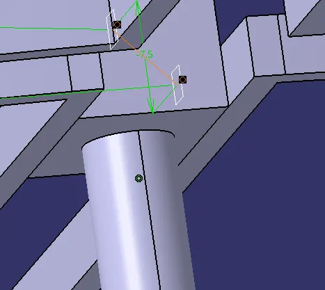
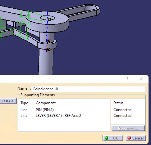
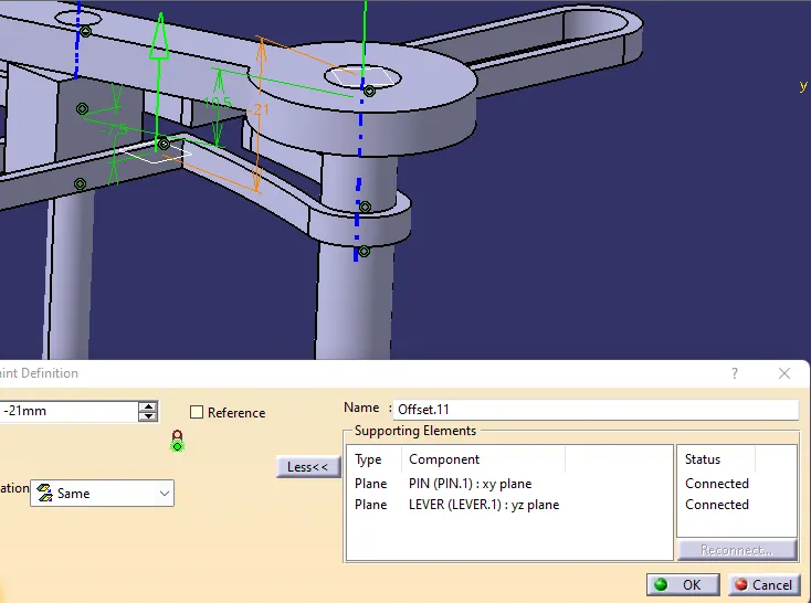
- Constrained the pin to the one side of the lever arm, it as been a supporter for a connecting rod of the mechanism. Coincidenc the reference axis of lever arm to the reference axis of an locator pin. Then using offset constrain coincidence the locator pin to the lever arm with the repective offset distance requiered.
- Assembly of an connecting rod is to coincidence with two part one is with locator pin and other with the slider. Coincidence both the reference axis with locator pin and slider part. Next using offset constraine offset the center hole of the connecting rod with the slider. To activate the movement of the connecting rod.
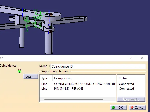
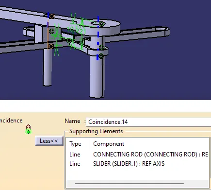
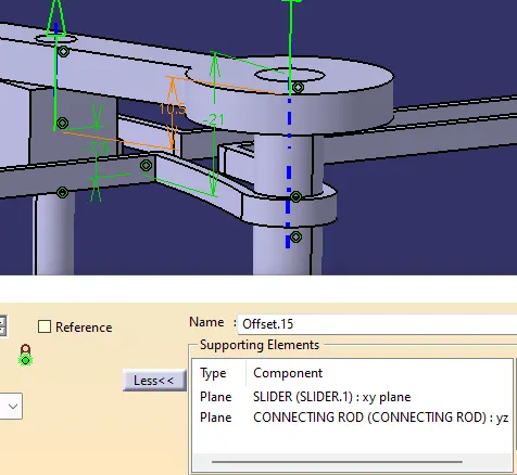
FINAL ASSEMBLY
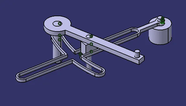
CONSTRAINTS
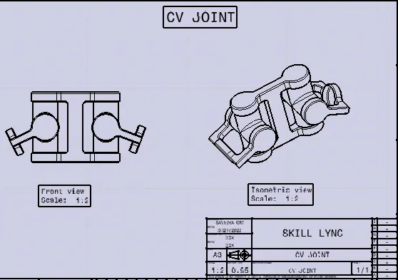
2-D DRAWING
Application of Quick Reurn Mechanism
It is used in the shaper machine to flatten the workpiece. Slotter and Planer are used the same in machines. It is also used in screw presses, mechanical actuators, and rotary combustion internal engines.
CV-JOINT
The assembly of CV-JOINT is of three parts
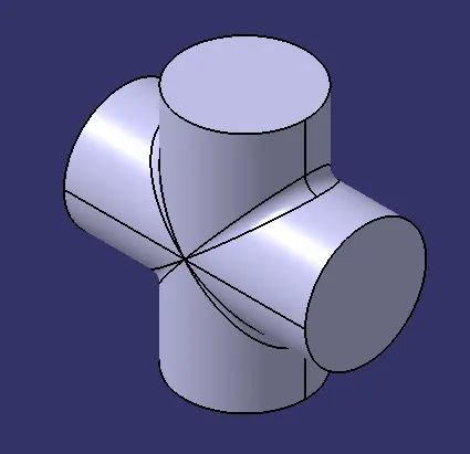
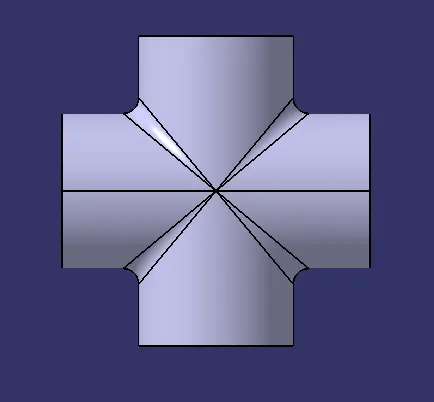
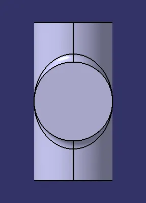
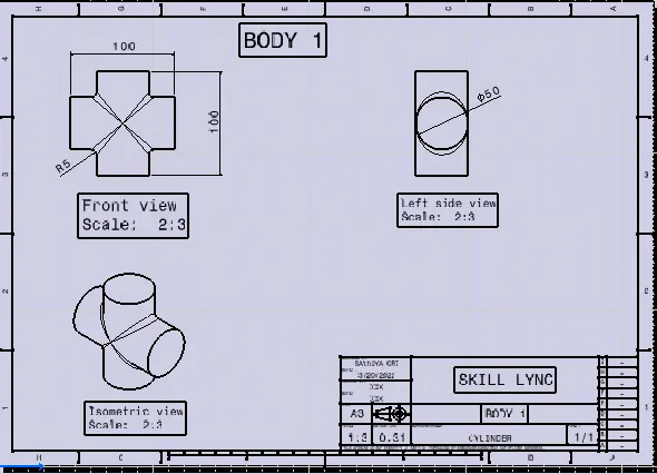
BODY 1
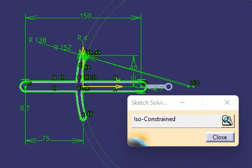
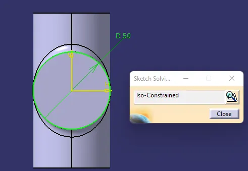
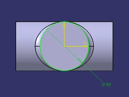
SKETCH SOLVING STATUS
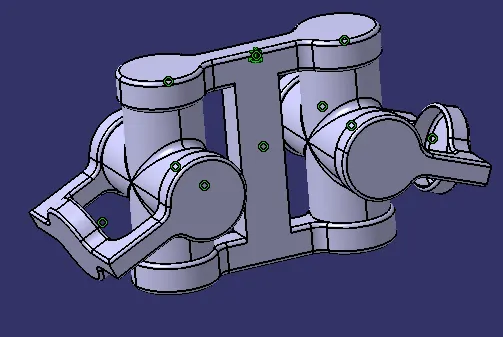
3-D MODEL
2-D DRAWING
BODY 2
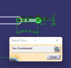
SKETCH SOLVING STATUS
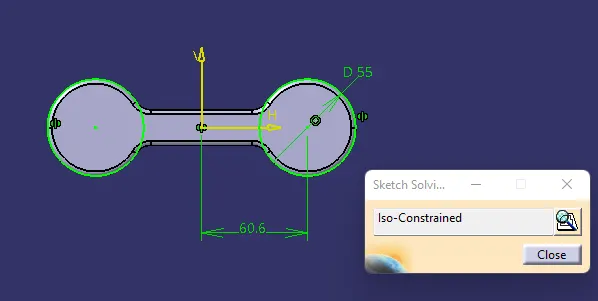
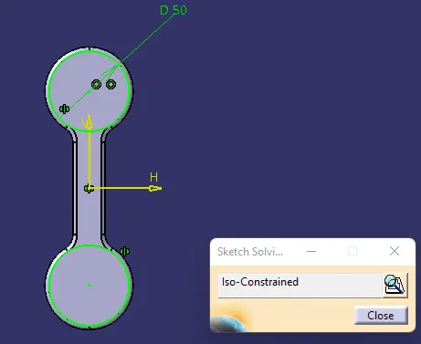
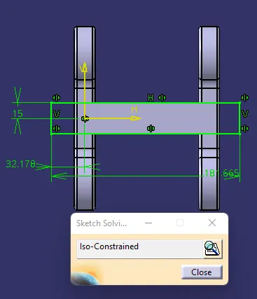
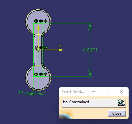
3-D PART MODEL
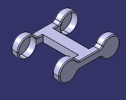
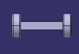
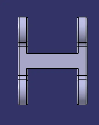
2-D DRAWING
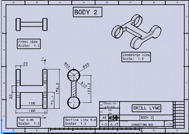
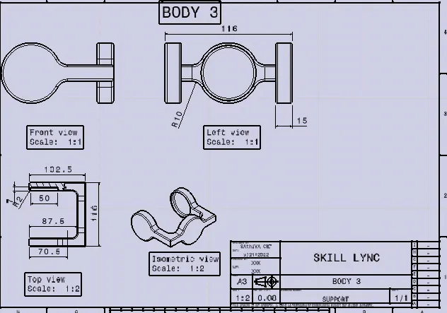
BODY 3
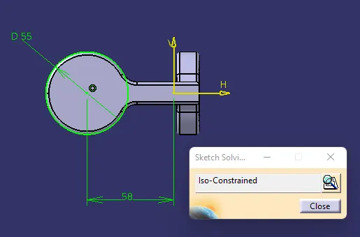
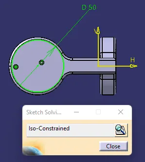
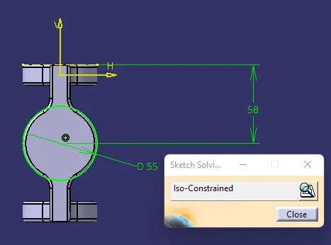
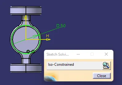
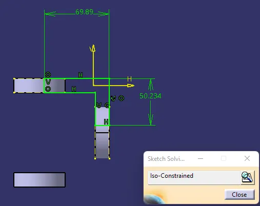
SKETCH SOLVING STATUS
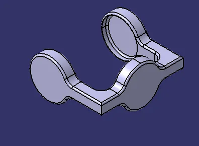
3-D MODEL
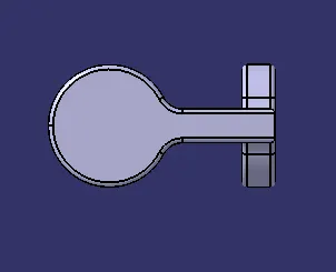
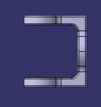
2-D DRAWING
ASSEMBLY OF CV-JOINT
- Create an reference point, name it as skeleton reference to fix the assembly in a common point.
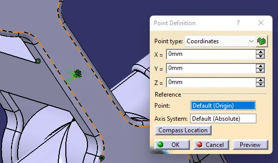
- Use the fix constrain to the skeleton reference, then coincidence the body 2 refernce point to the skeleton reference.
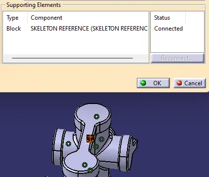
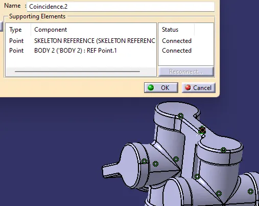
- Coincidence the body 1 reference axis of an hollow surface to the Reference axis of body 2. Coincidence the plane of xy plane of body 1 to the body 2 plane.
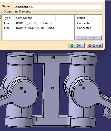
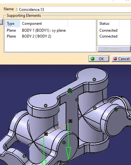
- Same steps has to be followed to the other side of the assembly part model.
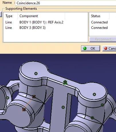
- Next assemble the body 3 to the body 1 by constrained horizantal ref axis of both body 1 and body 2. Then coincidence the center plane of body 3 to the body 1 plane to arrest the movements. Same as to be followed to the other side of the assembly part.
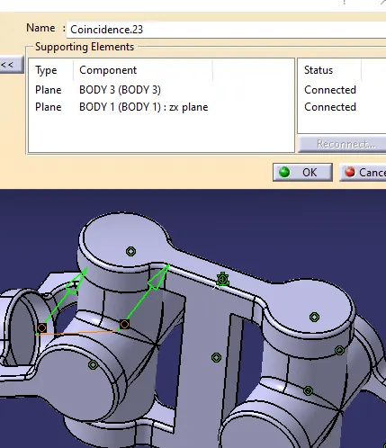
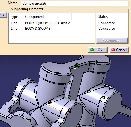
ASSEMBLY CONSTRAINTS
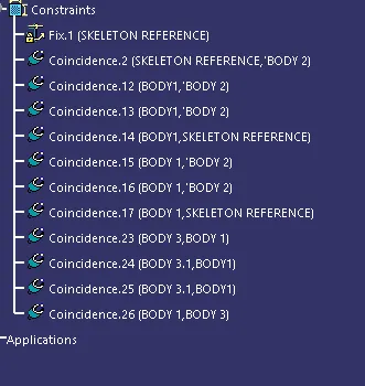
FINAL ASSEMBLY