Week 9 - Attachment Feature Creation - Challenge 1
RIB DESIGN
Objective: To create the Rib for the Centre Console Coin Holder considering the design rules.
Introduction:
Ribs:
Ribs are a feature in plastic injection molded parts. They are thin extensions that run perpendicular from a wall or plane. They are commonly used to provide additional support and strength to a part. The advantage of using ribs is that they increase the strength of a part without increasing the thickness of its wall.
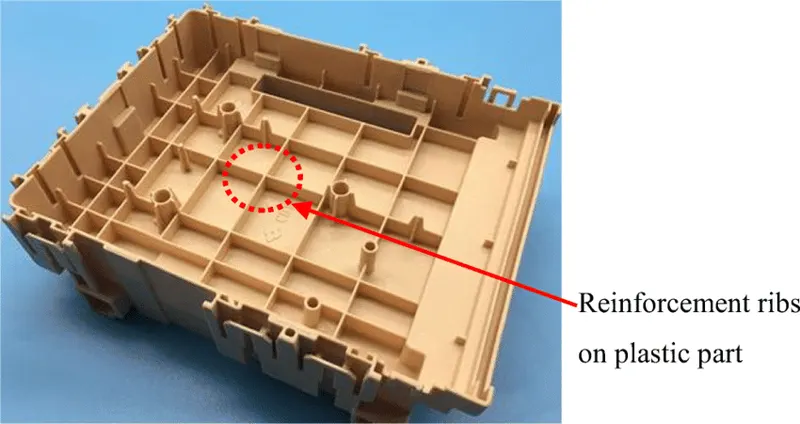
They also facilitate;
- Locating and arresting components of an assembly
- Providing alignment in mating parts
- Acting as stops or guides for mechanisms
General guidelines for creating ribs:
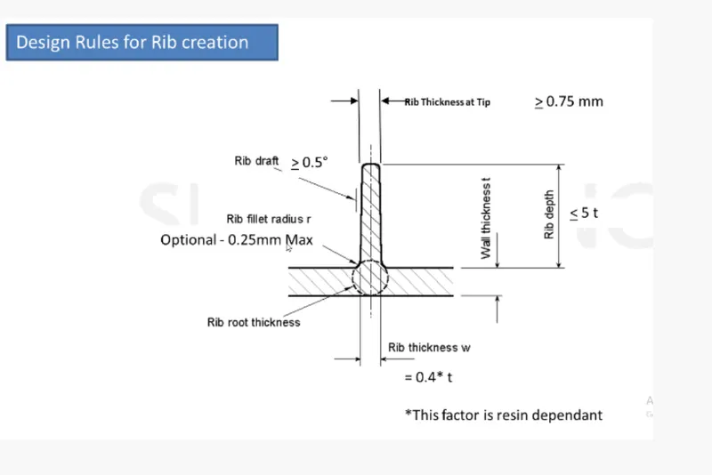
- Draft: Minimum of 0.5 degree per side which allow the rib to release from the mould.
- Rib thickness (w) should be 0.4*t (wall thickness).
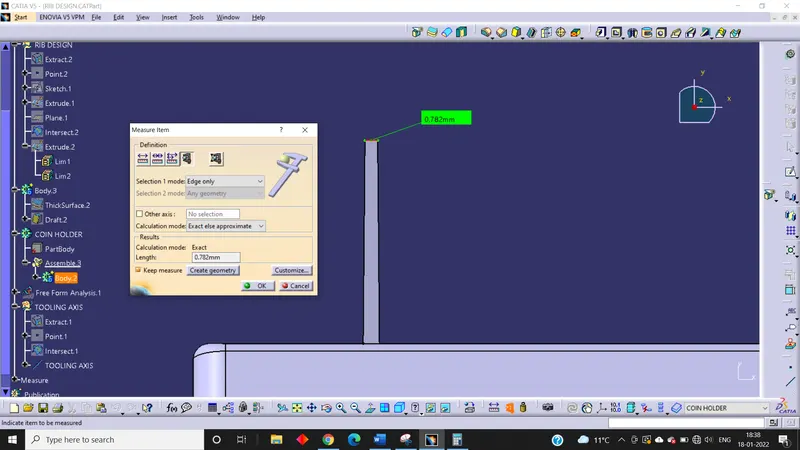
- Minimum thickness at Rib Tip should be 0.75 mm.
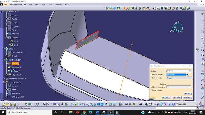
- Rib fillet radius: Optional fillet radius (r) is maximum 0.25 mm.
- Rib height/depth should be less than or equal to 5*t (nominal wall thickness).
- Ribs should be spaced so that the steel between the ribs is at a Height / Width ratio (3:1 steel & 2:1 preferred).
The ratio of height/width should be less than three.
Tooling Axis:
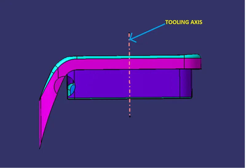
Tooling axis is the direction in which the mold or core and cavity opens.
Draft:
Draft is the angle in which the part is tapered to allow it to release. As the part cools, it tends to shrink to the core side of the mold. Draft is required on all parts in the direction of mold movement in order to allow parts to release or eject from the mold properly.
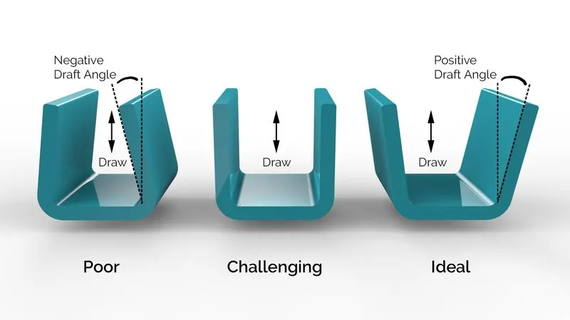
Most parts or applications require a minimum of 0.5 to 1 degree, however 3 degree is widely accepted as normal.
Procedure:
Creation of Tooling Axis:
Bisecting line method
First of all, we have to analyse manually or visually to see which direction is the most appropriate for tooling axis. After analysing we found that Z-direction seems easy to be tooled. So, we use the bisecting line method to create the tooling axis. For that we extract the base and create a point on the surface at 00 mm. After that we create an axis system on the same point and intersect the YZ plane with Coin Holder component. Here we found that the walls are at 0 degree to the normal which will be very difficult to manufacture as the plastic part would not eject at the end due to contraction after the cooling process is completed.
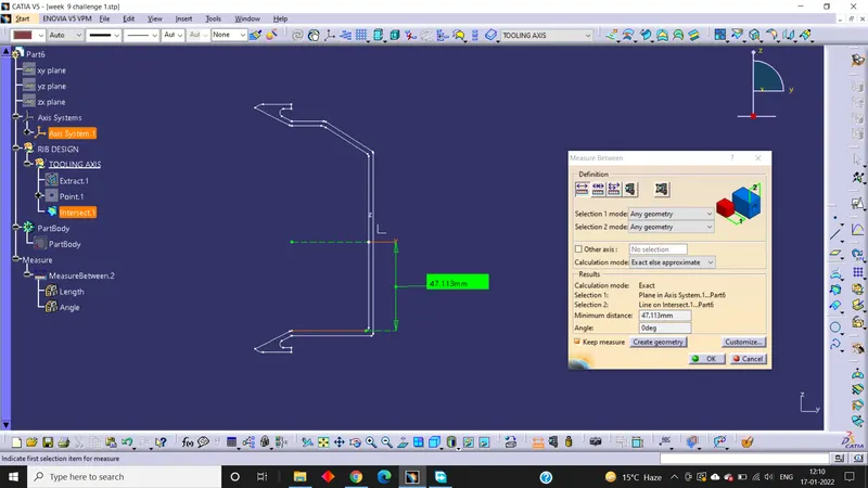
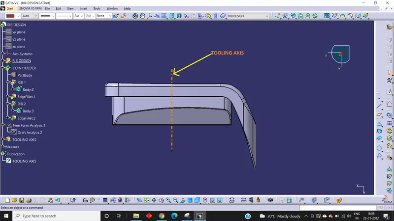
So, we have to contact with the styling team to give a minimum draft to the surface. But here, we will proceed with the same model. So, for that we create a line on a point that was created earlier using point and direction option giving the extract as a direction which means the line is normal to the surface. This is our main tooling axis.
Draft Analysis of the Coin Holder component:
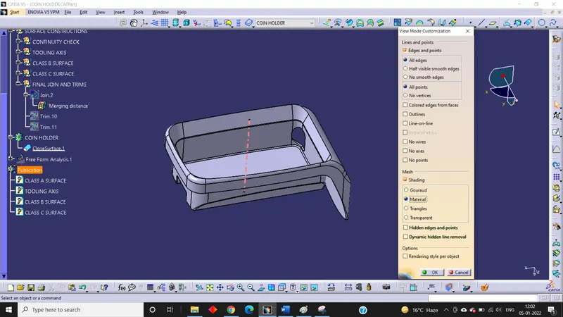
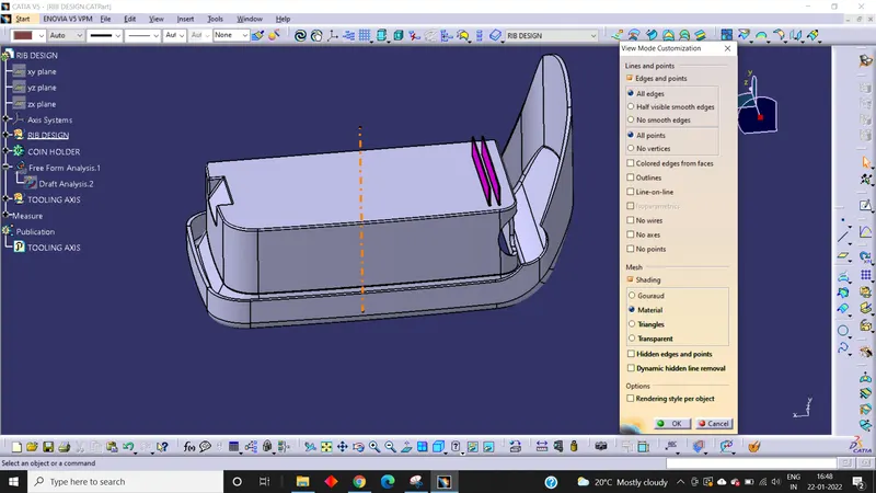
First of all, we should change the view to the Customize View parameters and then select the material mode and then Ok.
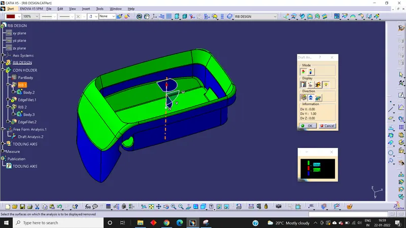
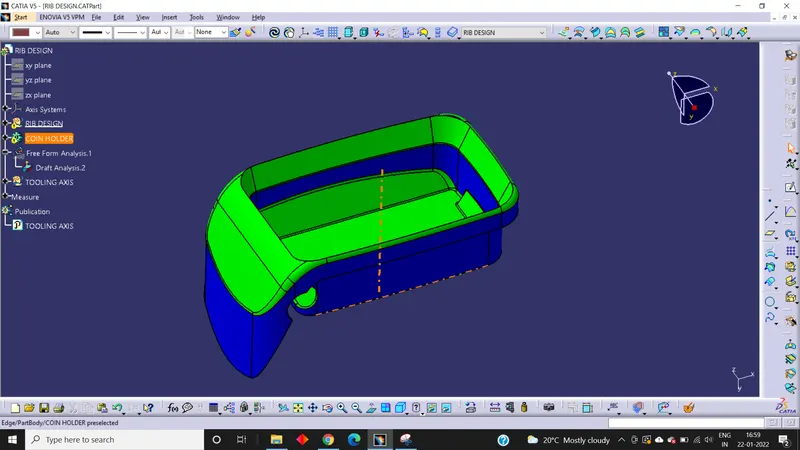
After that we will open draft analysis command and then click on the compass icon and then align the compass of the window with the tooling axis earlier created and then lock the draft direction. After that click on the surface and see that the surface is within permissible limit of the draft value. The surface should be green and in the column 3 degree should be inserted. But we found that the side wall and the outer flange are not clearing the draft in z direction as they are turned into blue. This is because the Class A Surface has not the minimum angles on the side walls and the outer flange.
Rib 1:
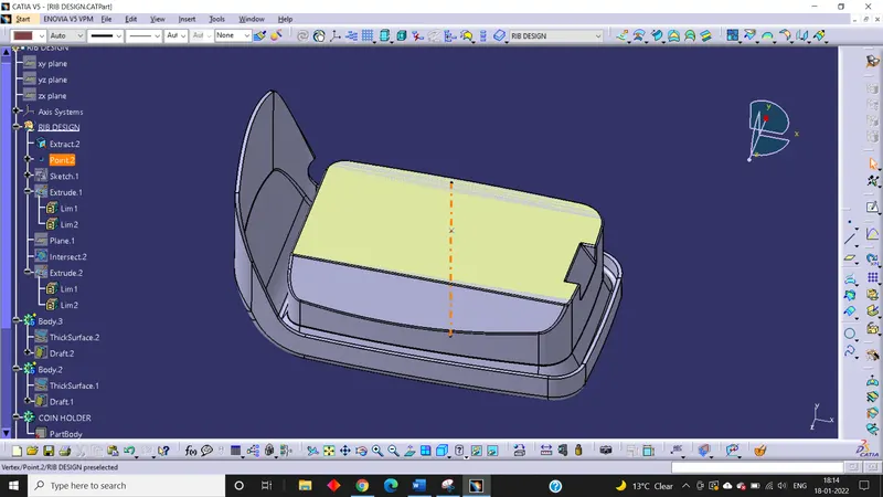
First of all, extract the surface on which the ribs will be created at then create a point on the surface.
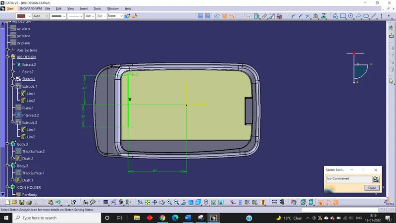
Now create a sketch for the rib 1 and change t output feature.
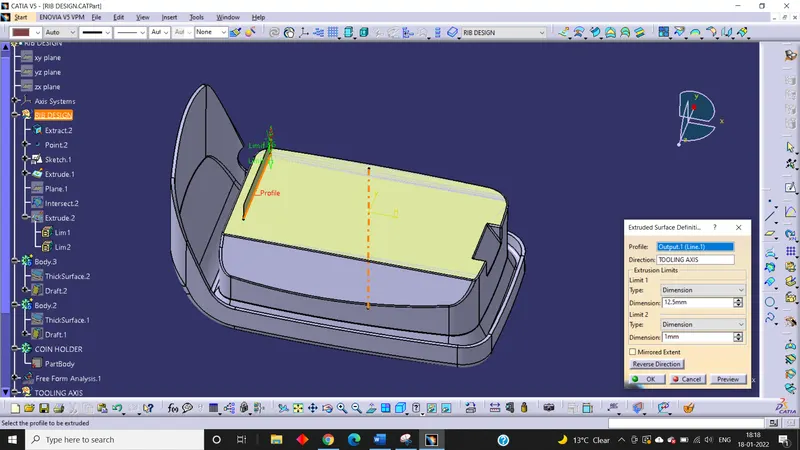
After that extrude the sketch considering the height of the rib i.e.
Height of the rib ≤ 5*t (wall thickness)
Here, the thickness of the component = 2.5 mm
So, the height = 5*2.5 = 12.5 mm
Now, we have to thicken the surface by switching into part workbench and using Thick Surface command. The thickness should be 0.4*t (wall thickness).
Here, wall thickness = 2.5 mm
So, rib thickness = 0.4*2.5 = 1 mm
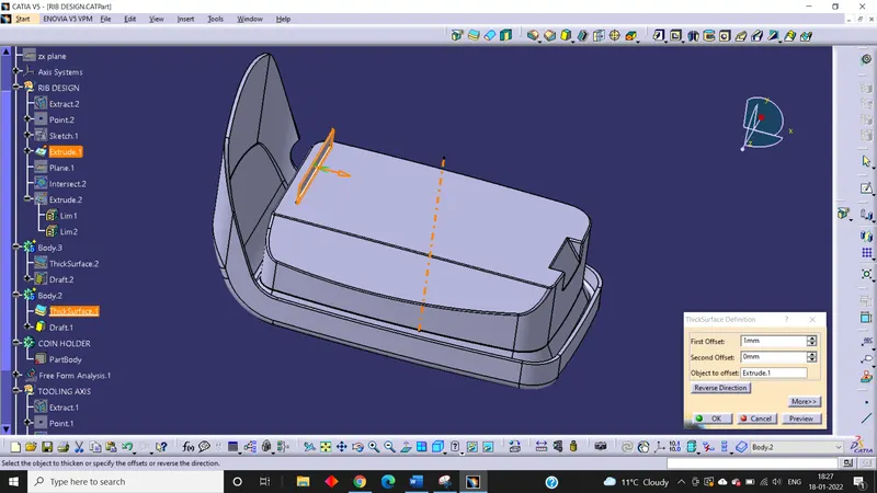
After that the draft of 0.5 degree should be provided on each side taking tooling axis as pooling direction.
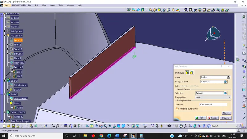
Here we have to maintain the rib thickness at the tip i.e. Rib thickness at tip ≥ 0.75 mm
Now this should be assembled to the main part of coin holder
After that the fillet should be applied at the edges.
Optional fillet radius = 0.25 mm
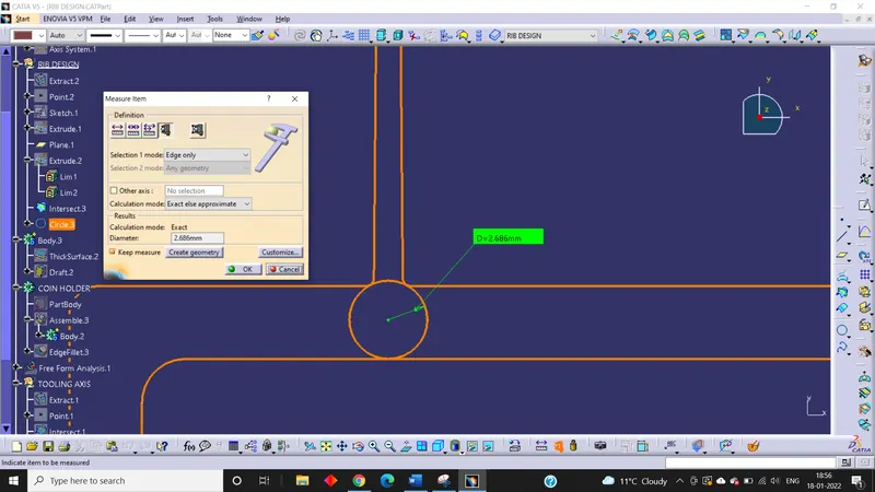
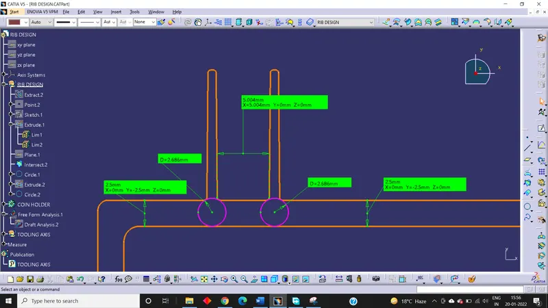
After that we check the Rib Root Thickness, for that first the component should be intersected using middle plane and a tri-tangent circle should be created.
Rib 2:
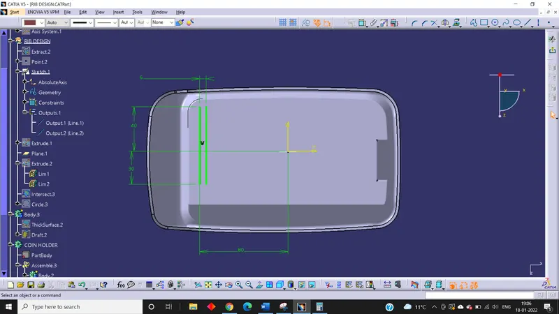
For rib 2 we offset the sketch.1 to 6 mm considering the thickness of the rib to 0.5 mm both sides.
Since, spacing should be done in such a way that height/width < 3 mm
Here, height = 12.5 mm
Width = 5 mm (1 mm for thickness of both ribs)
Spacing = 12.5/5 = 2.5 mm < 3 mm
After that all the steps should be repeated as like for Rib 1.
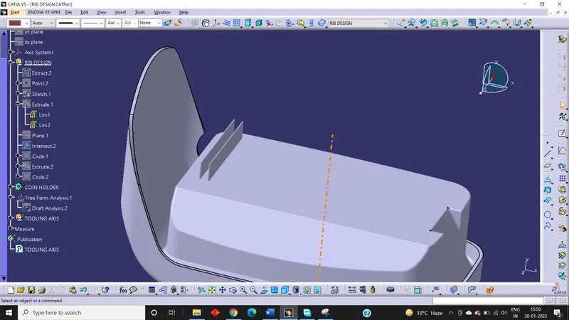
Now, we check the rib root thickness and spacing for both ribs.
Final Draft Analysis:
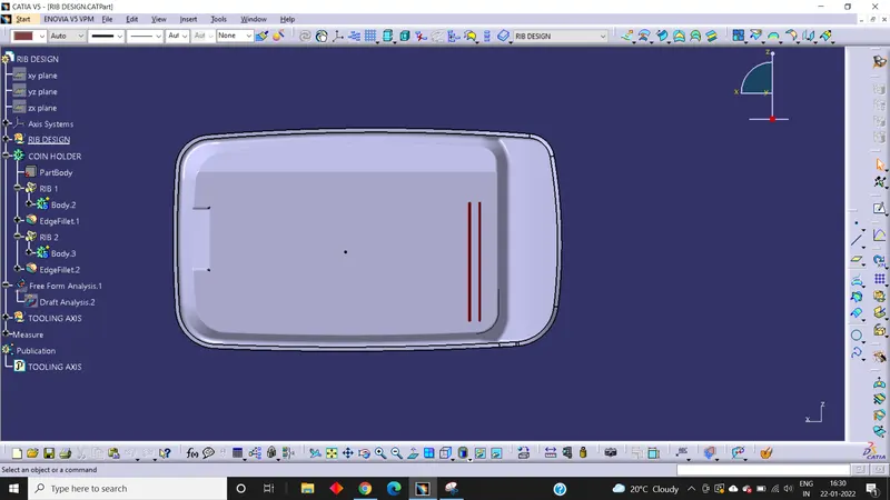
First of all, change the view to Customize View Parameters and then check material mode selected and perform the same operation as done previously while we did in doing draft analysis.
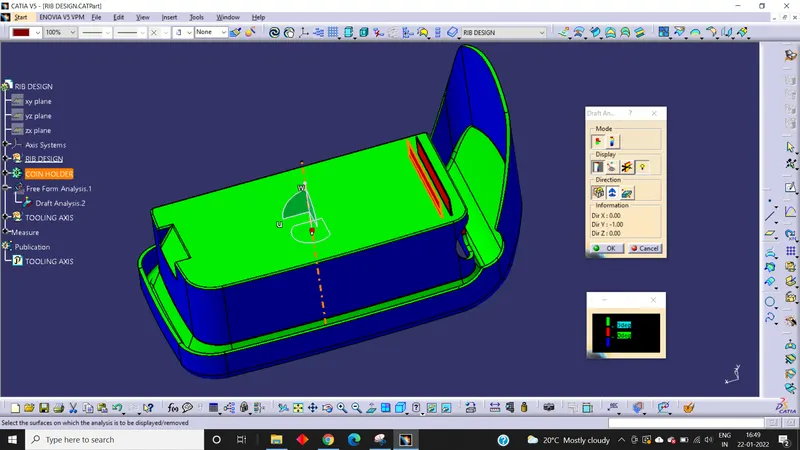
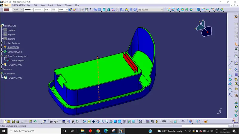
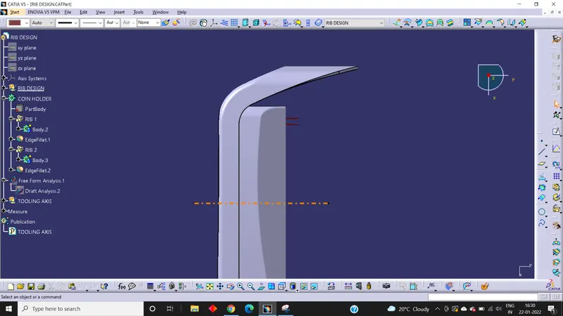
The red color on the ribs describes that the draft is given between 0 degree to 3 degree on the ribs.
3D View:
Isometric View:
Front View:

Side View:
Top View:
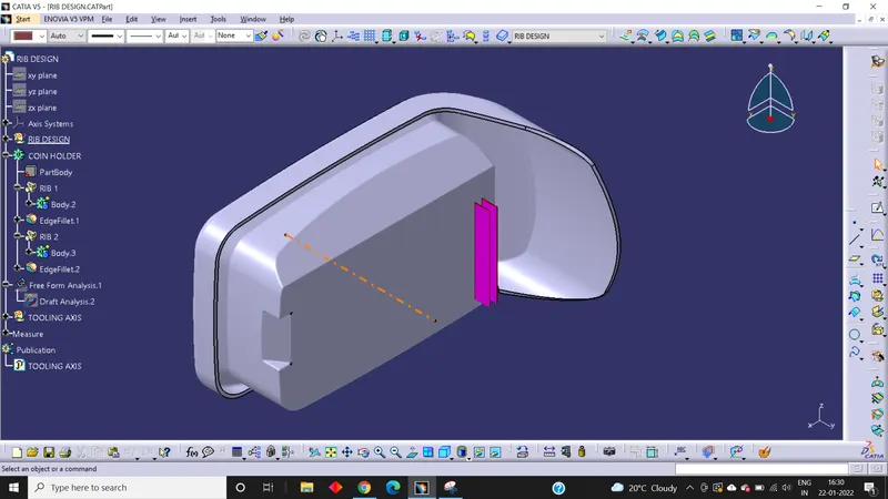
Tree Structure:
Conclusion:
The Ribs for the Centre console coin holder were created from the given Coin Holder Cad following the design rules for the rib.