Week 9 - Attachment Feature Creation - Challenge 1
ATTACHMENT FEATURE CREATION – CHALLENGE 1
RIB DESIGN
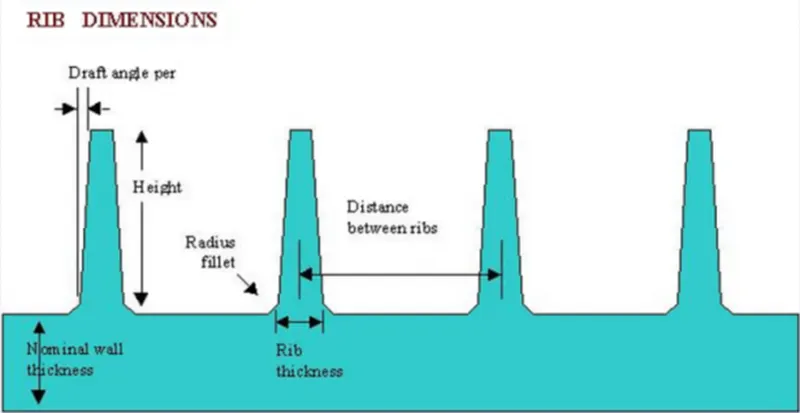
Rib design is the given to any of the plastic component in order to provide the strength to the wall of the component without increasing the wall thickness. This is another useful method in which the cost of the component can be reduced just by providing the ribs if the product needs to be having more strength, instead of replacing or increasing the wall thickness the ribs are designed. But to design the rib is not the easy task as it seems, we have to undergo through the plastic product design rules and the terms along with some calculations. The ribs can be seen in figure below.
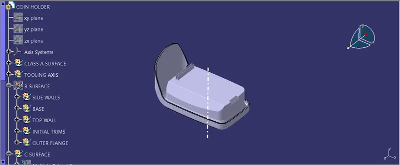
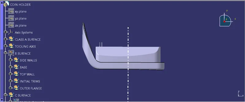
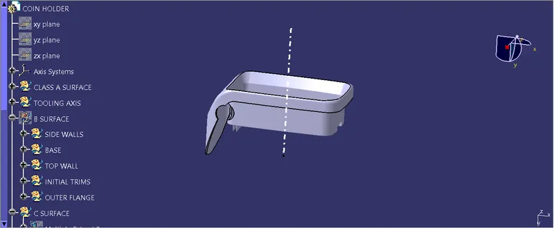
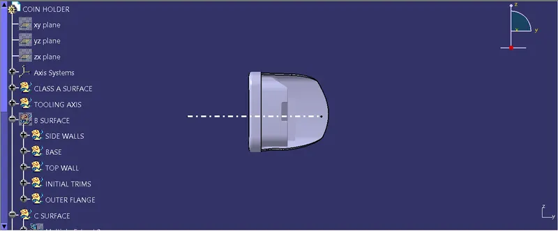
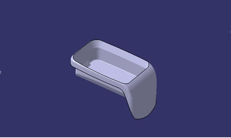
The component on which the ribs are to be designed is the coin holder as shown in the figure below.
Now here the ribs are provided to the B side i.e the base side of the component in order to provide the strength to the component without increasing the base wall thickness.
So here initially the base surface is extracted and the position sketch is drawn on to it as shown in the figure below.
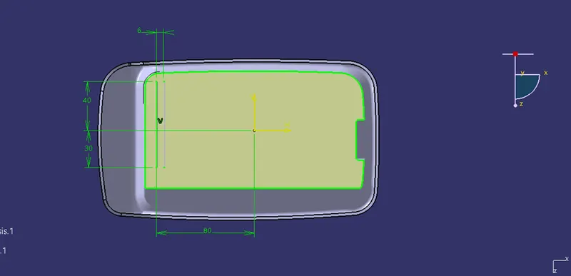
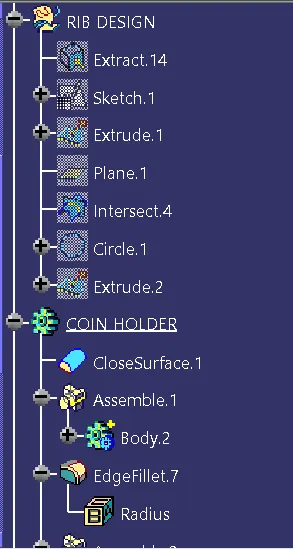
Then this sketch is extruded in the perpendicular direction of the component. Now here comes the design rule for the height of the rib. According to the rule the height of the rib should be 5t i.e 5 * thickness of the component. So here the height of the rib is 5 * 2.5mm = 12.5 mm.
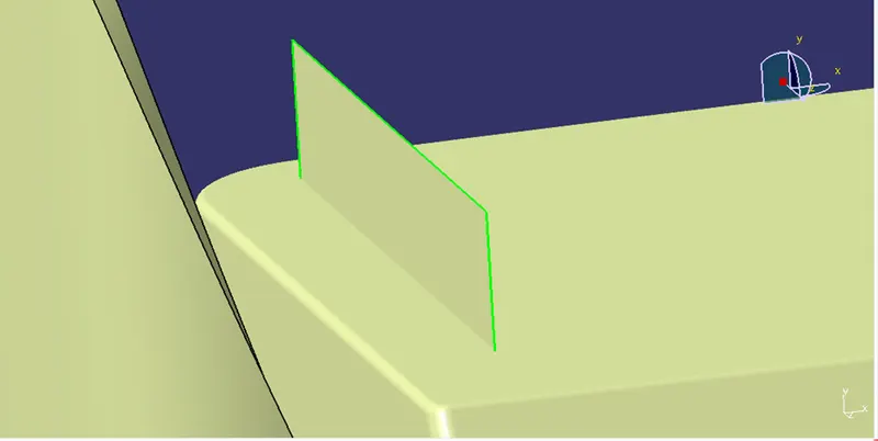
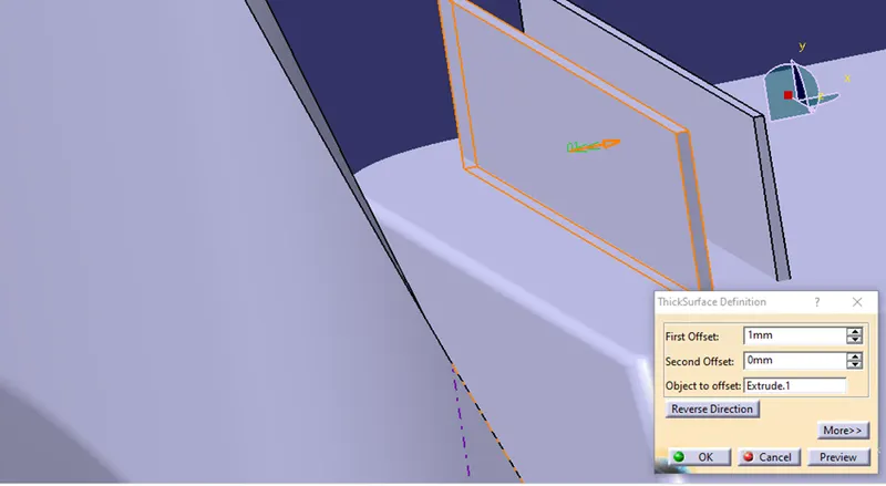
Now as the height given to the rib is 12.5mm, now the thickness is to be given for the rib. So the new body is inserted and the part body interface is open and then the thickness command is used to provide the thickness to the rib. But according to the design rules the thickness of the rib should be 0.4 to 0.5t i.e here 0.4 * thickness of the component. So 0.4 * 2.5 = 1mm. Hence the thickness given here to the rib here is 1mm as shown in the figure below.
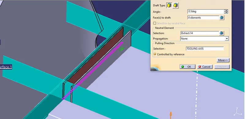
After providing the thickness, the draft is to be given to the ribs according to the design rules. So the draft angle according to the rule should not be more than 0.5 - 3 degree. This is because the upper thickness of the rib should be more than 0.75mm and not less than that. If the thickness is less than 0.75mm then that is considered to be the defective and inefficient rib design. So here the draft angle is given as 0.5 degree with the neutral element as the base extract and the tooling axis as the pulling direction as shown in the figure below.
Here comes the final step of the rib design i.e giving the fillet value. According to the plastic product design the fillet value should not exceed more than 0.25mm in case of ribs. This is the optional radius of 0.25mm that is given to the ribs as shown in the figure below.
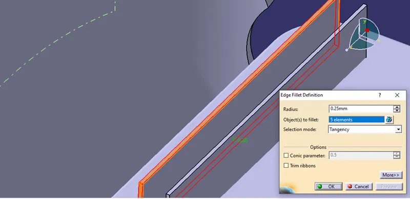
Now as our on rib is designed we have to verify that the design of the rib is following the design rules or not. So here the intersection of the XY plane is taken with the whole coin holder body. After intersection we get the following figure.
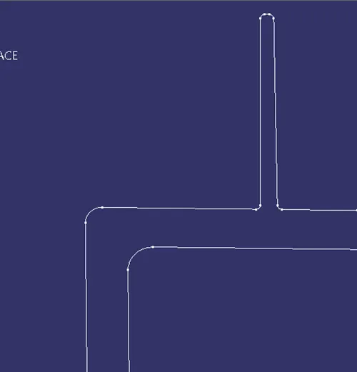
We have to check the rib root thickness that should not cross the 30% of the thickness. So here the lines are extracted and the tri-tangent circle is drawn which looks like the figure shown below.
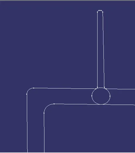
Now as we measure the dimension of the circle we get the value 2.686mm which is more than the actual thickness of the component. Hence our design of the rib is safe.
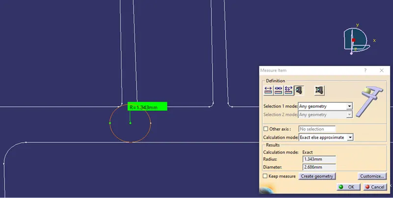
But our next task is to design the same rib again at the certain distance. So to design such rib again we need to find what should be the distance between the two rib.
Now again the design rules are used. So according to the design rules of the plastic product design the preferred ration between two ribs are 2:1 and 3:1. Again the distance between two ribs is given as 2t i.e 2 * thickness of the component. So here are certain ways that are preferred to find the distance between the ribs.
Here if we take 3:1 ratio we will get ,
12.5mm / x = 3mm
Here x is the spacing between the two ribs
So,
x= 12.5/3
therefore x will be = 4.16667mm
which will be 5mm spacing between them but as we give the 5mm spacing we have to consider the rib thickness also, if we don’t consider we will get the spacing of 4.079mm which is inappropriate. So here the spacing given between the two ribs is 6mm. as shown in the figure below.
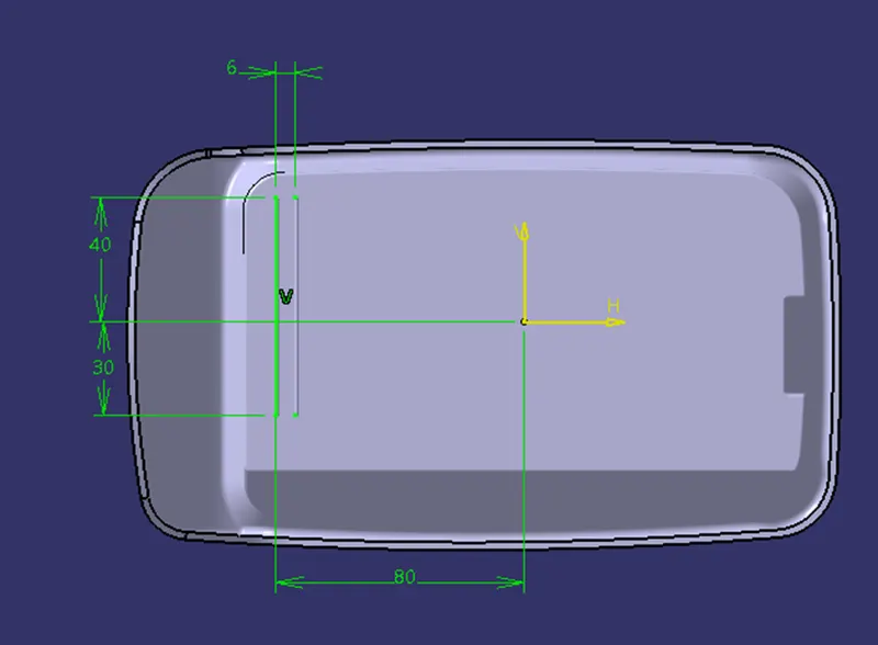
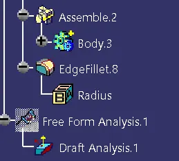
After giving the distance between the two ribs then the rest of the design procedure is followed as the previous rib and hence we get the ribs fully designed as shown in the below figure.
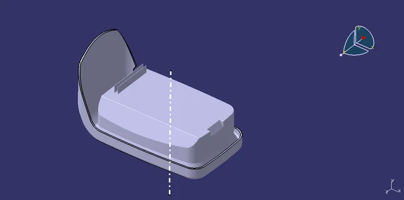
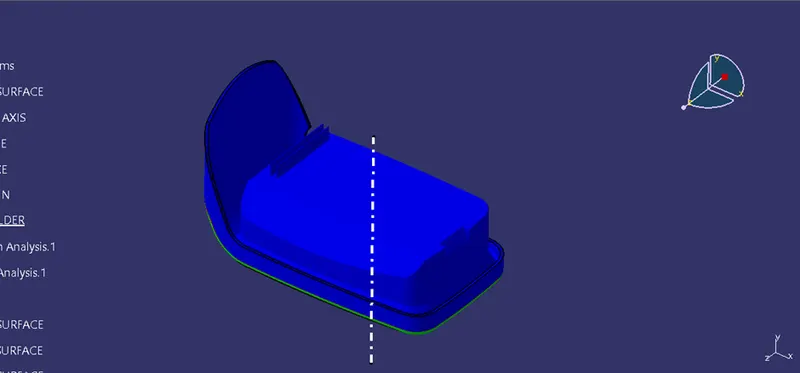
Hence the ribs are fully designed.
IMAGES :-