Week 9 - Attachment Feature Creation - Challenge 1
FEATURE ATTACHMENT CREATION USING CATIA V5
OBJECTIVE: The main aim of this challenge is to create a rib on a coin holder solid body which is previously designed and to perform a draft analysis on the final solid body with rib and to prepare a detailed report explaining all the procedures we have followed and to perform checks to make sure the design is satifying all the required considerations of design.
INTRODUCTION
DRAFT ANALYSIS:
Draft analysis is a analysis which is performed on the objects or bodies in order to check the draft angle of various faces in a particular direction which is tooling direction.
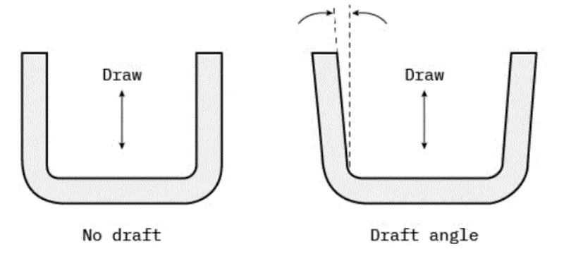
Every part like sheet metal parts which are generated from a Press Tool or some forming tools, may be the plastic parts which generally come out from the plastic moulds and maybe the casting parts, all such kind of parts required some drafted face on the surfaces which are parallel to the tooling direction. If we don't provide drafts on the surface then it will stick to the mould surface and whenever the mould is in motion they will destroy the surfaces or also reduced the finishing of surfaces.
The Tooling Direction is basically the direction that the mold pulls apart. The mold is built in two separate pieces, basically. You have a Cavity side and you have the Core side. The Core pulls apart from the Cavity and that's the Dyeline or the Tooling Direction.
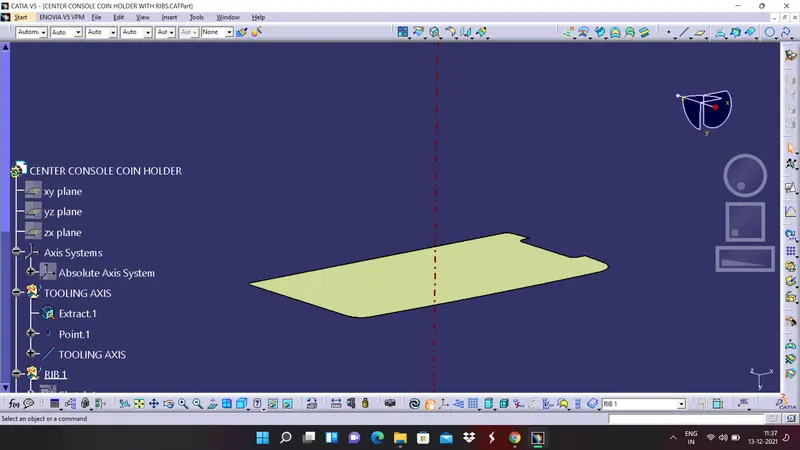
And the axis which represents the tooling direction is called tooling axis and selection of this is axis is a crucial step while performing the draft analysis.
RIBS
Ribs are thin, wall-like features typically designed into the geometry of a part to add internal support to walls or other features like bosses. They acts like support and increases the strength of the component.
CREATION OF TOOLING AXIS
1. Extract the base surface of the the coin holder solid body.
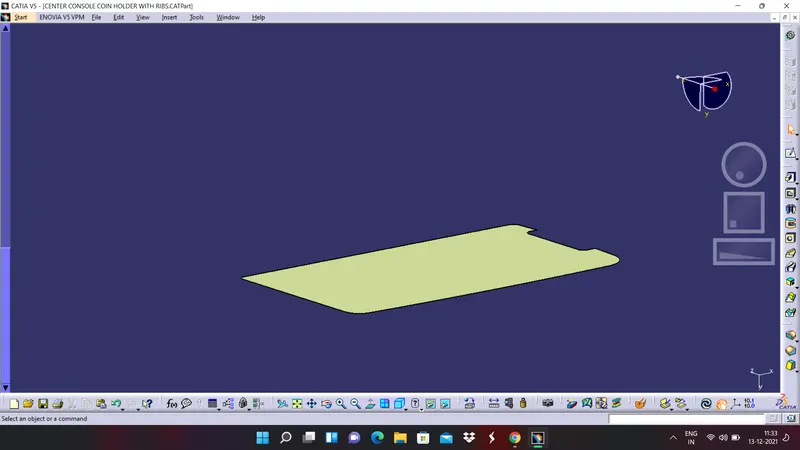
2. Create a point and it should be at the centre of the surface.
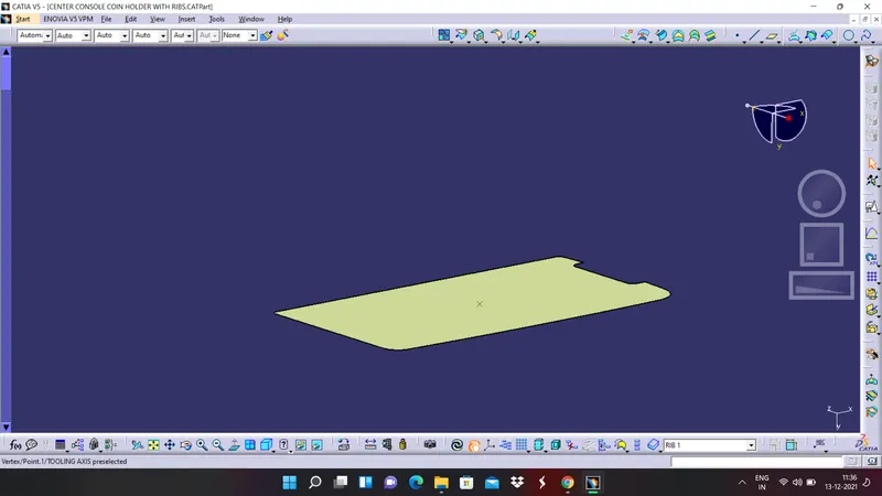
3. Create a line by using line command and selecting point and direction as the line type.
RIB CREATION ON COIN HOLDER
1. Create apositioned skecth on the top plane by using projection sketch and make sure that the sketch is iso constrained
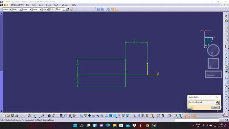
2. Extrude the sketch in respective direction with proper lenght
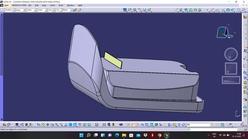
3. By using thick surface command in part workbech give the required thickness to the extruded surface and apply draft to the required faces by giving required angle and assemble it to the coin holder body.
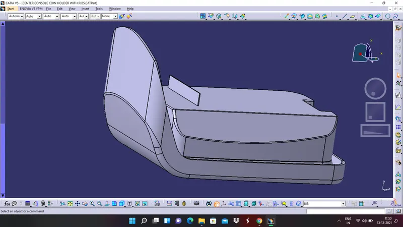
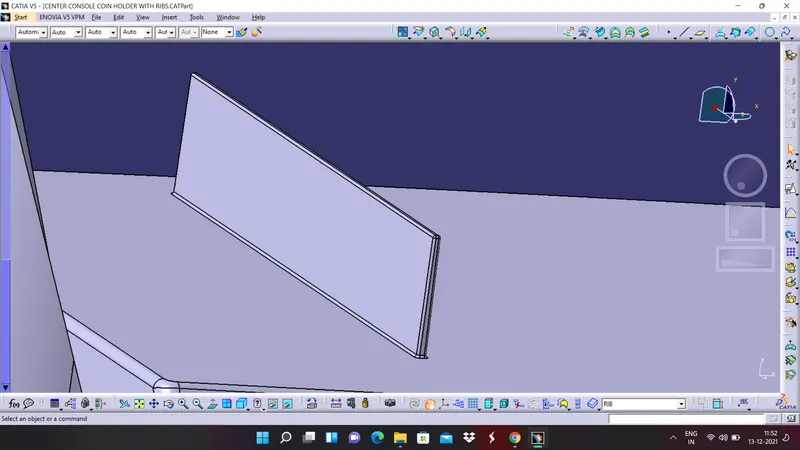
4. Apply edge fillet by choosing all the edges by giving proper radius to it.
CHECK FOR DESIGNED RIB
First we will see the the image of design requirements or rules for the rib creation.
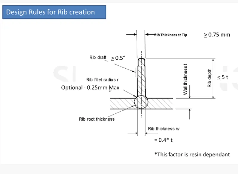
1.CHECK FOR THICKNESS OF RIB AT TIP:
From the image we cab see that the thickness of the rib at tip is to be greater than 0.75 milli meters and now check what the thickness that our rib have,
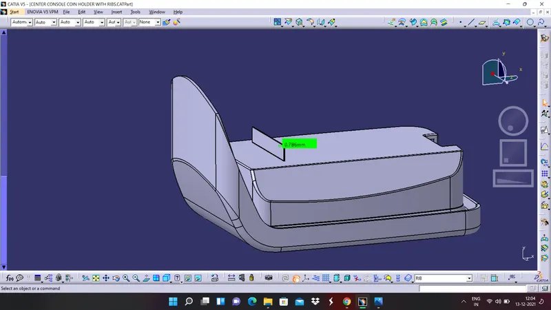
So here, we have a thickness of 0.786 millimeters which is gretaer than 0.75 milli meters and hence our rib has satisfied the first condition.
2. CHECK FOR RIB DEPTH:
From the image we can see that the rib depth should be less than or equal to 5 times the thickness of the wall. we know that the wall thickness is 2.5 millimeters and so the depth of our rib has to be equal to or less than 12.5 millimeters now check that,
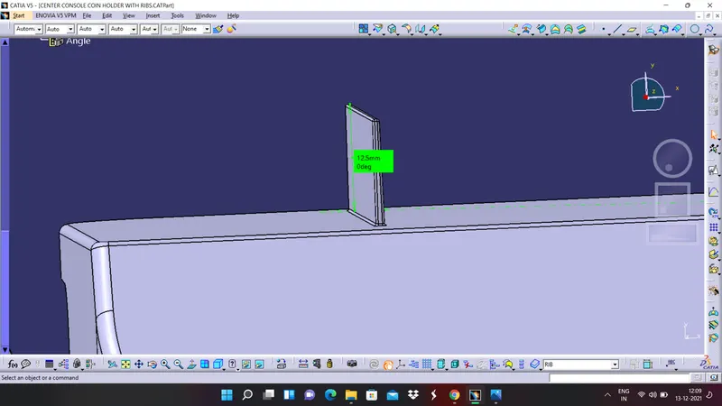
So hence our design is also satisfying the second condition.
3. CHECK FOR RIB THICKNESS:
The rib thickness should be equal to 0.4 times of the wall thickness, it means the thickness has to be 1 mm.
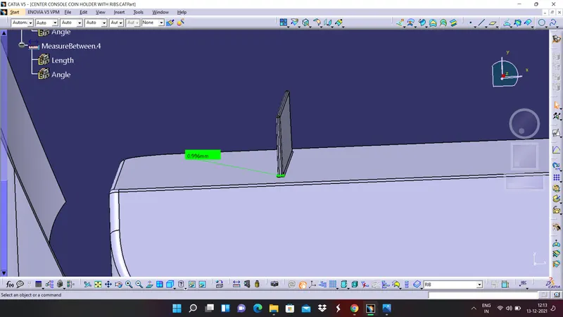
And the rib design has satisfied this condition also.
4. CHECK FOR RIB ROOT THICKNESS:
for this create a plane by taking XY plane as reference and point as the point which we have created for tooling axis.
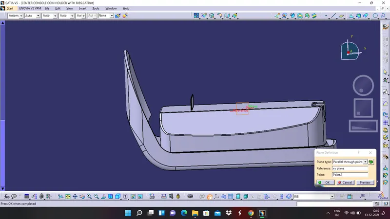
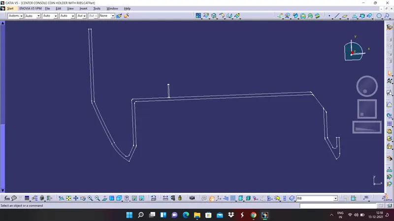
Create an intersection between this plane and entire solid body and hide all the things except the intersection curve.
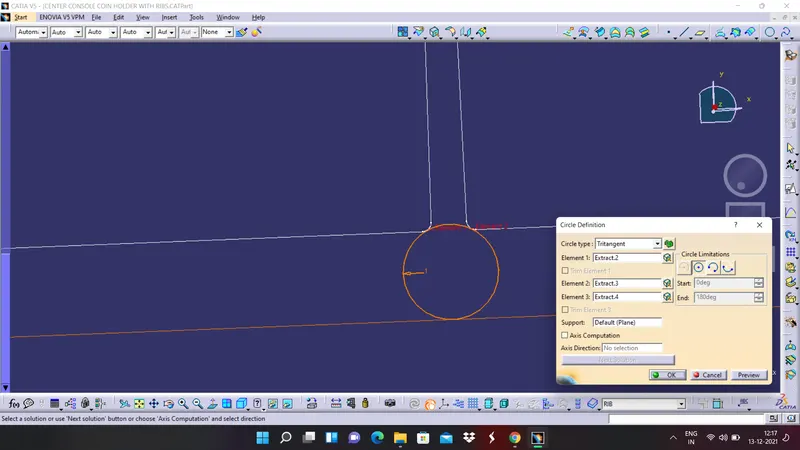
now at the rib area create a tritangent circle by extracting the edge fillets.
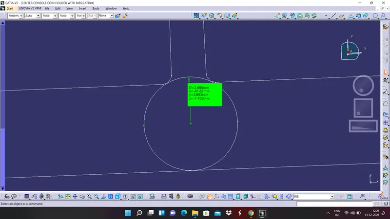
Now measure the diameter of the circle and we can say that the design is satisfying this condition also by seeing the diameter value.
5. CHECK FOR RIB FILLET RADIUS
From the image we can see that the radius value must be a maximum of 0.25 milli meters. let us check how much radius we have for rib fillet,
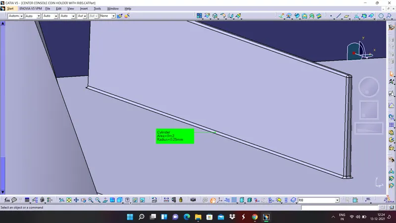
Since our fillet value is 0.25 milli meters only we can say that our design has satisfied this condition also.
6. CHECK FOR DRAFT ANGLE.
From the image what we have given in the challenge the draft angle must be greater than or equal to 0.5 degrees now measure the draft angle what we have,
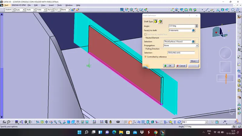
so we have given draft angle as 0.51 degrees which is greater than 0.5 degrees our design satisfies all the design rules and our design is safe.
DIFFERENT VIEWS OF FINAL SOLID BODY WITH RIB
ISOMETRIC VIEW
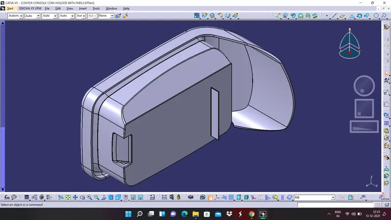
FRONT VIEW
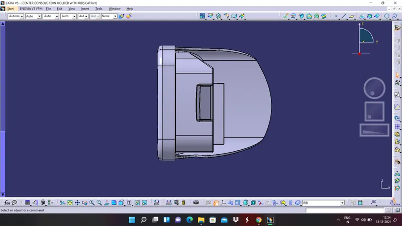
SIDE VIEW
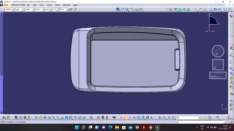
TOP VIEW
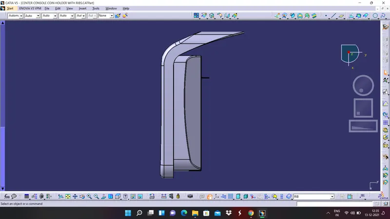
DRAFT ANALYSIS ON COIN HOLDER WITH RIB
Click on the draft analysis tool bar and drag the compass on to the body and align it with the toolin axis which we have created at the beginning. click anywhere on the part body and observe the colours. The expanded colour code values are shown in below picture,
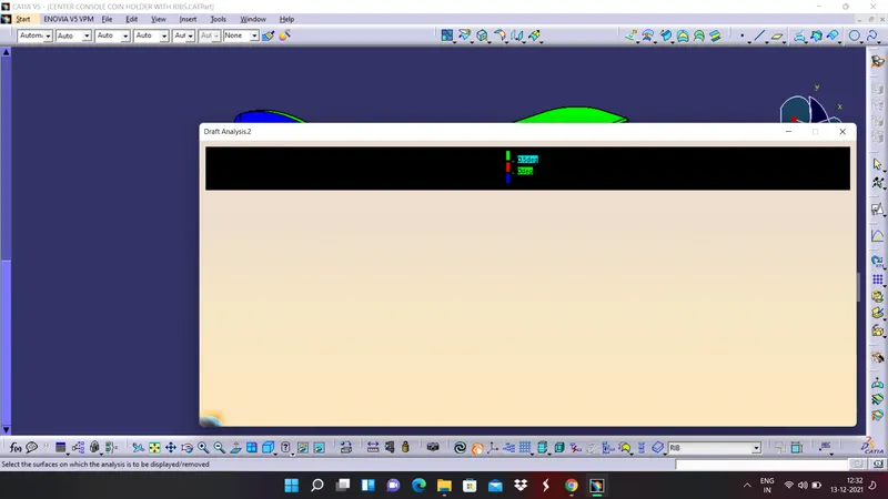
Now let us observe the colour codes on the part body in different views,
ISOMETRIC VIEW
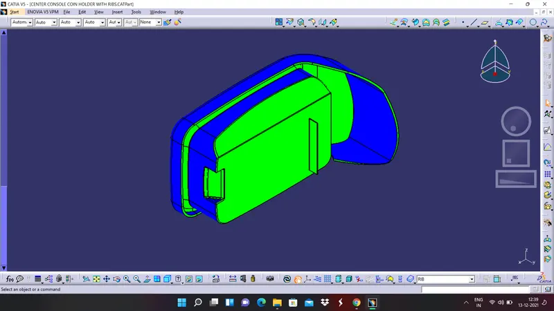
FRONT VIEW
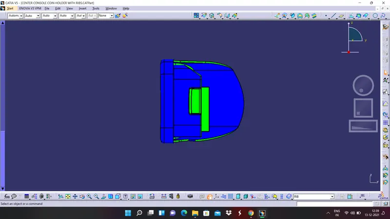
SIDE VIEW
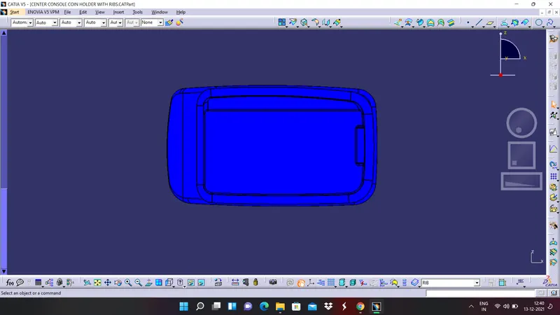
TOP VIEW
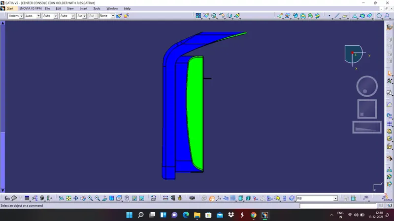
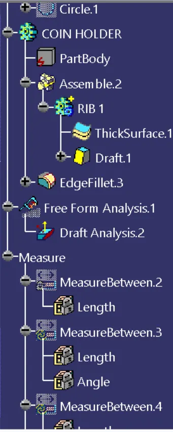
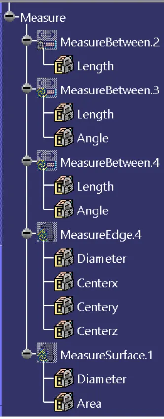
PART NAVIGATOR
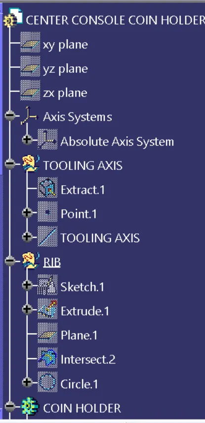
CONCLUSSION
Hence we are concluding that we have created a rib profile on the part body and the design is satisfied all the design rules which we have to follow. Draft analysis is performed on the part body and the results are satisfactory. A report has been prepared by explaining all the things in a detailed manner.