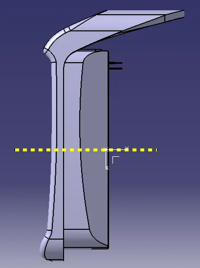
Week 9 - Attachment Feature Creation - Challenge 1
AIM:
Create the rib for the Centre console coin holder considering the design rules mentioned in the video.
OBJECTIVE:
- Ensure Proper Tree Structure
- Geometrical sets should have a proper name based on the sketches present inside of it
- All the sketches should be created under the Geometrical set
- A detailed report should be done explaining the draft analysis and the tooling axis creation.
- An explanation should be given on the way of creating the tooling axis particularly the Bisecting method.
PROCEDURE:
Step-1: Connectivity check
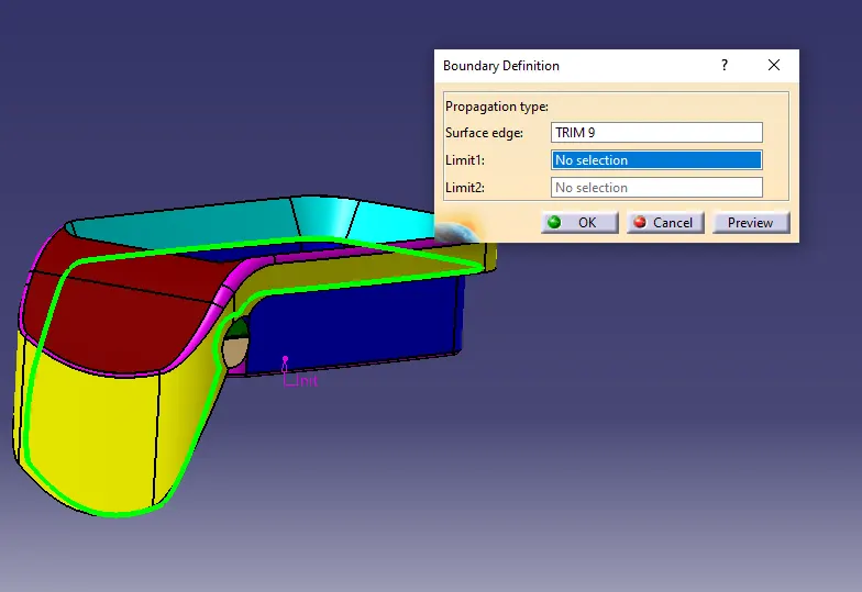
- First we have to verify the part design using join surface option by simply selecting the class A surface .
- Another method is create a boundary layer of surface and disassemble it from the boundary layer from the surface.
Step-2: Create tooling axis (Bisecting method)
- Create a reference point by selecting the center circle of surface.
- Then create the axis for the surface to easily define the tooling axis.
- simply select the point and xyz plane.
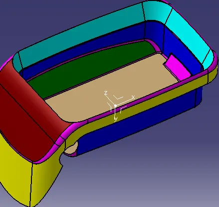
- To get a dummy tooling axis in x direction.
- Use the intersection command, to get a wire diagram of surface in x direction.
- Use multiple extract to separate the bottom face for tooling axis definition.
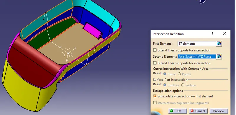
- select the intersection command, select first element is plane of dummy axis say zx plane, select second element as class A surface, click ok.
- The draft angle of x direction is created to get the tooling axis of x-direction.
- We will get the tooling axis in x-direction and also define its line color and thickness
- After the dummy axis definition, select the tooling axis of x to bisect using line command.
- The tooling axis for draft analysis is formed.
- Use publication command to publish the class A surface and tooling axis.
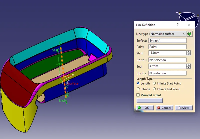
Step-3: Perform draft analysis
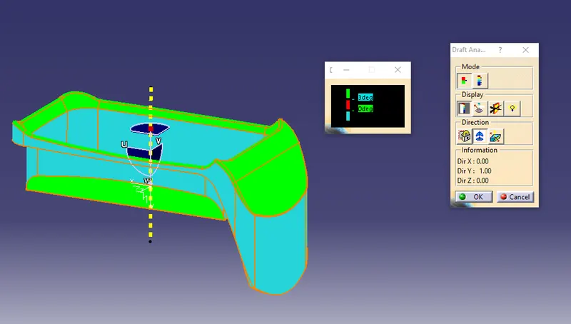
- Select the draft analysis command, ensure the material feature is used.
- Use quick analysis mode, display color scale option.
- Click on compass command on direction, drag and drop it in tooling axis.
- The draft should show green surface which is feasible draft angle.
- If red is shown not feassible draft angle and for blue negative draft angle.
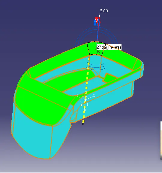
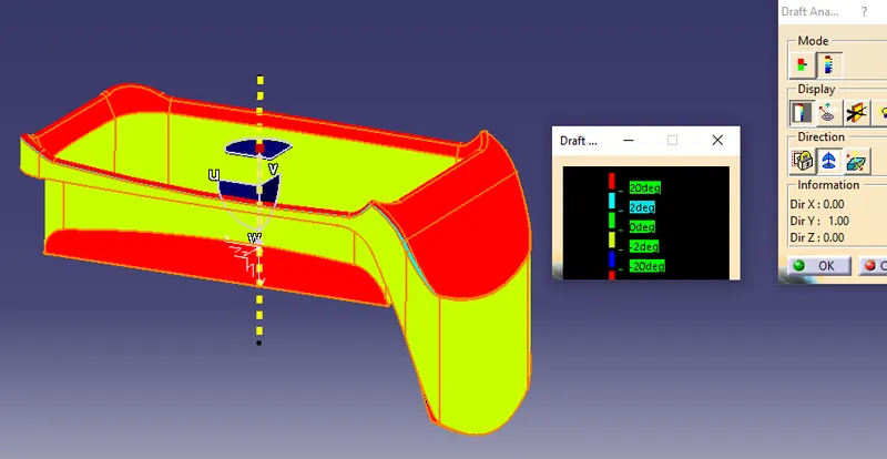
- Use analyses under running point, to ensure same angle on symmetrical direction.
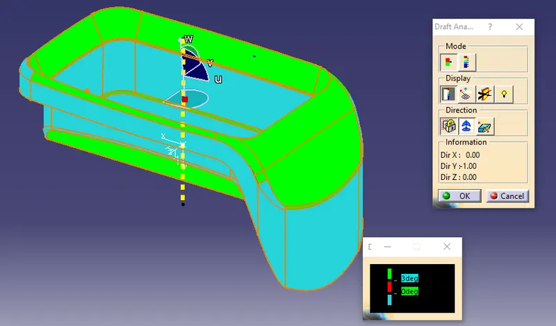
- Below is fully analyze mode to get the varied angle in class A surface.
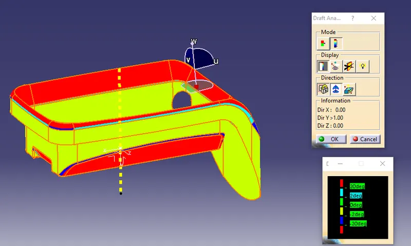
- Below is fully analyze mode to get the varied angle in class C surface.
Step-4: Create rib 1
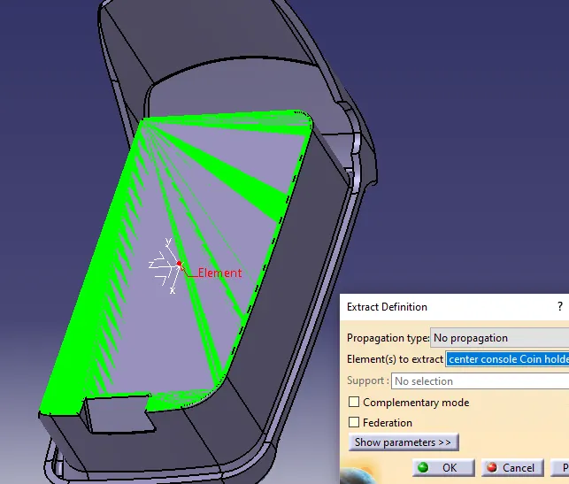
- First extract the surface where we have to create the rib design.
- Then create a sketch of a line which is ribs baseline and constraints should apply.
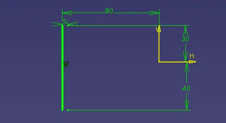
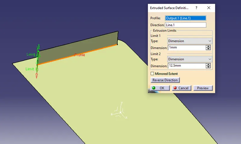
- Extrude the line for 5t where t is thickness of the object (2.5mm).
- Also extended the other side for 1 mm or else the object can't be assembled.
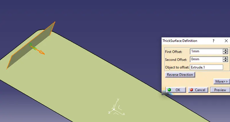
- The thickness of rib is 0.4t say 1mm apply it uisng thick surface option.
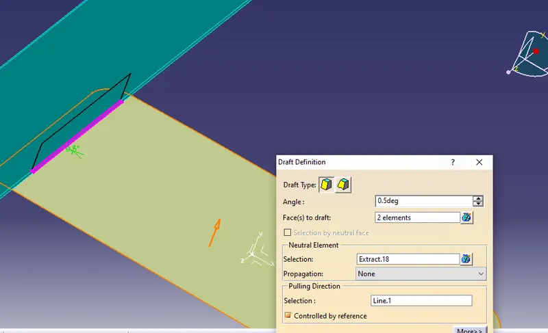
- Apply draft angle of 0.5 deg.
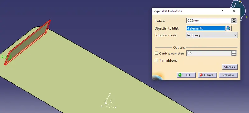
- And also apply edge fillet as 0.25 mm.
- Create a body and use boolean assemble option.
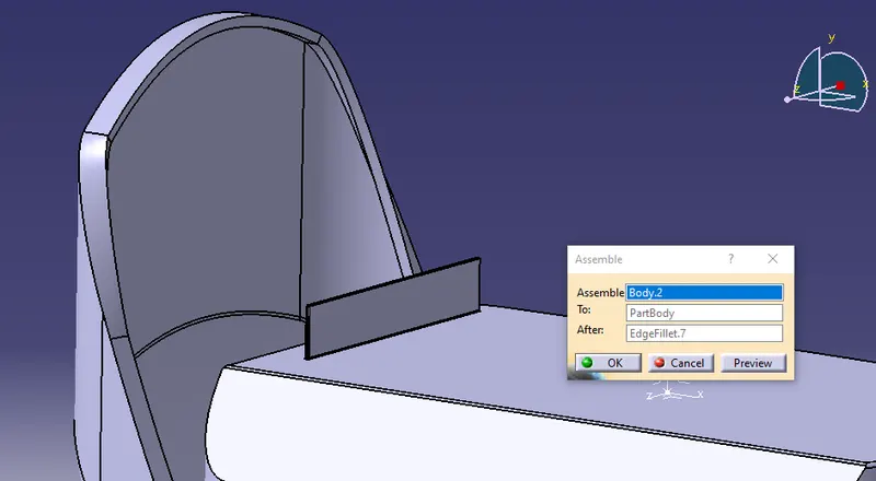
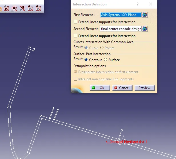
- use intersect option to create a wireframe of the assembled object
- Create rib root thickness by using circle option as tritangent.
- And extract from the three lines where the circle has to lie.
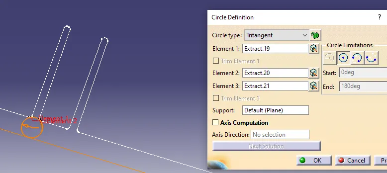
Step-5: Create rib 2
- Do same procedure to attain the rib 2 design of distance 5mm apart with same dimensions.
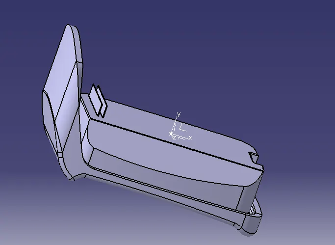
ESULT:
- Tree structure
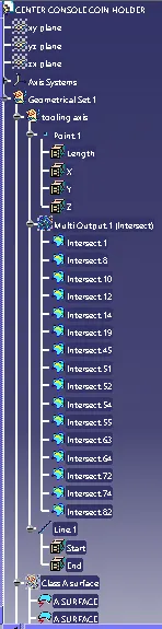


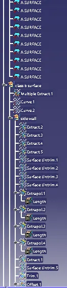
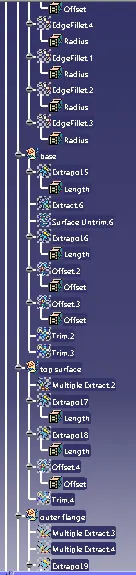
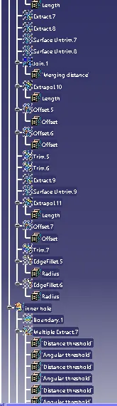
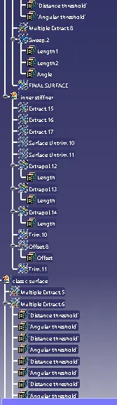
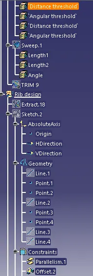
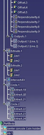
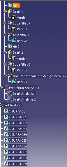
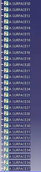
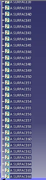
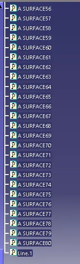
- Isometric View
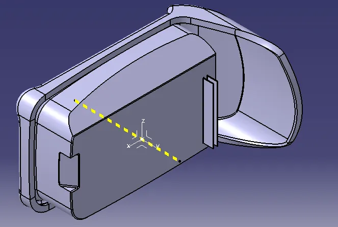
- Front View
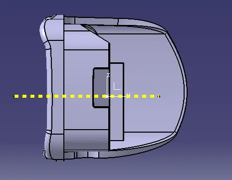
- Side View
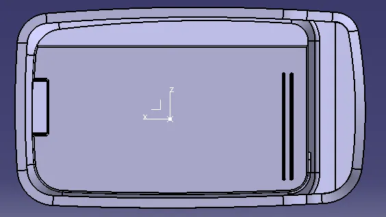
- Top View