Week 9 - Attachment Feature Creation - Challenge 1
Aim :
Create the rib for the Centre console coin holder considering the design rules
Detailed Report :
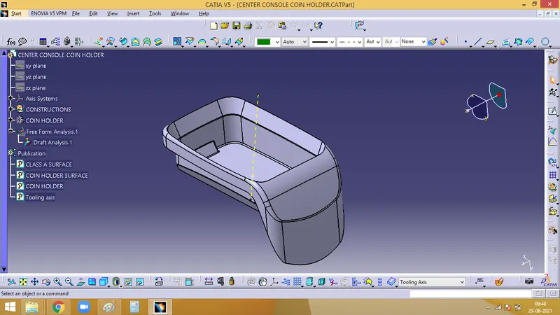
1. Creating tooling axis
Tooling axis is the direction along which the core and cavity opens and closes. Draft angle is required for every face for smooth ejection of teh component from the core section. For this only, draft analysis is done for which primarily a tooling axis is required. In case of comlex designs more than one tooling axis might be needed for side core.
As the base is flat and it at zero degree, a normal line can be created, which asts as a tooling axis
2. Performing Draft analysis
Initially the material mode has to be set and open the feature draft analysis dialog box. Pick on the compass symbol and place it in line with the tooling axis.
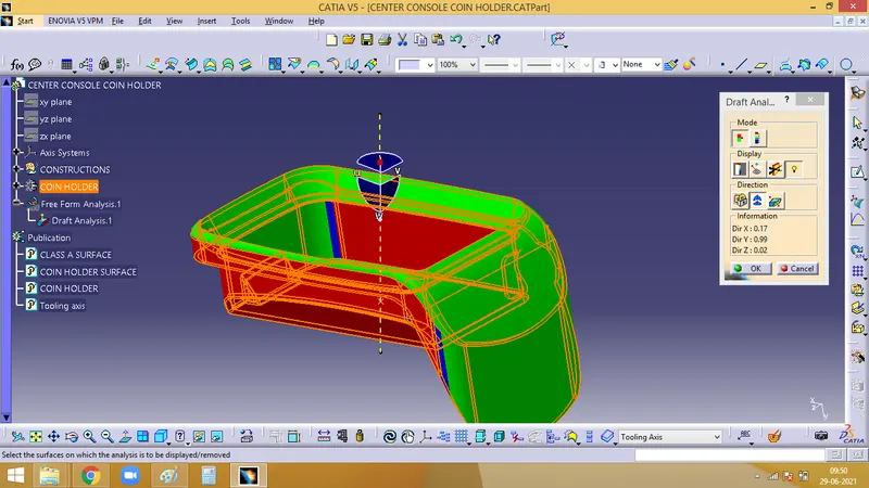
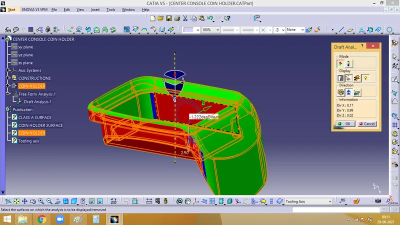
Now we have to check for the draft. Click on the surface and check for the colour from the draft analysis 2 dialog box. The minimum draft needed is 3, which is checked here. If any surface is red, then it has a draft angle less than 3.
With the help of Analysis under the running point icon, we can check the draft angle of each face
3. Creating Rib :
Extract the Base surface, and create a line on it
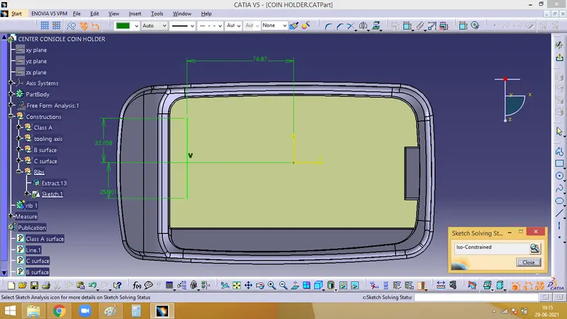
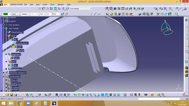
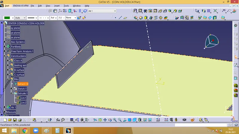
Extrude it and in the part work bench thicken the same extrude. The height of the extrude has to be 5 times the part thickness and the thickess has to be 0.4 times the thickness of the component. And the final result will be as below image
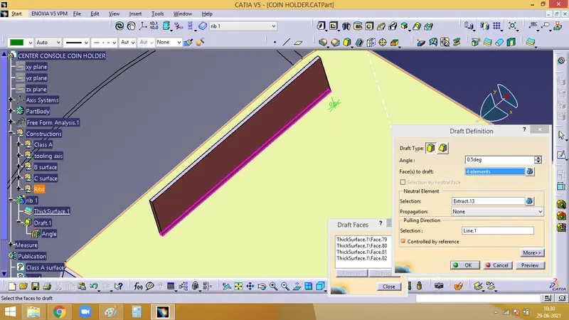
Next is to give the draft for the rib. There has to be min. 0.5 deg draft on each side of the rib
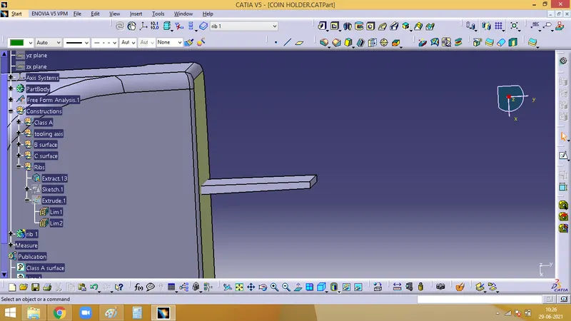
It is observed from below image, that the base is thicker and thinner at the top
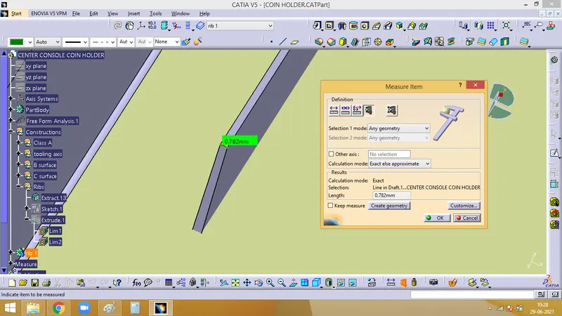
The top edge of rib has to be more than 0.75 mm thick
Add the rib to the main coin holder body using boolean operation
Now, fillet has to be given to all the edges of the rib. A min of 0.25mm is given
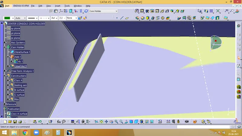
For, Rib Root thickness, we need to take a section through the middle of the rib. Then create a tritangent circle in order to measure the thickess along the rib
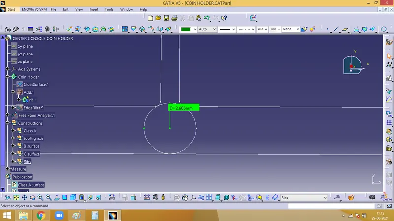
From the below image it is observed that the rib which we have created is of the right dimension following the design rules
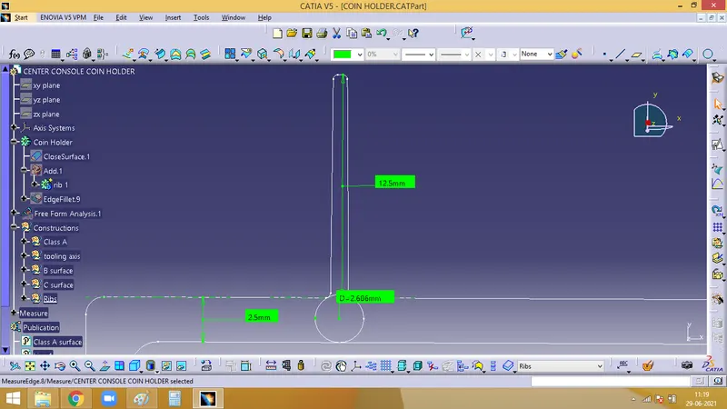
4. To create more ribs
Offset the intital sketch created to a distance measured at the ratio of 3:1 i.e height:width of the rib, and repeat the same operations of extrude, thickness, draft, fillet as done in the first rib
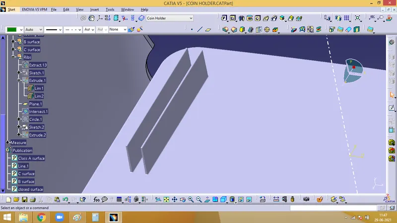
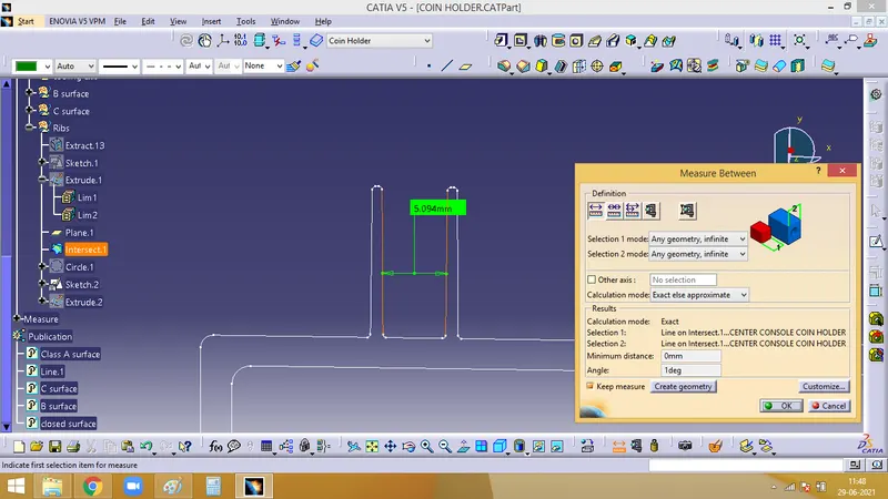
The below measurement is acoording to the 3:1 ration according to the design rules
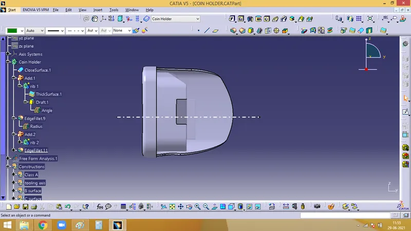
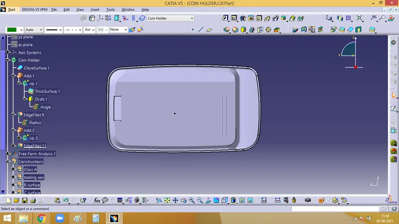
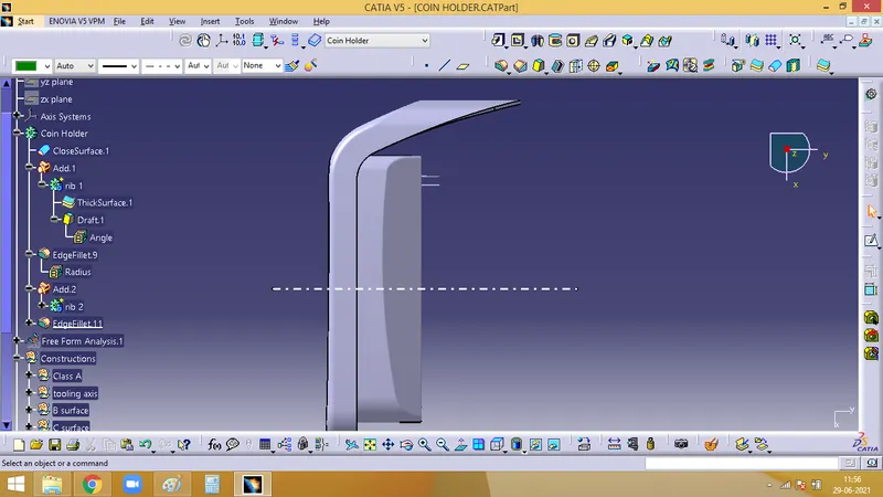
Views of the final component