Week 9:- 2D Detailing Challenge
Whar are the Drawing templates?
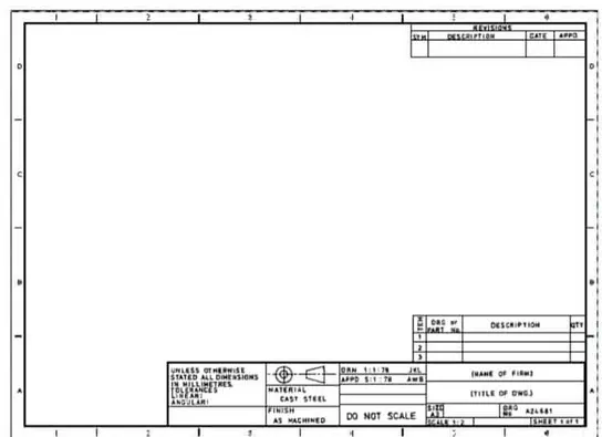
These are Standard formats per customers, which are used for detailing of varoius parts and units in a fixture.
A templet provides details about method of projecton used for reading the drawing, views necessary to understand each detail dimension of the part to manufacture.
Each templet has very detail informations about the fixture and its parts. Which include- Material, Heat Treatment, Surface finish requirement, tolerances, Sheet size, reviison, date.
It has all about the drawing creation like date and designer, revision, updates and all.
It should be used at very start of project.
There are various types of templets, can be used as per customers requirement.
They are available in different sizes like A4, A3, A2,A1, A0.. depending upon size of part.
What do you understand by Angle of projection?
Engineering drawings are a richly detailed method of representing three-dimensional things on a two-dimensional surface such as paper or a computer screen.
By providing a variety of views of different sides of an object in a single image or by representing all three dimensions of an object in a single image.
These are known as Othographic views of a 3D object.
Objects can be displayed as 3-D or Multiview projections.
Multiview projections on the other hand are used to compensate for the shortcomings of 3-D projections.
There are different viewing angles, it is easy to depict object details.
Multiview projections are good for revealing the intricacies of an object.
In Multiview projections, dimensions can be easily displayed, and most details remain undistorted.
- Orthographic Projection – The orthographic projection is the conventional method of Multiview projection in engineering graphics.
angle of projection is identified based on the quadrant the object that is placed for projection of Views. First Angle projection If the object is placed in the First Quadrant for viewing the projections, the angle of projection is identified as First angle Projection.
What is the First angle & Third angle projection? and why can't we use the 2nd and 4th angle of projection?
In orthographic views, Ref. Planes and views are named as-
The reference planes include:
- Horizontal Plane (HP)
- Vertical Plane (VP)
- Side or Profile Plane (PP)
The viewpoints include:
- Top View (TV) – Projected on HP
- Front View (FV), Projected on VP
- Side View (SV) – Projected on PP
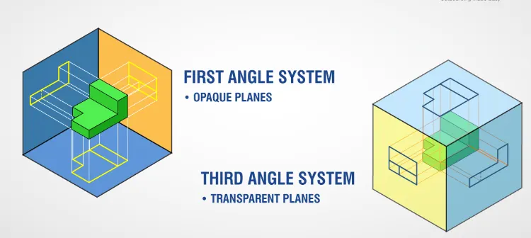
By placing object in any quadrant, projections are taken. Like first angle , second, third and fourth angle method of projection.
Eg. If object is placed in first quadrant, FV wil be on VP, and TV will be projected on HP.
In order to place these two views on a single plane, by rule of projection, HP can be rotated by 90 deg, clockwise. (VP cant be rotated, anticlockwise rotation not allowed).
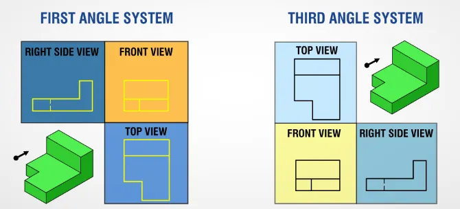
Hence in first angle method, FV is on VP and ABOVE HP,
TV is on VP and below HP. and Left side view is placed on right side of FV.
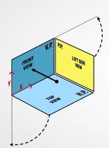
In case of Third angle the position of FV is ON VP, Below HP and LHSV on Left side.
TV is on VP ABOVE HP.
If we placed object in SecondQuadrant, FV will b on VP, and below HP, after rotation of HP 90 deg. clockwise, FV and TV will overlap, and will not properly informative.
Same thing happens if an object is placed in Fourth quad.
This is the reason, 2nd and 4th method of projection is not used at all.
It is crucial that all components work well together, with functional assemblies, multi-part products, or parts with complex functionality.
All relevant fits and features need to be specified in a way that impacts the manufacturing process and its related investments the least, while still guaranteeing functionality.
What is GD&T? What are the benefits of GD&T?
There is no any manufacturing process, which can manufacute a part with 100% accuracy.
There are several reasons for this and many limitations.
Hence in an engg. drawing, a dimension need to add a tolerance value( maximum and minimum acceptable value) in order to define a dimension completely and considering machining process limitation and its functionality.
Closer the tolerance value, machining cost is higher.
To make a desing more detailed, tolerances are provided wherever specific functionality of the dimension is required.
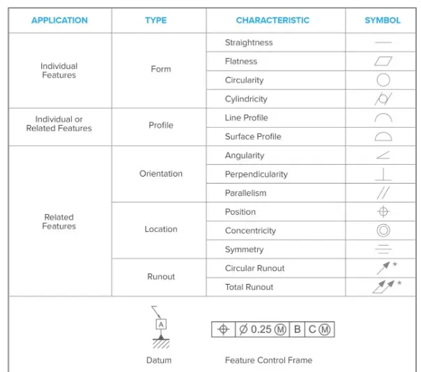
GD&T establishes a library of symbols to convey such design intents.
Geometric Dimensioning and Tolerancing, is a system for defining and communicating design intent and engineering tolerances that helps engineers and manufacturers optimally control variations in manufacturing processes.
It includes information about Machining process, roughnes, tolerance, surface finish various datum planes.
As it is symbolic language, it is accepyed and used universally.
GD&T is the system that allows developers and inspectors to optimize functionality without increasing cost.
Benefits of GDNT-
GD&T allows the designer to communicate the design intent, and is a focus on the function of the part.
By focusing on the function of a part, less important tolerances may be loosened.
Loosened tolerances result in a part that is easier and cheaper to produce.
1. Clear Measurement Requirements
When it comes to the inspection of a part, GD&T has a great advantage over coordinate tolerancing.
Datum planes on a features provide importance the feature and ultimately force to measure all features form the specific feature.
2. Focus on Function-
When GD&T is used in a design, the focus is on the function of the part.
3. Larger Tolerance Area
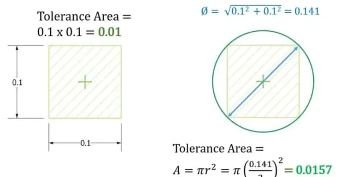
When we compare the tolerance area of the square and round zones, we see that the round tolerance zone is 56% larger. Having a larger positional tolerance zone means that there are additional points where the center of the hole in the manufactured part could land and still be within the drawing specification. This results in a part that is easier and cheaper to produce!
4. Bonus Tolerance-
Im addition, when a feature is designed for MMC, one can get bonus tolerance,
Explain all the symbols used in GD&T?