Week 9:- 2D Detailing Challenge
1. What are the Drawing templates?
Drawing templates are basically the drawing standards as per the customer specifications. Drawing templates are the formats used fro detailling of diffenrect parts or units of a fixture.
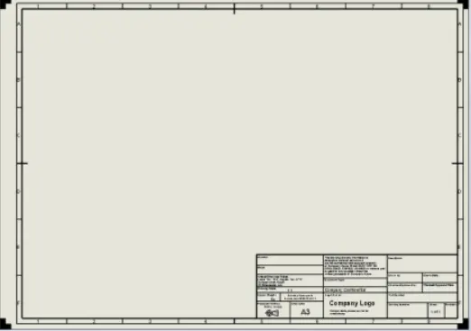
The "n" numbers of details, that are available on the templates and are useful for various machining process, such as machining finish, surfaces treatments, tolerances, material, name of the parts, name of the assemblies etc.,
Drawing templates has n number of information such as:
1. Company name
2. Project Name
3. Sheet size
4. Sheet number
5. Angle of projection
6. Revision Number/latter(if its revision drawing)
7. Signature or name of drawn by, checked by, responsible engineer and approved by
8. Parts detail
9. Quantity
10. Additional notes(Surface finish,heat treatment, material detail, etc)
11. Scale, date,unit of measurement
Preparing a drawing template at the start of the projet can help us to save the time, as these template can be used as a start model for designing of different parts.
It also gives the information about the angle of projection to be used, projection considered, scaling of the drawing as per the part or unit.
2. What do you understand by Angle of projection?
To define an object, technical drawings use 2D views. This is called as orthogonal projection. The projection of the plane is viewed by the observer. The quadrants it should be only rotated in a clockwise direction.
The angles of projection are basically the view formats for orthogonal views of assemblies or panels. First and third angle of projection are majorly used in automotive standards. Understanding the angles of projection helps us to derive the actual image of 2D drawing.
The orthographic projection system is used to represent a 3D object in a 2D plane. The orthographic projection system utilizes parallel lines, to project 3D object views onto a 2D plane. According to the rule of orthographic projection. To draw a projection view of a 3D object on a 2D Plane. The horizontal plane is rotated in the clockwise direction.
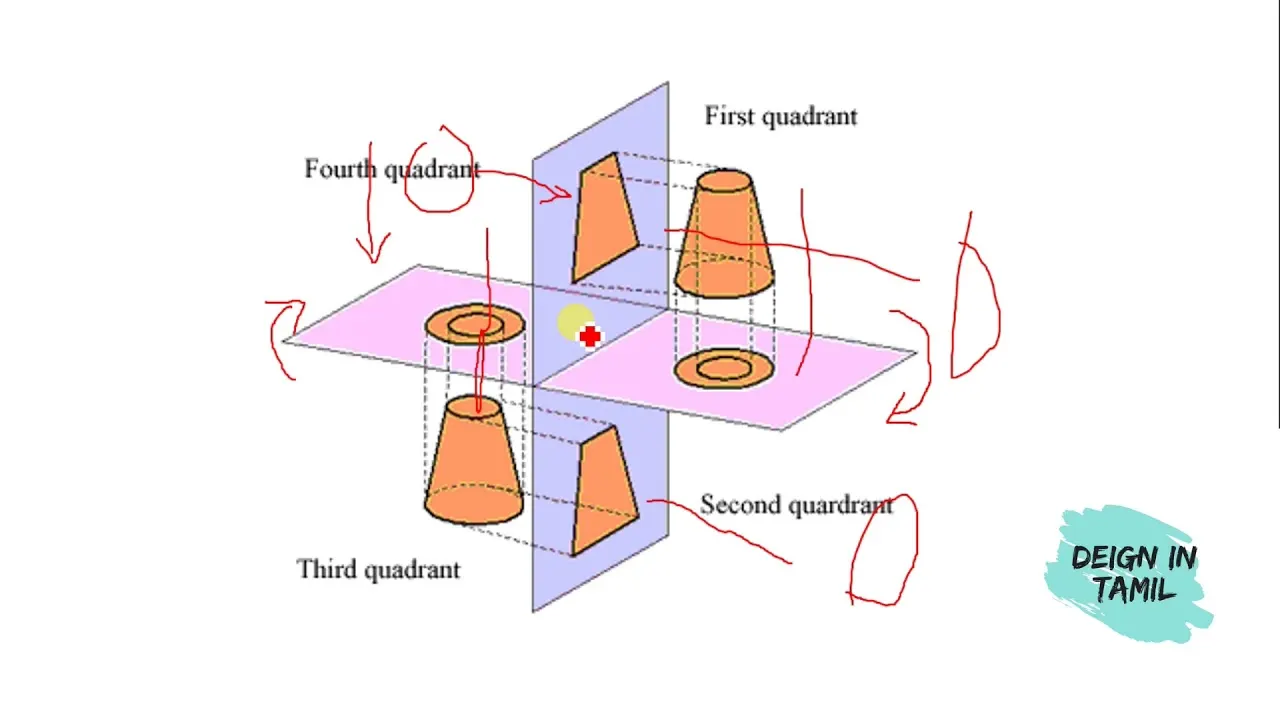
3. What is the First angle & Third angle projection? and why can't we use the 2nd and 4th angle of projection?
The orthographic projection system is used to represent a 3D object in a 2D plane. The orthographic projection system utilizes parallel lines, to project 3D object views onto a 2D plane. According to the rule of orthographic projection. To draw a projection view of a 3D object on a 2D Plane. The horizontal plane is rotated in the clockwise direction.
Types of Orthographic projection systems are first angle and third angle projection.
- First Angle Projection :
In the first angle projection, the object is placed in the 1st quadrant. The object is positioned at the front of a vertical plane and top of the horizontal plane. First angle projection is widely used in India and European countries. The object is placed between the observer and projection planes. The plane of projection is taken solid in 1st angle projection.
- Third Angle Projection :
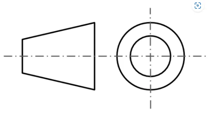
In the third angle projection, the object is placed in the third quadrant. The object is placed behind the vertical planes and bottom of the horizontal plane. Third angle projection is widely used in the United States. The projection planes come between the object and observer. The plane of projection is taken as transparent in 3rd angle projection
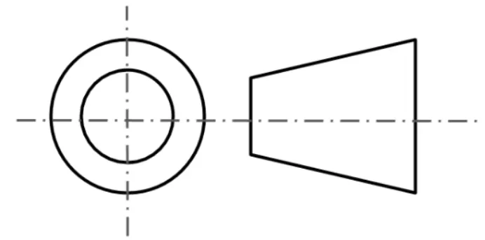
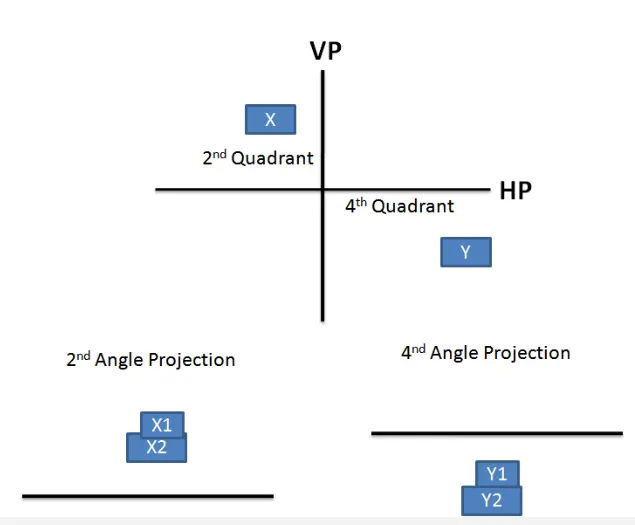
In 2nd and 4th angle projection system, the top and front views are overlap to each other. In 2nd angle projection system, the plane is in between object and observer. When we turn the adjacent plane by 90 degree to see the top view, the front and top views are overlap to each other.The same problem occurs in 4th angle of projection. The only difference is that in 4th angle of projection the object is in between the observer and plane.
4. What is GD&T? What are the benefits of GD&T?
Geometric Dimensioning and Toleraning (GD&T) is a symbolic language / representation for researching, refining and encoding the function of each feature of a part.
GD&T is a interanationoal language that is used on engineering drawing to accurately describe a part. With this designer can properly apply any geametric tolerance, they must carefully consider the fit and finction of each feature of any part.
Benfits of GD&T:
- Simple communication. GD&T allows you to convey substantial information about your part’s design using a relatively small amount of letters, numbers, and symbols. No long paragraphs of explanation necessary! The ability to communicate efficiently reduces back and forth between you and the contract manufacturing service you are working with.
- Accurate production. Since GD&T is such a precisely articulated system of language, it minimizes ambiguity in the description of a part’s design. As a result, you can be confident that your part will be manufactured with the highest degree of accuracy and work as intended in the field.
- Known tolerances. GD&T gives manufacturers a clear understanding of the tolerances for a specific part. It provides the maximum amount of tolerance for the part to function properly, which reduces part complexity so that you aren’t overspending for a minimum tolerance that you may not need.
- Universal language. You may find yourself in a situation where you want to work with a contract machining company in another country with a spoken language that is different from yours. Great news! GD&T is a universal language widely accepted across the world, thereby eliminating frustrating language barriers for overseas production.
- Precise assemblies. If you have two mating parts that need to come together in an assembly, GD&T is an excellent way to communicate how this interfacing can best take place. In these situations, GD&T clearly depicts the tolerances of each part so that manufacturers can easily tell if a measurement is off and adjust accordingly.
5. Explain all the symbols used in GD&T?
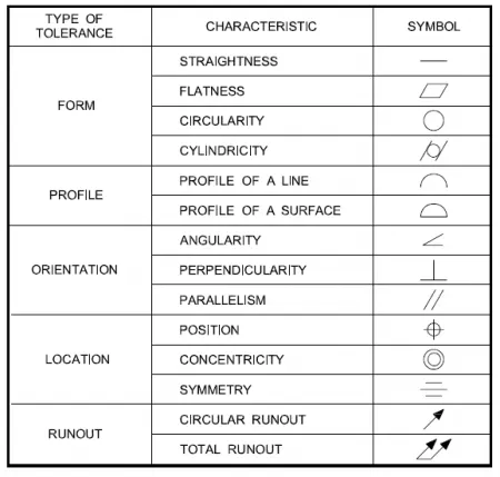
There are totally 5 groups of symbols used in GD&T as described in below table:
- Geometric Symbols
- Modifiers
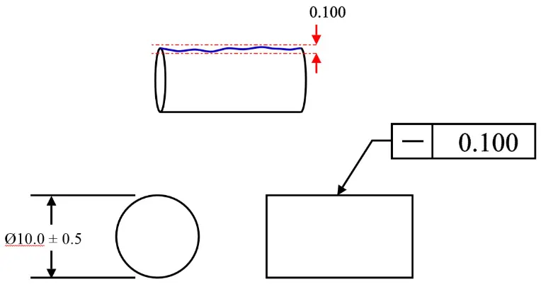
- Straightness: A condition where an element of a surface or an axis is a straight line. One of the surface elements is contrained to lie within two paallel lines seperated by the tolerance.
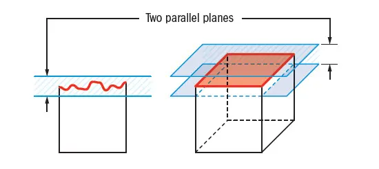
- Flatness: A 2 dimensional tolerance zone defined by two paralled lines within which the entire surface must lie.
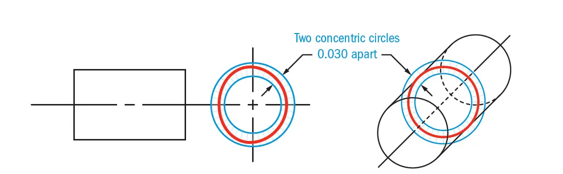
- Circularity: The condition of a surface of revolution where all the points of the surface intersected by any plane perpendicular to a common axis or passinf through a common center are equidistant from the axos of the center.
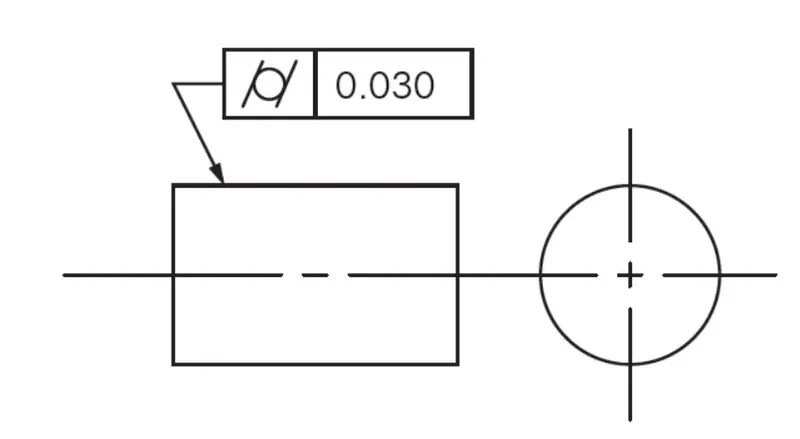
- Cylindricity: The condition of a surface of revolution in which all the points of the surface are equidistant from a common axis.
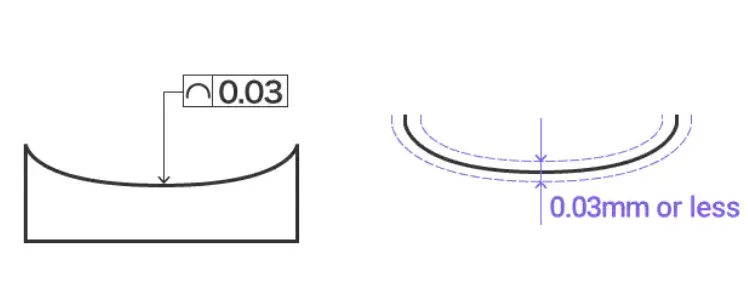
- Line profile: A uniform 2 dimensional zone limited by 2 parallel zone lines extending along the length of the feature. The amount of deviation that is allowd ifor a surface to float within the certain range while maintaining the shape or form of the each line elements that make up that surface.
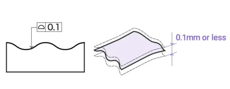
- Surface profile: It is the amount of deviation allowed for the surface.
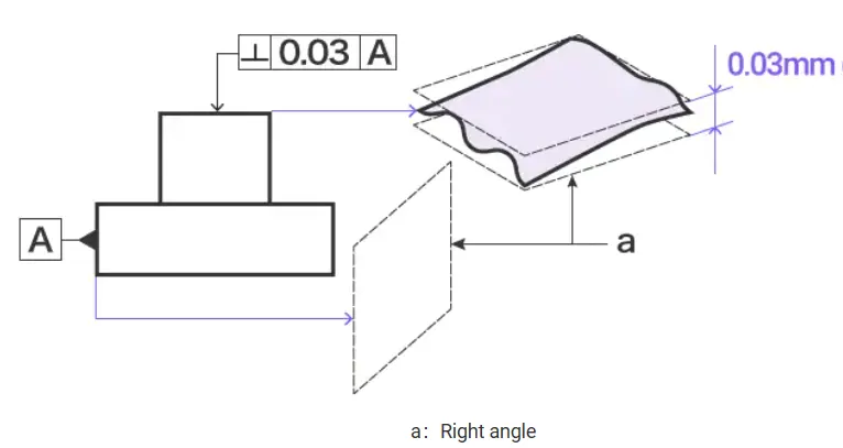
- Perpendicularity: The condition of a surface ,axis, median plane or lone which is exactly at 90 degree with respect to the dataum plane or axis.
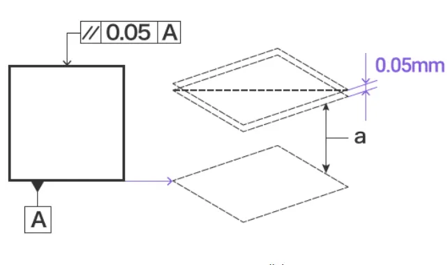
- Parallelism: The condition of a surface which is equidistant at all the points from the datum of referance. All the points of a surface must be paralled to the datum.
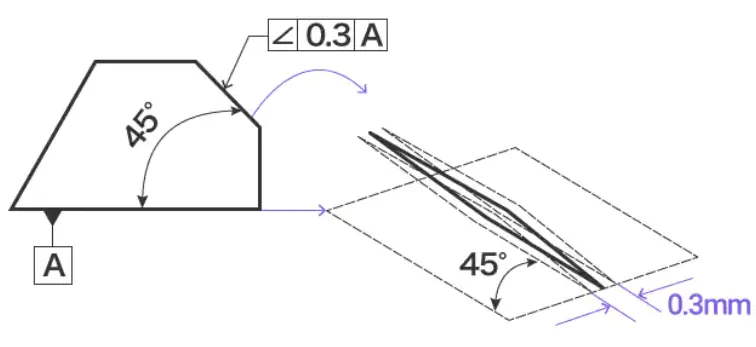
- Angularity: The distance between the 2 paralled, inclined a specified basic angle in which all the surace, or axis or center plane of a feature must lie.
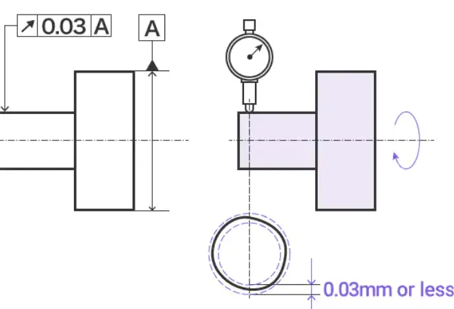
- Circular runout: A composite tolerance used to control the relationship f one or more features of a part to a datum axis dring a full 360 degree rotation about the datum axis.
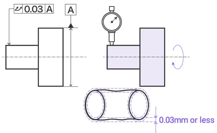
- Total runout: All surface across the entire surface of the part must be within the runout tolerances.
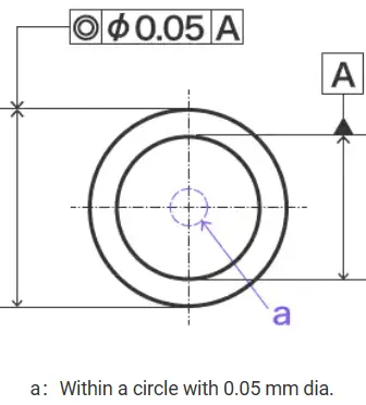
- Concentricity: It is a zone whose axis coincides with the datum axis and within which all crossectional axes of the feature being controlled must lie.
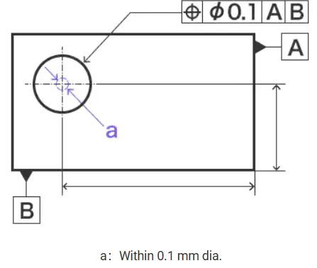
- Position: A zone within which the center axis or center plane of a feature of size is permitted to vary from its true position.
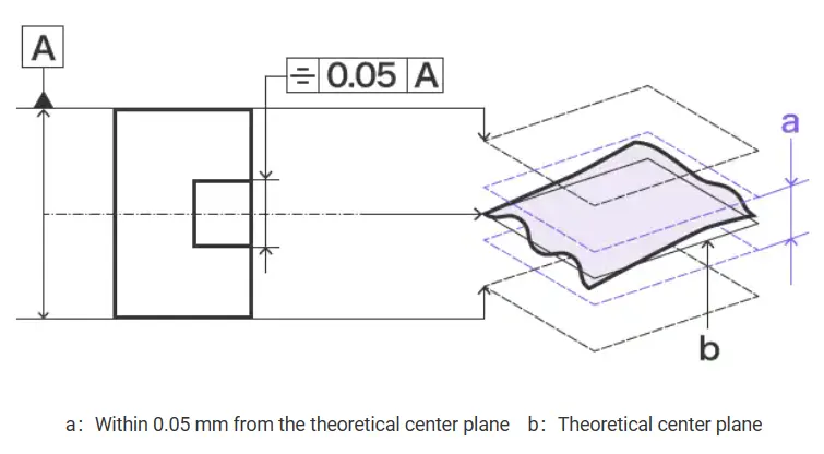
- Symmetry: It is that condition whre the median points of all opposed elements of the 2 or more feature esurfaces are congruent with axis or center plane of the datum feature.