Week 9:- 2D Detailing Challenge
1. What are the Drawing templates?
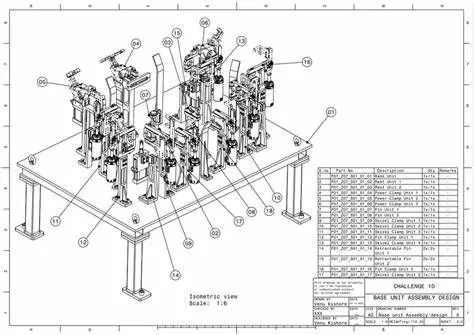
ANS:- Drawing templates are standards to be followed while detailing of any part. Drawing templates are providded by customer acoording to their standards. So every customer has its own drawing template format. Lot of details are already presents on drawing template such as material, surface treatment, machining finish, tolerances, name of assemblies, etc. As drawing templates are very useful while detailing of any part, it should be made at start of project so that detailing will be easy and save lot of time. This templates can be used as start model for different parts. Drawing templates also gives information regarding angle of projection, scaling to be used, etc. which is much needed information while manufacturing. Drawing templates contains different view to be consider for any part manufacting. It also contains unit used while drawing. Isometric and orthographic views helps while assembly of component.
2. What do you understand by Angle of projection?
ANS:- Angle of projection is representation of different orthogonal views of object. They are view formats for orthogonal view of any part or assembly. They are useful for different manufacturing operations. It is projection of 3D view on paper to obtain 2D drawing. It is like placing object in one of the quadrant and projecting its view on horizontal and vertical planes. Depending on which quadrant the object is placed we can get different angle of projection. After projecting object on planes we rotate horizontal plane in clockwice direction to get 2D view. In this way we can convert 3D object into 2D drawings.
3. What is the First angle & Third angle projection? and why can't we use the 2nd and 4th angle of projection?
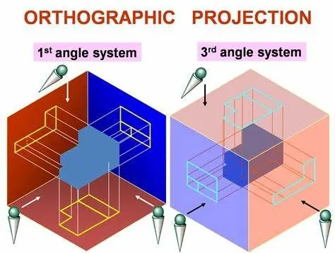
ANS:- Angle of projection is basically format for orthogonal views of parts or assemblies. When we place object in different quadrant we can get different angle of projection according to placing of object in quadrant. Basically in automative industry we use first and third angle of projection.
a. First angle projection:- In this we assume object is placed in 1st quadrant. Assumed that object is placed between the observer and vertical plane, so front view will project on vertical plane. And top view will project on horizontal plane. While projecting views it is assumed that plane of projection as non-transparent. So after rotating horizontal plane in clockwise direction, we will get top view under the font view. While LHS view will be projected on right side of front view and RHS view will be projected on left side on front view. This type of projection is widely used in India and Europe.
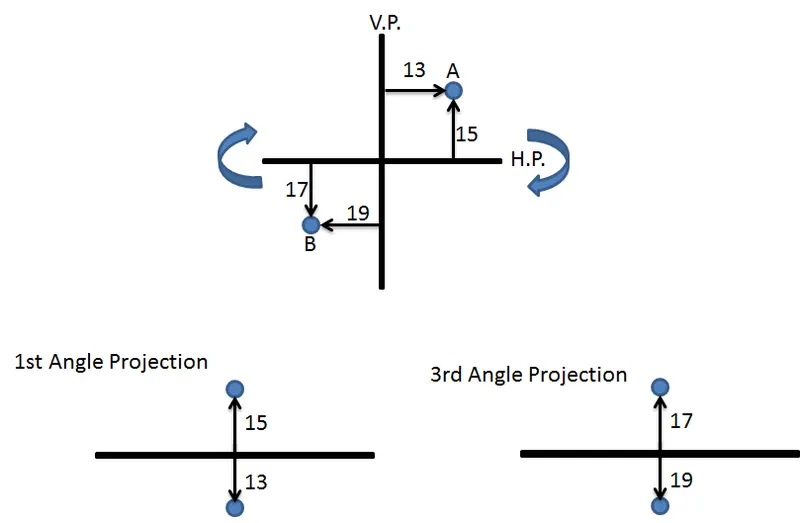
b. Third angle of projection:- In this we assume object is placed in 3rd quadrant. Assumed that vertical plane is placed between the observer and object, so front view will project on vertical plane. And top view will project on horizontal plane. While projecting views it is assumed that plane of projection as transparent. So after rotating horizontal plane in clockwise direction, we will get top view above the font view. While LHS view will be projected on left side of front view and RHS view will be projected on right side on front view. This type of projection is widely used in US and Australia.
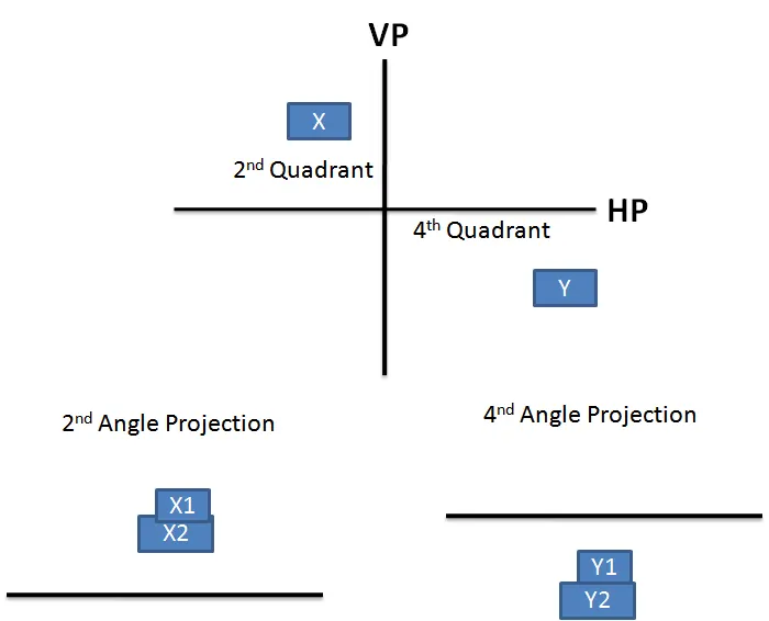
c. 2nd and 4th angle of projection:- We can project views as stated in above two sections by placing object in 2nd or 4th quadrant. But when we rotate horizontal plane in clockwise direction orthogonally it will get overlap with vertical plane. So front view and top view will overlap with each other on 2D drawing. So detailing object in 2nd and 4th quadrant is not possible. We can project point in 2nd and 4th angle of projection, but it must have different x and y co-ordinates, otherwise it will get overlap.
4. What is GD&T? What are the benefits of GD&T?
ANS:- GD&T is Geometrical Dimensioning and Tolerancing. It is language of symbols. GD&T is used by engineers and manufactures to describe product in detail. By using GD&T communication between different person operating on object will get smoother. There are total 14 symbols included in GD&T which defines different characteristics of object. All the symobols falls under three categories as follows:-
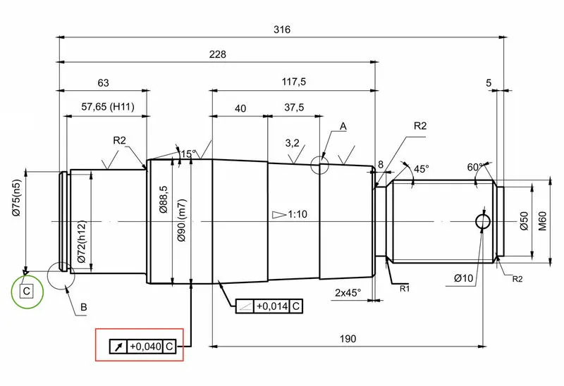
a. Form tolerance:- This type of tolerances defines shape of object. By using form tolerances we can get refinement in size of object, and it will be easy to communicate difeerent characteristics of object with related personals.
b. Orientation tolerances:- It controls the tilt of object. A reference must provided while detailing orientation tolerances. If orientation tolerances applied to surfce it will control form as well.
c. Location Tolerances:- This type of tolerances defines location and they are always associated with a basic reference line. Profile type of feature locates feature surfaces, it can control orientation and form of object.
Benefits of GD&T:-
a. Clear and precise way to communicate between customer, manufacturer and other personals envolve on same project.
b. We can calculate worst case mating limits of parts
c. Production and inspection processes are repeatable
d. A standardize designed language
e. Assembly done with qualified production parts and so chances of error is low.
5. Explain all the symbols used in GD&T?
ANS:- There are total 14 symbols use to describe different characteristics of object. All are devided into five categories as form, orientation and location tolerances. This are as follows:-
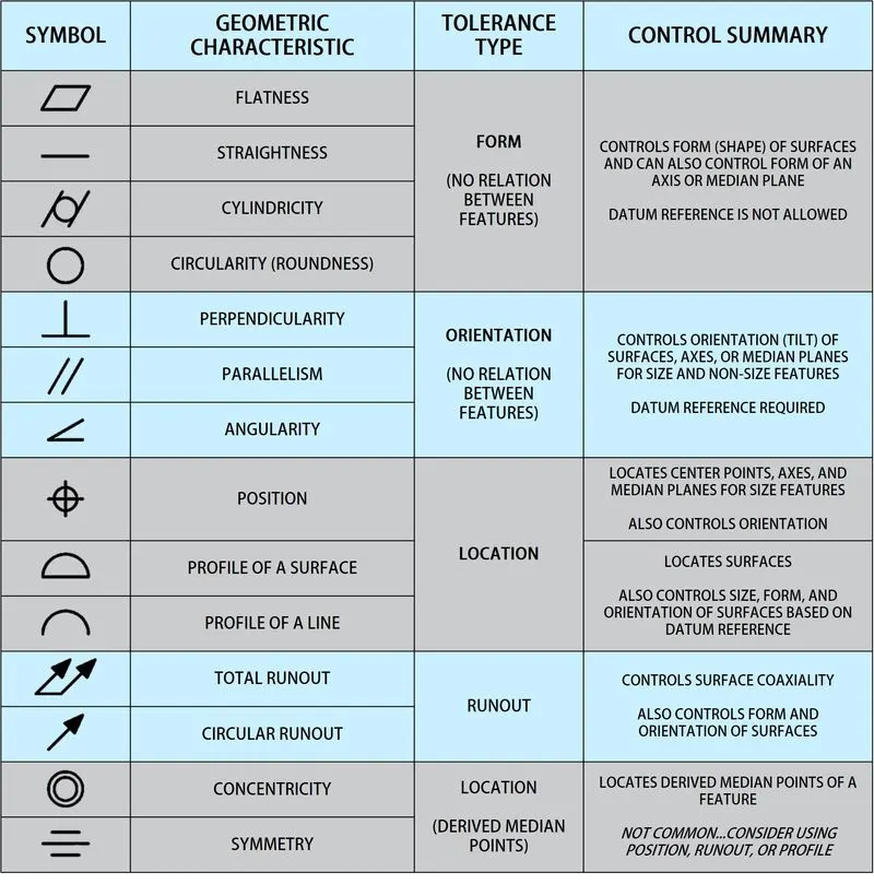
a. Form tolerances:- This controls the shape of object. It can also controls shape of axis or median plane. It can be used as refinemnt of size. It contains 4 differnt characteristics with different feature. They are as follows:-
1. Flatness:- It ensures flatness of surface. It means in which surfcae the flatness symbol is present it must be flat.
2. Straightness:- It ensures straightness of surface or line. It means in which surfcae the straightness symbol is present it must be straight.
3. Cylindricity:- It ensure cylindricity of object. It means surface must be of cylindrical shape.
4. Circularity:- It ensures circularity of object. Whenever this symbol is present on surface, it must be circular in shape.
b. Orientation Tolerances:- It controls the tilt of surface with respect to another surface. We need to mentioned angle for defining orientation of surfcae. It requires another datum surface to define feature. It can also controls form. It contains 3 different features as follows:-
1. Perppendicularity:- It defines perpendicularity os surafce or line withn respct to mentioned reference.
2. Parallelism:- It defines parallelism of two surfaces or lines with respect to mentioned datum.
3. Angularity:- It ensures angular distance from defined reference.
c. Location Tolerances:- This type of tolerances controls location of surface, axis or median plane. It is always associated with reference. It contains following 3 charcteristics:-
1. Position:- Position locates and orients the median plane and axis of feature.
2. Profile of surface:- It locates feature surface
3. Profile of line:- It locates feature line.
d. Runout:- It controls surface co-axiality. It can also controls form and orientation of surface. It has follwoing two types of features:-
1. Total runout:- It controls location, orientation and cylindricity of entire sirface.
2. Circular Runout:- It defines measurement between circular profile and datum.
e. Location (derived median points):- It locates derived median points of feature. It must have datum to define feature. It has following two types:-
1. Concentricity:- This feature ensures concentricity of circukar surface with respect to reference define.
2. Symmetry:- This tolerance defines symmetry around axis defined.