Week 9:- 2D Detailing Challenge
1. Drawing templates may be referenced when creating a new drawing. They automatically create the views, set the desired view display, create snap lines, and show model dimensions based on the template.
1. Company name
2. Project Name
3. Sheet size
4. Sheet number
5. Angle of projection
6. Revision Number/latter(if its revision drawing)
7. Signature or name of drawn by, checked by, responsible engineer and approved by
8. Parts detail
9. Quantity
10. Additional notes(Surface finish,heat treatment, material detail, etc)
11. Scale, date,unit of measurement
usually use two angle of projection in the automotive industry:
1st angle of projection
3rd angle of projection
Difference between First Angle Projection and Third Angle Projection :
| SR.NO | First Angle Projection | Third Angle Projection |
|---|---|---|
| 1 | The object is placed in the first quadrant. | The object is placed in the third quadrant. |
| 2 | The object is placed between the plane of projection and observer. | The plane of projection is placed between the object and observer. |
| 3 | The plane of projection is opaque. | The plane of projection is transparent. |
| 4 | Front view is at the top of the horizontal axis. | Front view at the bottom of the horizontal axis. |
| 5 | Top view at the bottom of the horizontal axis. | Top view at the top of horizontal axis. |
| 6 | Right view is at the left side of vertical axis. | Right view is at the right side of vertical axis. |
| 7 | Left view is at the right side of vertical axis. | Left view is at the left side of vertical axis. |
| 8 | It is widely used in Europe, India, Canada. | It is widely used in United State and Australia. |
3.
1. First Angle Projection :
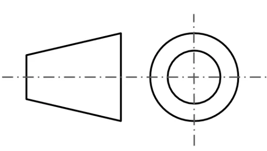
In the first angle projection, the object is placed in the 1st quadrant. The object is positioned at the front of a vertical plane and top of the horizontal plane. First angle projection is widely used in India and European countries. The object is placed between the observer and projection planes. The plane of projection is taken solid in 1st angle projection.
Symbol –
2. Third Angle Projection :
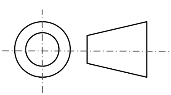
In the third angle projection, the object is placed in the third quadrant. The object is placed behind the vertical planes and bottom of the horizontal plane. Third angle projection is widely used in the United States. The projection planes come between the object and observer. The plane of projection is taken as transparent in 3rd angle projection.
Symbol –
In Engineering drawings are made either in first angle projection or in third angle projection.We do not make drawings in second or fourth angle projection.
Imagine you have Vertical Plane (VP) and Horizontal Plane (HP) (Perpendicular to each other),now we have 4 quadrants. For 1st angle projection system, we place object in 1st quadrant, for 2nd angle projection system, we place object in 2nd quadrant and so on.
In Second quadrant, Vertical plane (VP) lies in between object and observer. Therefore front view of the object will lie on vertical plane whereas top view will lie on horizontal plane. As per rule of projection when horizontal plane is rotated 90 degree in clockwise direction, top and front view will overlap. Overlapping projection views create confusion in the drawing. Therefore 2nd angle projection system is not used.
Similarly when object is placed in 4th quadrant both top and front view will overlap. Therefore fourth angle projection is also not used. To sum up, because of overlapping of front and top views 2nd and 4th angle projections are not used. First and third angle projection systems are recommended for orthographic projections
4. Geometric Dimensioning and Tolerancing (GD&T) is a design approach and manufacturing mechanism that helps engineers and designers communicate how to bring a part design to life. When documented correctly using GD&T, it is possible to build a part that exactly matches its on-paper plans.
- Datum Reference Frame (DRF): this is a 3D Cartesian coordinate system used in engineering drawings. DRF is the frame of reference and origin of all dimensions and geometric specifications on a given drawing.
- Datums: these are the points, lines, and planes that make up the DRF in drawings and are the exact anchors to which the part dimensions and tolerances are referenced. It is important to keep in mind that datums are theoretical, and therefore, perfect. For example, a datum could be a straight line on the drawing denoting a part’s flat surface.
- Datum Features: these are the features of the part such as holes. Datum features are real and tangible, and therefore, have variation. For example, a datum feature would be the part’s actual surface which is never truly flat due to small bumps from variations that occur during manufacturing, and therefore, is shown on the drawing as a straight line with a given tolerance to describe the level of variation permitted in the part’s surface straightness.
The Benefits of GD&T
GD&T offers: improved communication, increased flexibility, and enhanced quality – all 3 of which result in cost savings and improved speed to market!
- Enhanced Communication: the vital role of communication in the manufacturing process cannot be overstated. Today’s complex part designs require accurate communication across the various disciplines. The use of a single and standardized GD&T language ensures engineering, design, production, and quality teams are able to communicate clearly and accurately with each other, saving time and increasing efficiency.
- Improved Reliability and Quality: with all teams using a consistent language, GD&T avoids the misinterpretations that often occur with crowded and confusing drawing notes and instead allows for the desired dimensional and functional specifications to be achieved. Part production becomes more repeatable and consistent – simplifying inspection, reducing the part rejection rate, and improving quality.
- Increased Flexibility: as a general rule of thumb, designers should keep tolerances as large as possible while maintaining the desired functionality of the part. Manufacturers may think using GD&T results in tighter tolerances; however, GD&T actually results in more manufacturing flexibility and larger tolerances, especially for intricate or complex designs! GD&T specifies the design intent instead of the specific geometry, providing the appropriate tolerances that maximize production. For example, when GD&T data communicates functional requirements such as how the position of a hole can vary while still allowing for proper assembly, the greatest tolerance range can be utilized without impacting part function – resulting in lower design and manufacturing costs and improving quality while achieving the original design intent!
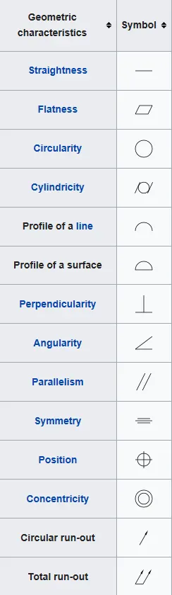
| GD&T Symbol | Control Type | Name | Summary Description |
| Form | Straightness | Controls the straightness of a feature in relation to its own perfect form | |
| Form | Flatness | Controls the flatness of a surface in relation to its own perfect form | |
| Form | Circularity | Controls the form of a revolved surface in relation to its own perfect form by independent cross sections | |
| Form | Cylindricity | Like circularity, but applies simultaneously to entire surface | |
| Profile | Profile of a Surface | Controls size and form of a feature. In addition it controls the location and orientation when a datum reference frame is used. | |
| Profile | Profile of a Line | Similar to profile of a surface, applies to cross sections of a feature | |
| Orientation | Perpendicularity | Controls the orientation of a feature which is nominally perpendicular to the primary datum of its datum reference frame | |
| Orientation | Angularity | Controls orientation of a feature at a specific angle in relation to the primary datum of its datum reference frame | |
| Orientation | Parallelism | Controls orientation of a feature which is nominally parallel to the primary datum of its datum reference frame | |
| Location | Position | Controls the location and orientation of a feature in relation to its datum reference frame | |
| Location | Concentricity | Controls concentricity of a surface of revolution to a central datum | |
| Location | Symmetry | Controls the symmetry of two surfaces about a central datum | |
| Runout | Circular runout | Controls circularity and coaxiality of each circular segment of a surface independently about a coaxial datum | |
| Runout | Total runout | Controls circularity, straightness, coaxiiality, and taper of a cylindrical surface about a coaxial datum |
|
|
Form control
As the name suggests, form control relates to the final form or shape of the feature. We define form controls to limit the deviation of the geometric tolerance from its ideal form. Some popular form control characteristics are as follows.
Straightness
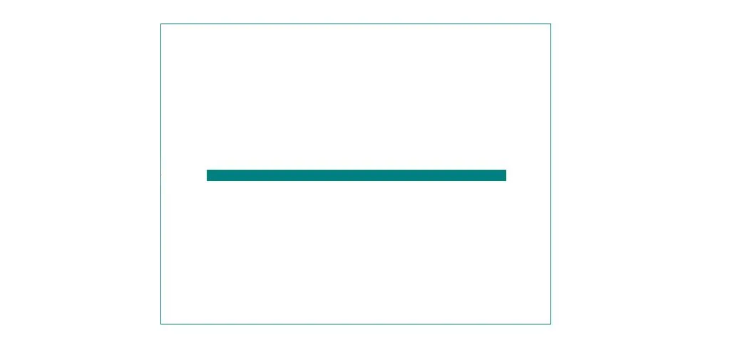
To indicate the straightness characteristic of a feature (such as an axis or a surface), we use its symbol (a straight horizontal line) in the first compartment.
Surface straightness can apply to flat surfaces like a side of a block or curved surfaces like a side of a cylinder along the direction of the axis. It defines the allowable variation of a line (2 dimensions) on the surface within a specified tolerance.
Axial straightness usually applies to the axis of a shaft or a hole, for example. Go/no go gauge is the inspection tool used in the process of making sure the part conforms to the demands.
Flatness
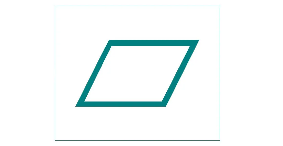
We use this characteristic for features such as the face of a part. The symbol for flatness is a parallelogram tilted to the right. The difference between the highest and lowest point of a flat surface is its flatness.
The flatness symbol does not require any datums, as it only shows a tolerance range within which the whole surface of a part must conform to in 3 dimensions.
A height gauge is used for checking the results. It touches upon different areas of the surface to determine that all the points are inside the tolerance zone.
Circularity
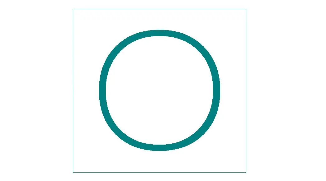
The circularity (GD&T) of a feature shows how close the circumference of the part should be to a perfect circle. It uses 2 concentric circles on a plane perpendicular to the part axis to define the suitable tolerance range in 2D. Each point of the final measurements has to fall between the circles.
This characteristic is shown as a circle in the first compartment of the feature control frame.
Cylindricity
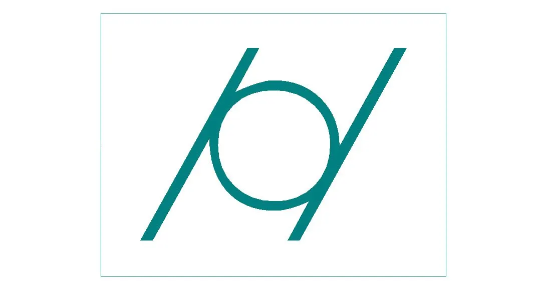
Cylindricity is basically circularity in 3D, meaning that it runs along the whole length of the part.
This feature also describes other cylindrical characteristics such as its taper, straightness, and roundness. This is why this feature is also expensive to inspect.
Profile Controls
We use profile controls to control the 3D tolerance zone around the feature. This feature helps us to give tolerance limits to advanced curves and shapes.
A feature that is good for advanced curves must naturally work well with simpler curves as well. This makes profile controls extremely versatile. This is why some designers recommend abandoning all other controls and working only with profile controls.
These controls form a tolerance limit around the advanced curve by mimicking it on both sides. It then prevents any point on the feature curve from going outside the tolerance limit. Profile controls are of two types.
Line profile
Line profile establishes a tolerance zone around varying 2D cross-sections of the part. It controls individual line elements of a part feature.
The line profile control traces the ideal curve at the tolerance limits on both sides. All points on the part’s curve must lie within these limits.
Surface profile
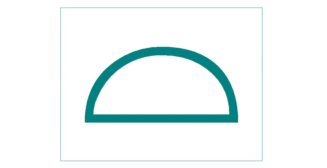
Surface profile control is more popular compared to line control. Instead of a two-dimensional tolerance zone, the surface profile control creates a 3D zone around a surface.
All points on the table’s surface must lie within the two virtual planes.
Orientation Controls
Orientation tolerance controls the orientation of a feature with respect to a defined datum. There are three types of orientation controls in GD&T.
Angularity
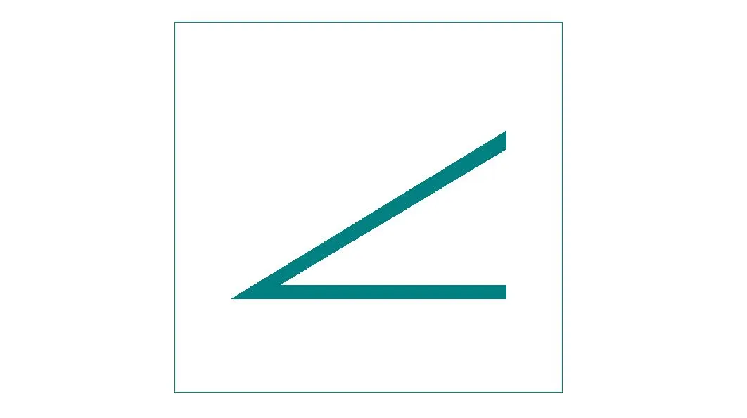
The angularity control keeps the angle of a feature with respect to the datum in check. We can use it to control a 2D line, but it is more popular with keeping surfaces (3D) under control.
This kind of tight control keeps the angle and the surface flatness in check and is recommended for part features that mate with other parts through the angled surface.
It is important to note that the angularity feature controls the angle indirectly, not being essentially the same as an angular tolerance (e.g. +/- 2°). Rather, the necessary angle is a result of keeping to the dimensional requirements laid out by this control.
Parallelism
Parallelism is a refined form of angularity. Here, the datum is the surface we need to imitate and the angle is set to 0°. There are 2 types of parallelism: surface parallelism and axis parallelism.
We can choose an axis or a surface as a reference. This becomes our datum and we reference it in the 3rd block of the feature control frame as the datum for the feature.
Similarly to angularity, it does not control the actual angle but rather secures it by laying out the requirements in the form of a tolerance zone.
Perpendicularity
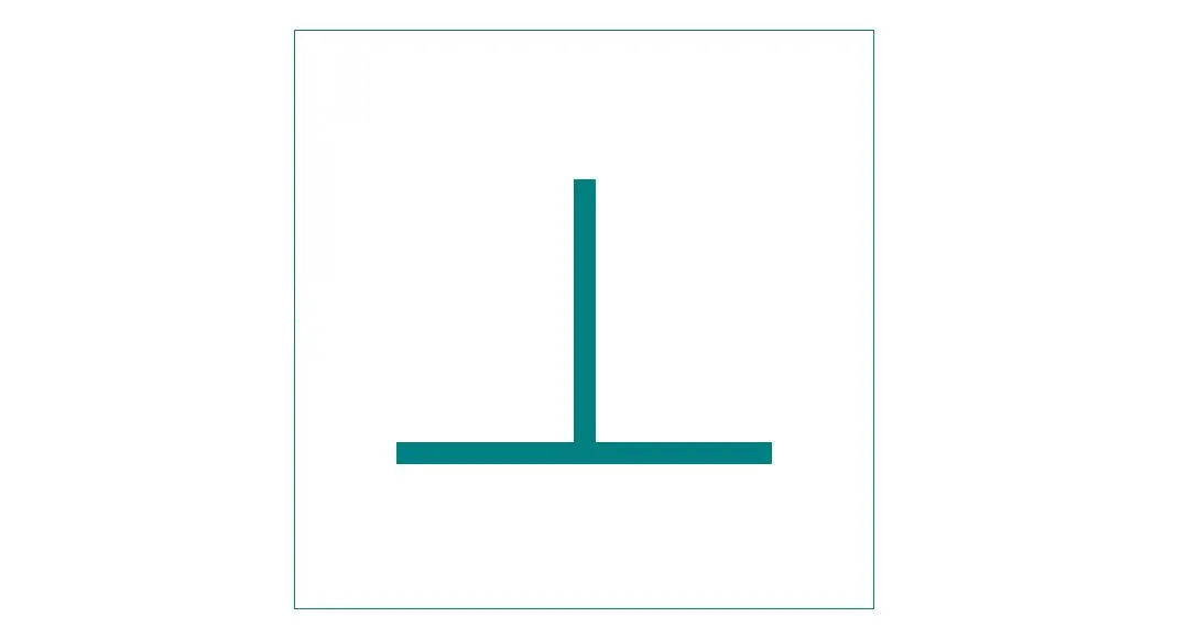
Perpendicularity is also a specific form of angularity where the angle is set to 90°. It is a tricky control since it can mean two very different types of requirements.
There’s surface perpendicularity ( Symbol:⟂), and then there’s axis perpendicularity (Symbols: ⟂+⌀).
Surface perpendicularity specifies that a surface or line needs to be perpendicular to a datum surface or line much like angularity. Two virtual planes/lines are assumed around the target surface for control.
Axis perpendicularity specifies how perpendicular an axis needs to be to the mentioned datum. This is done by erecting a virtual cylinder around the target axis on a surface exactly parallel to the datum surface.
Location Controls
The Location tolerance control is used for tight control on a feature’s position with respect to a datum. There are four main types of location controls.
Concentricity
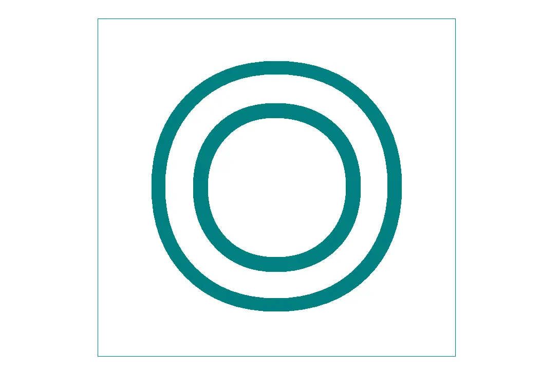
Concentricity, also known as coaxiality (even though not exactly the same thing), control maintains the concentricity of circular as well as cylindrical features.
It fixes the axis of a part to the axis of a referenced feature (datum axis). The axes of both parts are determined to be at the median points of the parts.
This control can lead to some confusion because the axes derive from outside measurements, rather than their actual placement.
Coaxiality creates a 3D tolerance zone based on surface measurements that the part must lie in.
Symmetry
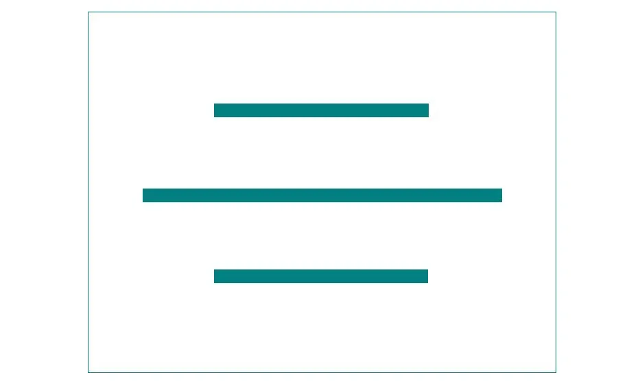
The symmetry callout establishes a central plane around which the two parts of the feature are placed at equal distance. The midpoint of the two points on either side must lie within the tolerance zone set around the central plane.
The symmetry callout is not very common. It has very limited uses and is also difficult to inspect. We need a CMM to inspect the final symmetry.
True position
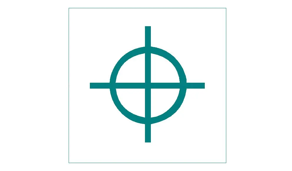
True position (popularly known as position) is a very useful callout and finds extensive use in GD&T.
Position defines how much the actual position of a feature can vary from its intended position. The definition includes the datum plane which the measurement relates to.