Photo Realistic Rendering
Modelling an American Chopper Using solidworks
OBJECTIVE: - To model an American Chopper bike using solidworks and Create rendering image using solidworks visualization.
INTRODUCTION: - This project report is about the American Chopper motorcycle. How I created the components and assembling it by using solidworks. Rendering in solidworks visualization.
SOLIDWORKS: - Version used for creating this American Chopper Bike.
- SOLIDWORKS 2021
- SOLIDWORKS VISUALIZATION
- PHOTO VIEW 360
DESIGN METHODOLOGY/APPROACH: -
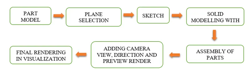
DESCRIPTION OF TOOLS AND FEATURES THAT ARE USED WHILE CREATING AMERICAN CHOPPER
- TRANSMISSION BELT: -
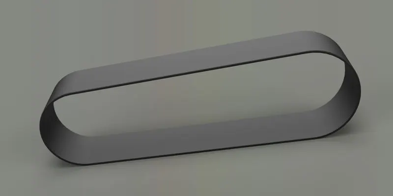
Featured used to create Transmission Belt
- Sketch
- Offset
- Boss extrude
- Fillet
- Appearance
- Sketch – The sketch is the basis for a 3D model. It can create on any plane (Front Plane, Top Plane, and Right Plane)
- Offset – Offsetentities takes a copy of your existing geometry and copies it at an offset. Instead of recreating geometry.
- Boss Extrude – It is used for convert 2D into 3D object. Moreover, Direction of extrude can be in both the directions.
- Fillet – Fillets are used to convert edges into round corners. It can used in 2D & 3D format.
- KICK STAND: -
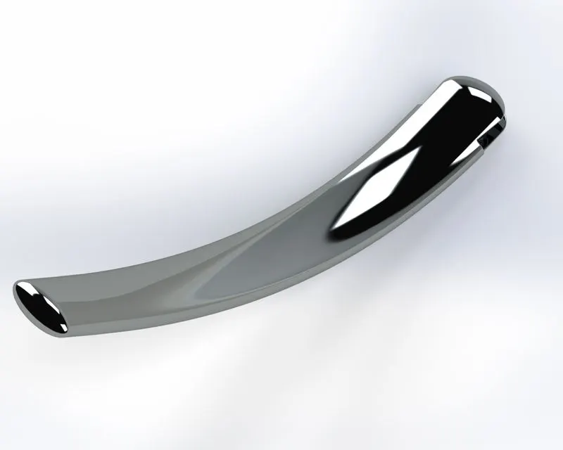
Featured used to create Kick Stand
- Sketch
- Loft
- Dome
- Cut extrude
- Split
- Boss extrude
- Fillet
- Lofted Surface - Loft Surfaces are surfaces generated by multiple 3D Curves or existing edges creating a smooth tangency between the selected curves
- Dome - It creates a dome on the curve surface of the profile.
- Extrude Cut – It used to remove material at desired shape and it also used in both the directions.
- Split Tool – This is very handy tool; when two solid bodies intersect each other, then this tool allow to delete unwanted solid body formation.
- Boss Extrude – It is used for convert 2D into 3D object. Moreover, Direction of extrude can be in both the directions.
- Fillet – Fillets are used to convert edges into round corners. It can used in 2D & 3D format.
- FRONT FENDER: -
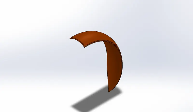
Featured used to create Front Fender
- Sketch
- Revolve
- Split
- Fillet
- Trim entities
- Revolve – It Create a sketchthat contains one or more profiles and a centerline to use as the axis around which the feature revolves.
- Trim – It is used to remove unwanted sketches from the sketch entity and also it extend the sketch entity.
- REAR FENDER: -
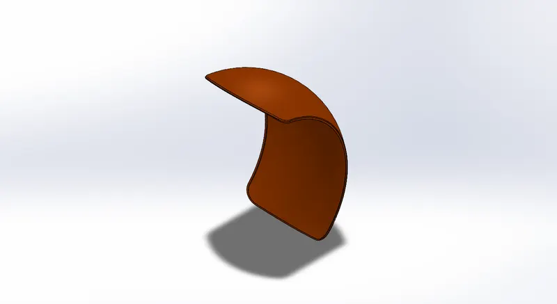
Featured used to create Rear Fender
- Sketch
- Revolve
- Split
- Fillet
- Shell
- Shell – The shell tool hollows out a part, leaves open the faces you select, and creates thin-walled features on the remaining faces
- OIL TANK: -
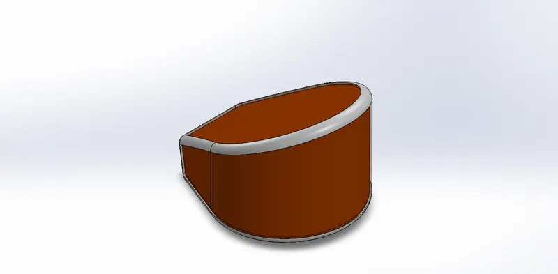
Featured used to create Oil Tank
- Sketch
- Boss extrude
- Combine
- Fillet
- Shell
- Appearance
- Combine – It is used to combine two or more different bodies intersecting to each other to make a single one body.
- Appearance – It is used to change appearance of the object and get a better look.
- CHAIN: -
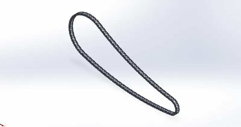
Featured used to create Chain
- Sketch
- Trim entities
- Boss extrude
- Fillet
- Blocks
- Circular Pattern
- Mirror
- Circular patter- A circular pattern is a radial array of objects around a Center point in a sketch. Axis in a partor assembly. Used to create a circular patter around the circular path reference.
- Mirror – It is used to create a copy of existing geometry or body on the preselected profile.
- Blocks – It used to save as a file link and we can used it multiple time without creating the sketch.
- PEDAL: -
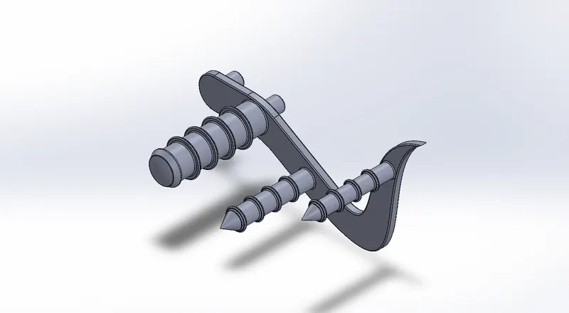
Featured used to create Pedal
- Sketch
- Boss extrude
- Fillet
- Revolve
- Dome
- Chamfer
- Linear pattern
- Revolve
- Revolve - It Create a sketchthat contains one or more profiles and a centerline to use as the axis around which the feature revolves.
- Chamfer – It used to create a flat surface on the edges.
- Linear Pattern – It used tocreate multiple instances of one or more features that you can space uniformly along one or two linear paths.
- FRONT WHEEL: -
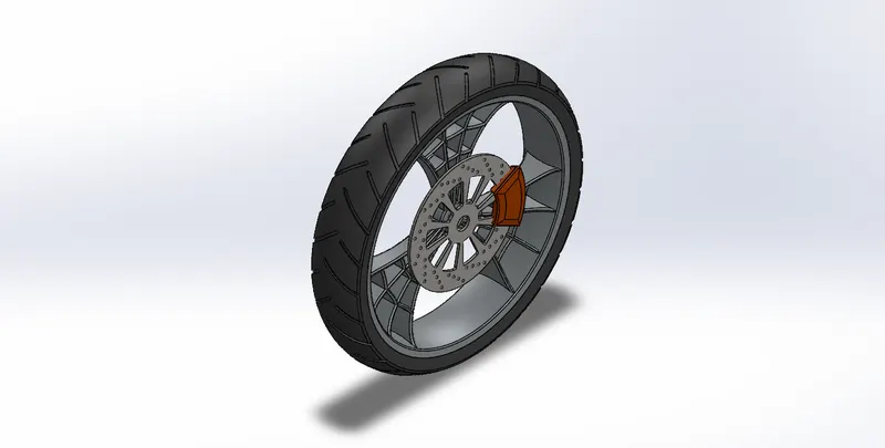
Featured used to create Front Wheel
- Revolve
- Boss extrude
- Cut extrude
- Cut revolve
- Circular pattern
- Combine
- Fillet
- Chamfer
- Cut Revolve – It used to remove material along the revolve surfaces.
- REAR WHEEL: -
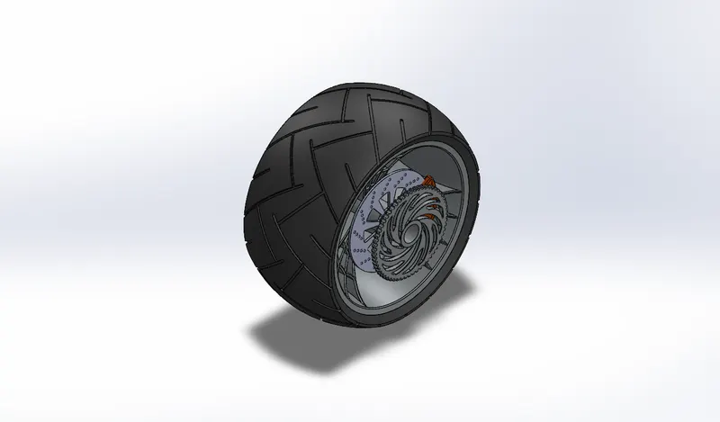
Featured used to create Rear Wheel
- Sketch
- Revolve
- Cut extrude
- Boss extrude
- Circular pattern
- Combine
- Cut revolve
- Fillet
- Chamfer
- Planes
- Planes- To create a new plane by select reference geometry then select any existing sketch. To create new plane.
- FRONT FORK: -
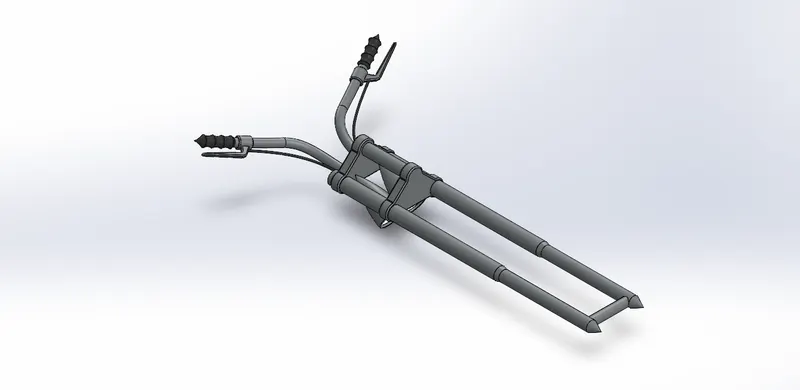
Featured used to create Front Fork
- Sketch
- Revolve
- Boss extrude
- Fillet
- Linear pattern
- Cut extrude
- Dome
- Cut revolve
- Projected curves
- Planes
- Combine
- Sweep
- Projected Curve – It is a 3D curve, which obtained by creating two or more sketches on different planes.
- Sweep – A tool create a solid or surface feature by sweeping closed loop sketch along the selected path.
- CHASSIS: -
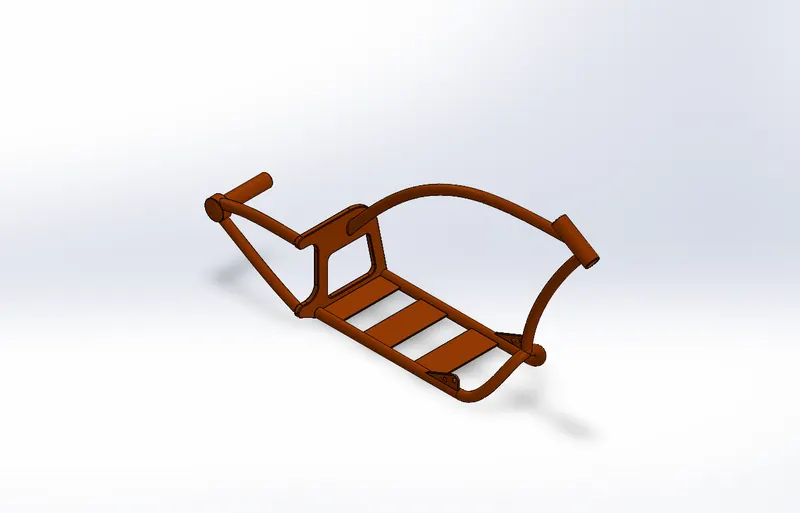
Featured used to create Chassis
- Blue print sketch
- Sketch
- Projected curve
- Sweep
- Mirror
- Boss extrude
- Cut extrude
- Chamfer
- Fillet
- Plane
- Dome
- Split
- Revolve
- Combine
- Mirror
- BLUE PRINT SKETCH – It is a reference picture used in solidworks during the sketch. It helps to make the exact model.
- ENGINE: -
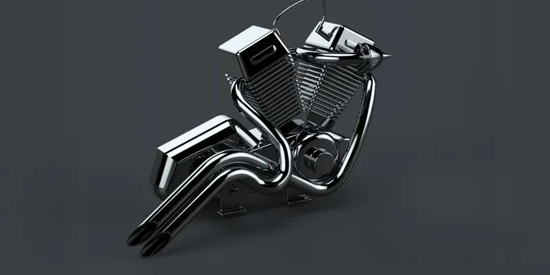
Featured used to create Chassis
- Blue print picture
- Sketch
- Boss extrude
- Fillet
- Revolve
- Plane
- Circular pattern
- Dome
- Cut extrude
- Chamfer
- Fillet
- Linear pattern
- Sweep
- Mirror
- Combine
- Curves
- Composite curve
- Split
- Circular pattern
- Composite Curve – It is a 3D curve from two different curve combining then obtained the composite curve
- GAS TANK: -
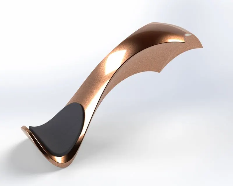
Featured used to create Chassis
- Blue print sketch picture
- Plane
- Surface sweep
- Surface trim
- Curves
- Surface loft
- Boundry surface
- Surface knit
- Mirror
- Split
- Surface extrude
- Fillet
- Cut sweep
- Shell
- Surface Loft – It used to create loft surface between two or more profiles
- Surface Trim – It used to remove material from the surfaces.
- Surface Sweep – Surface sweep are surfaces that are generated from a section curve positioned along a path.
- Surface Knit - It is a tool that can combine two or more surface into one
- ASSEMBLY: -
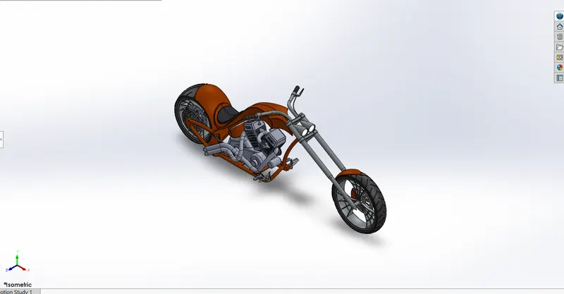
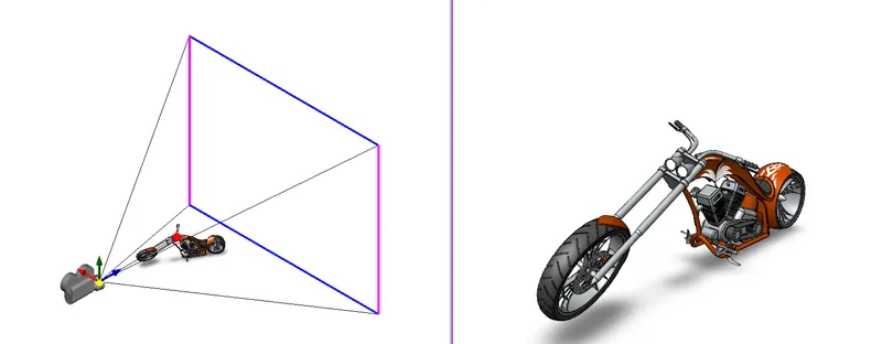
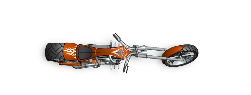
It is a process of assembly of all the components into one place. By using mate and give the perfect relations between the parts and plane. After assembling, give some decals and did some rendering and make the complete American Chopper Bike.
- ASSEMBLY: -
Front View
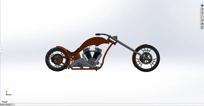
Side View
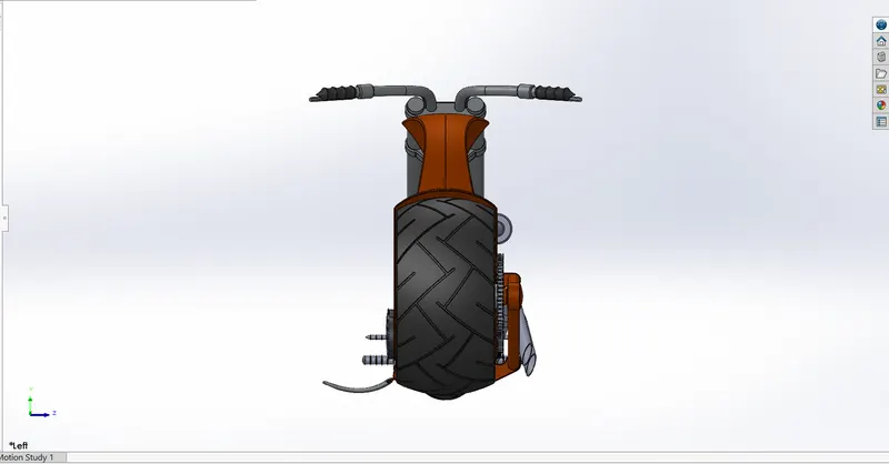
Isometric View
Camera View
Top View
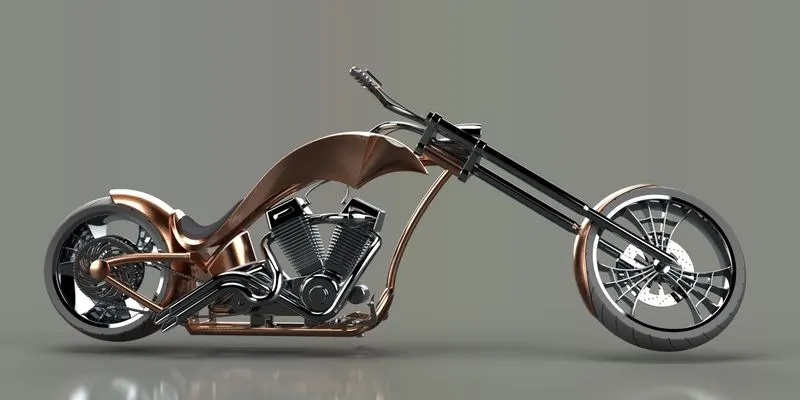
- RENDERING IMAGES OF ASSEMBLY: -
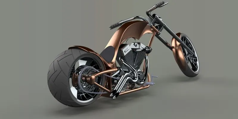
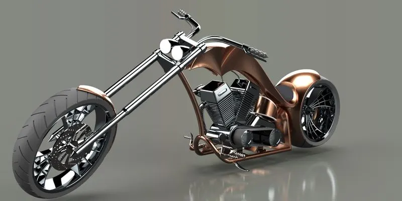
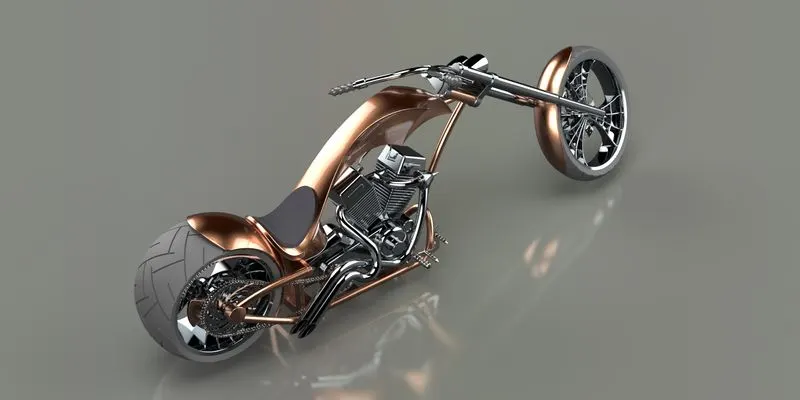
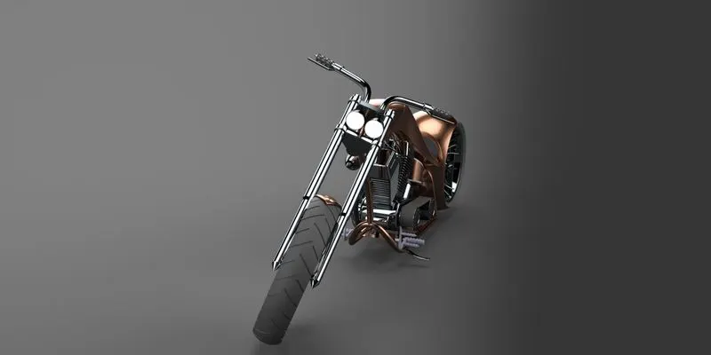
- CONCLUSION: -
- All the chopper parts are successfully modelled and assembled with fully defined relations.
- Rendering are done by using solidworks visualizations.