Week 9:- 2D Detailing Challenge
1. What are the Drawing templates?
Answer:
Engineering drawing:
- An engineering drawing is a type of technical drawing used to define the requirements for engineering products or components.
- It may also describe the process of making the item, may be used to convey engineering ideas during the design process, or may provide a record of an existing item.
Drawing Templates:
- Drawing templates are basically the drawing standards as per the customer's specifications.
- Drawing templates are a format that is used for detailing different parts/ units of the fixture.
- A drawing template file is a drawing file that has been saved with a . dwt file extension, and it specifies the styles, settings, and layouts in a drawing, including title blocks. The default drawing template files are provided as samples.
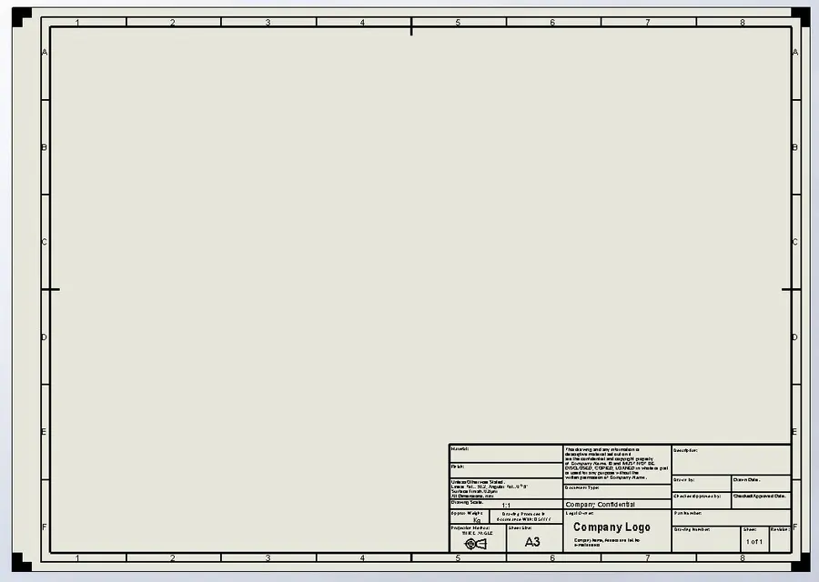
Fig shows: Drawing template
- There are 'n' numbers of details that are are already available on the template & are useful for various manufacturing processes, such as machining, finishing, tolerances, surface treatments, material, name of the parts/ unit, name of the assembly,etc.,
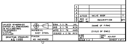
Fig shows: Title blocks of templates
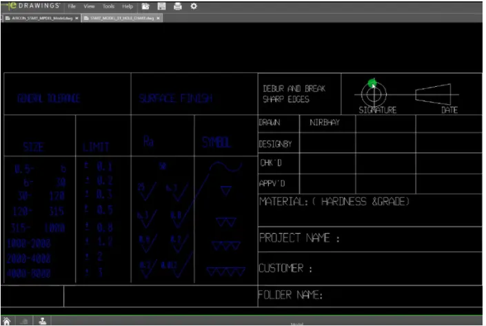
Fig shows: Title block of a template
- Preparing drawing template at the start of the project can help us save time, as these templates can be used as a starter model for detailing for different parts.
- Drawing templates also provide the information about the angle of projection to be used, views to be considered, scaling of the drawing as per the part/ unit.
- A separate template is prepared for each sheet size like A1, A2, A3, A4 & so on.
- Templates include specific layers set up with the correct layer names, color, line weights, and line styles needed. The templates also include the drawing size needed for the paper space layouts, the plot style used to plot, annotation sizes, and font styles.
- The first type is basic information that makes up a drawing but is not dependent on the drawing model, such as notes, symbols, and so forth. This information is copied from the template into the new drawing.
- The second type is instructions used to configure drawing views and the actions that are performed on that view. The instructions are used to build a new drawing with a new drawing object (model).
- The third type is parametric notes. Parametric notes are notes that update to new drawing model parameters and dimension values. The notes are re-parsed or updated when the template is instantiated.
- Company name
- Designer name
- Project name
- Sheet size
- Sheet number
- The angle of projection
- Revision number/latter (incase of revision drawing)
- signature or name of drawn by, checked by, responsible engineer and approved by.
- Parts details
- No. of quantity
- Additional notes
- Remarks
- Scale,date,unit of measurement.
- The angle at which an observer draw an object to convert it from 3D to 2D plane such as real object image to a plane paper is known as angle of projection.
- Projections are basically classified into two:
1. Perspective projection
2. Parallel projection - This is such a type of drawing in which Parallel projection is used for the preparation of the drawing of an object.
- These lines are perpendicular to the plane.
- In this drawing, it is assumed that the object is at infinity.
- The shape of an object is seen in actual size in such a drawing.
- A plane is an imaginary surface on which pictures are prepared imaginably. Then it is transferred to the paper.
- This plane is faced toward the object whose view ia to be prepared.
- Generally 3 views of an object are prepared. These are Top view, Front view and side view.
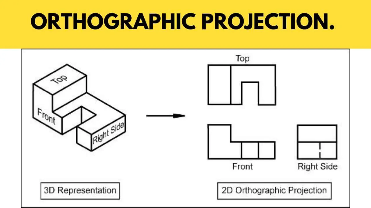
- If the plane is kept in a vertical position, then it is called the vertical plane.
- If the plane is kept in a horizontal position, then it is called the horizontal plane.
- The plane, horizontal or vertical, which are kept perpendicular to each other are called Principal Planes.These include the Frontal Plane, Profile Plane, and Horizontal Plane: In addition to this, if a plane is placed at any other place, then it is called Auxiliary plane.
- These are used to draw inclined surfaces of an object. If these are placed in such a way that they form four Quadrants, then this figure is called Dihedral angle.
- If these are placed in such a way that they form eight quadrants, then this figure is called Trihedral angle.
- If the first Quadrant is used to draw the projections, then this system is called First Angle System.
- If the third quadrant is used, then this system is called the Third Angle System.
- In the First Angle System, the top view is placed below while the front view is upward and the side view is by the side of the front view.
- In the Third Angle System, the top view is upward while the front view is downward and the side view is towards, aside from the front view.
Views of Orthographic Projection.
Following views are formed of an object in Orthographic Projection.
1. Front View.
2. Top View.
3. Back View.
4. Bottom View.
5. Right Side View.
6. Left Side View.
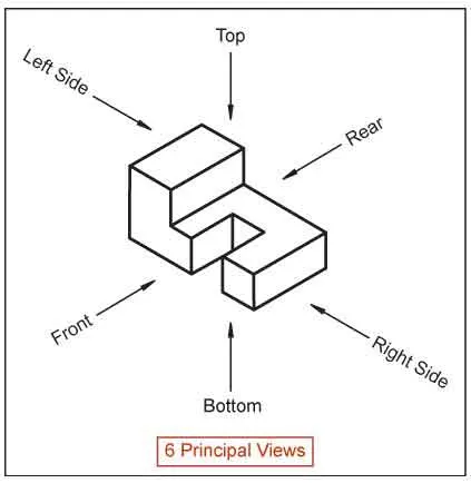
Generally, the Following Three views are prepared in the orthographic drawing.
1. Front View:
This view is prepared by placing the object in front. The length and height of an object are shown in this view.
2. Top View:
This view is prepared by looking to the object from the upper side. The length and breadth of the object are shown in it.
3. Side View:
This view is prepared by looking to the object from the right side or left side. The breadth and height of the object are shown in it.
Principal Plane.
A plane is an imaginary and invisible clear surface. The drawing constructed on this imaginary curtain is transferred on the drawing sheet.
However, the plane placed in the following positions is called the Principal Plane. Besides such positions, the plane will be called Auxiliary Plane.
1. Frontal Plane.
2. Profile Plane.
3. Horizontal Plane.
1. Frontal Plane.
Such a plane which is placed in front of an object, while projections are drawn, is called the Frontal plane.
2. Profile Plane.
Such a plane which is placed to the right or left of an object. Side view of the object is drawn on this plane.
3. Horizontal Plane.
This is a plane which is placed upward or downward in the horizontal position of an object. Top view of the object is constructed on this plane.
Drawing of Orthographic Projection.
For drawing Orthographic Projection, different planes are placed in a particular order.
Then a specific view is drawn through every plane.
A plane is placed in the following two Methods.
1. Dihedral Angle.
2. Trihedral Angle.
1. Dihedral Angle.
In this method, two principal planes are kept perpendicular to each other. One of these planes is Frontal, while other is horizontal.
Four right angles are obtained in this way which is called Dihedral Angle.
Each right angle is called a quadrant. The object is placed in any of these right angles to take orthographic projection.
The front view is taken on the frontal plane, and the top view is taken on the horizontal plane.
Profile plane is used to take side views.
This plane is held perpendicular at the ends of the other two planes.
2. Trihedral Angle.
In this method, all the three Principal planes are taken perpendicular to one another, and eight right angles are formed.
Thus, these are called Trihedral angle.
Each right angle is called an Octant. An object is placed in any of these right angles to take orthographic projection.
The front view is taken on the frontal plane, and the top view is taken on the horizontal plane. Profile plane is used to take side views.
Rules of Orthographic Drawing.
Following rules should be followed while forming orthographic drawing.
1. Front view and top view always form over/under each other.
2. The front view shows the length and height of an object.
3. The side view shows the breadth and height of an object.
4. The top view shows the length and breadth of an object.
5. Side view always forms beside the front view.
6. Projection line always forms by the meeting of two surfaces.
7. The hidden detail of an object is always shown by dotted line.
Selection of View.
Following points should be kept in mind at the selection of view,
1. The more detailed view should be selected.
2. The selection of view with maximum detail should be made.
3. The selection of view with more internal details should be made.
4. The selection of view of required details should be made.
3. What is the First angle & Third angle projection? and why cant we use the 2nd and 4th angle projection?
Answer:
The orthographic projection system is used to represent a 3D object in a 2D plane. The orthographic projection system utilizes parallel lines, to project 3D object views onto a 2D plane.
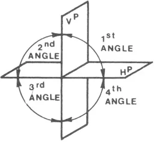
According to the rule of orthographic projection. To draw a projection view of a 3D object on a 2D Plane, The horizontal plane is rotated in the clockwise direction.
Types of Orthographic projection systems are first angle and third angle projection.
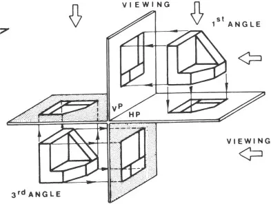
1. First Angle Projection :
In the first angle projection, the object is placed in the 1st quadrant. The object is positioned at the front of a vertical plane and top of the horizontal plane. First angle projection is widely used in India and European countries. The object is placed between the observer and projection planes. The plane of projection is taken solid in 1st angle projection.
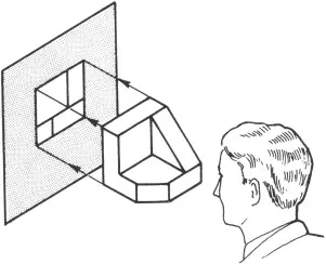
Symbol –
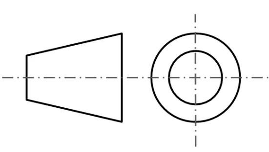
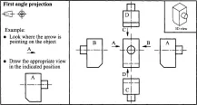
Characteristics of First Angle Projection:
1. Front view always comes over the top view.
2. Top view always comes under the front view.
3. Right side view always comes to the left at the front view.
4. Left side view always comes to the right of the front view.
5. The view is always in opposite direction to the observer.
6. The object is always in the middle of the view and the observer.
2. Third Angle Projection :
In the third angle projection, the object is placed in the third quadrant. The object is placed behind the vertical planes and bottom of the horizontal plane. Third angle projection is widely used in the United States. The projection planes come between the object and observer. The plane of projection is taken as transparent in 3rd angle projection.
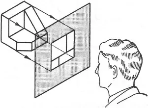
Symbol –
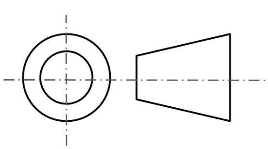
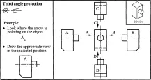
Characteristics of Third Angle Projection:
1. Top view always comes over the Front view.
2. Front view always comes under the top view.
3. Right side view always comes to the right of the front view.
4. Left side view always comes to the left of the front view.
5. The view is always formed to the side of the observer.
6. The view is always in the middle of the object and the observer.
Difference between First Angle Projection and Third Angle Projection :
| SR.NO | First Angle Projection | Third Angle Projection |
|---|---|---|
| 1 | The object is placed in the first quadrant. | The object is placed in the third quadrant. |
| 2 | The object is placed between the plane of projection and observer. | The plane of projection is placed between the object and observer. |
| 3 | The plane of projection is opaque. | The plane of projection is transparent. |
| 4 | Front view is at the top of the horizontal axis. | Front view at the bottom of the horizontal axis. |
| 5 | Top view at the bottom of the horizontal axis. | Top view at the top of horizontal axis. |
| 6 | Right view is at the left side of vertical axis. | Right view is at the right side of vertical axis. |
| 7 | Left view is at the right side of vertical axis. | Left view is at the left side of vertical axis. |
| 8 | It is widely used in Europe, India, Canada. | It is widely used in United State and Australia. |
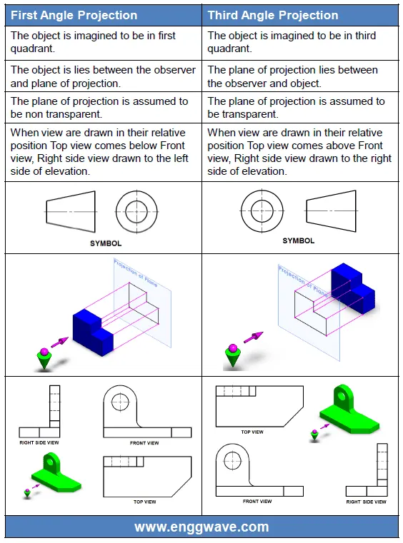
Fig shows: Difference between First angle and Third angle projection
Reason for not using 2nd and 4th angle projection:
- In practice only first angle quadrant and the third angle quadrant are used since these are pure views. The second angle quadrant and fourth angle quadrant are combination of first and third angle projections and cause confusion to the reader.
- 2nd and 4th angle of projection systems are not used because of the limitation of overlapping.
How orthographic projection system works?
- Let's consider a point A & B in the 1st and 3rd quadrant respectively. As per rule of orthographic projection, to bring drawing views from 3D to 2D planes, Horizontal plane (HP) is rotated in the clockwise direction.
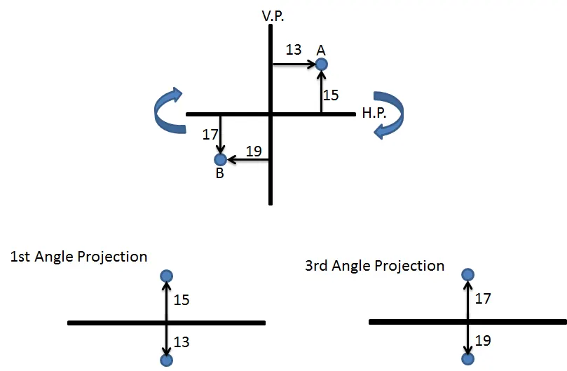
- As shown in the above image, point A in the 1st quadrant lies in between the observer and projection plane. Therefore, Front view of point A will be in a vertical plane(VP) and the top view will be on the horizontal plane (HP).
- Similarly, point B in the 3rd quadrant can be projected on the horizontal and vertical plane.
To understand why the 2nd and 4th angle projection systems are not used , we will repeat the above experiment in the 2nd and 4th quadrant.

- Lets consider rectangular parts X & Y are placed in the 2nd and 4th quadrant respectively.
- In the 2nd quadrant, the vertical plane (VP) lies in between object X and the observer. Therefore, the front view of the object X will lie on a vertical plane whereas the top view will lie on a horizontal plane. As per the rule of projection when a horizontal plane is rotated 90 degrees in a clockwise direction, the Top and front views will overlap.
- Overlapping projection views create confusion in the drawing. Therefore the 2nd angle projection system is not used.
- The same thing happens when the object is placed in the 4th quadrant. Both the top and front view overlap.
- Hence because of overlapping of front and top views 2nd and 4th angle of projections are not used.
4. What is GD&T ? What are the Benefits of GD&T?
Answer:
- A design model is an idealized representation of a part design. However, the design model by itself does not fully define the design. Due to imperfections in manufacturing and inspection processes, physical parts never match the design model exactly. An important aspect of a design is to specify the amount the part features may deviate from their theoretically exact geometry.
- Geometric dimensioning and tolerancing, often referred to as GD&T, is a symbolic language used on engineering drawings and models to define the allowable deviation of feature geometry.
- The language of GD&T consists of dimensions, tolerances, symbols, definitions, rules, and conventions that can be used to precisely communicate the functional requirements for the location, orientation, size, and form of each feature of the design model.
- Thus, GD&T is an exact language that enables designers to “say what they mean” with regard to their design models. Production can then use the language to understand the design intent and inspection looks to the language to determine set up requirements.
- Dimensioning specifications define the nominal, as-modeled or as-intended geometry. One example is a basic dimension.
- Tolerancing specifications define the allowable variation for the form and possibly the size of individual features, and the allowable variation in orientation and location between features.
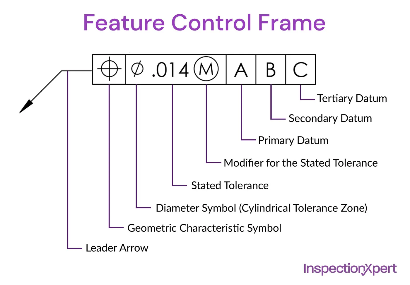
There are some fundamental rules that need to be applied:
- All dimensions must have a tolerance. Every feature on every manufactured part is subject to variation, therefore, the limits of allowable variation must be specified. Plus and minus tolerances may be applied directly to dimensions or applied from a general tolerance block or general note. For basic dimensions, geometric tolerances are indirectly applied in a related Feature Control Frame. The only exceptions are for dimensions marked as minimum, maximum, stock or reference.
- Dimensions define the nominal geometry and allowable variation. Measurement and scaling of the drawing is not allowed except in certain cases.
- Engineering drawings define the requirements of finished (complete) parts. Every dimension and tolerance required to define the finished part shall be shown on the drawing. If additional dimensions would be helpful, but are not required, they may be marked as reference.
- Dimensions should be applied to features and arranged in such a way as to represent the function of the features. Additionally, dimensions should not be subject to more than one interpretation.
- Descriptions of manufacturing methods should be avoided. The geometry should be described without explicitly defining the method of manufacture.
- If certain sizes are required during manufacturing but are not required in the final geometry (due to shrinkage or other causes) they should be marked as non-mandatory.
- All dimension and tolerance should be arranged for maximum readability and should be applied to visible lines in true profiles.
- When geometry is normally controlled by gage sizes or by code (e.g. stock materials), the dimension(s) shall be included with the Gage or code number in parentheses following or below the dimension.
- Angles of 90° are assumed when lines (including center lines) are shown at right angles, but no angular dimension is explicitly shown. (This also applies to other orthogonal angles of 0°, 180°, 270°, etc.)
- Dimensions and tolerances are valid at 20 °C (68 °F) and 101.3 kPa (14.69 psi) unless stated otherwise.
- Unless explicitly stated, all dimensions and tolerances are only valid when the item is in a free state.
- Dimensions and tolerances apply to the length, width, and depth of a feature including form variation.
- Dimensions and tolerances only apply at the level of the drawing where they are specified. It is not mandatory that they apply at other drawing levels, unless the specifications are repeated on the higher level drawing(s).
Benefits of GD&T:
- Saving Money — GD&T enhances design accuracy by allowing for appropriate tolerances that maximize production. For many projects, the process provides extra or bonus tolerances, further increasing cost effectiveness.
- Ensuring Dimensional and Tolerance Requirements — By explicitly stating all design requirements, a thorough GD&T process guarantees accurate fulfillment of all dimensional and tolerance specifications.
- Assisting Digital Design Methods — Clear, concise GD&T data is readily adaptable to digital design programs, including nearly universally used 2D and 3D CAD files.
- Offering Uniformity and Convenience — As a single, consistent language, GD&T reduces guesswork and interpretation while ensuring consistent geometries across design and manufacturing.
- Providing Accurate Communication — Today’s intricate designs demand the most accurate and reliable communication. GD&T enables designers, manufacturers, and inspectors to communicate clearly with one other, saving time and making the process more efficient.
5. Explain all the symbols used in GD&T?
Answer:
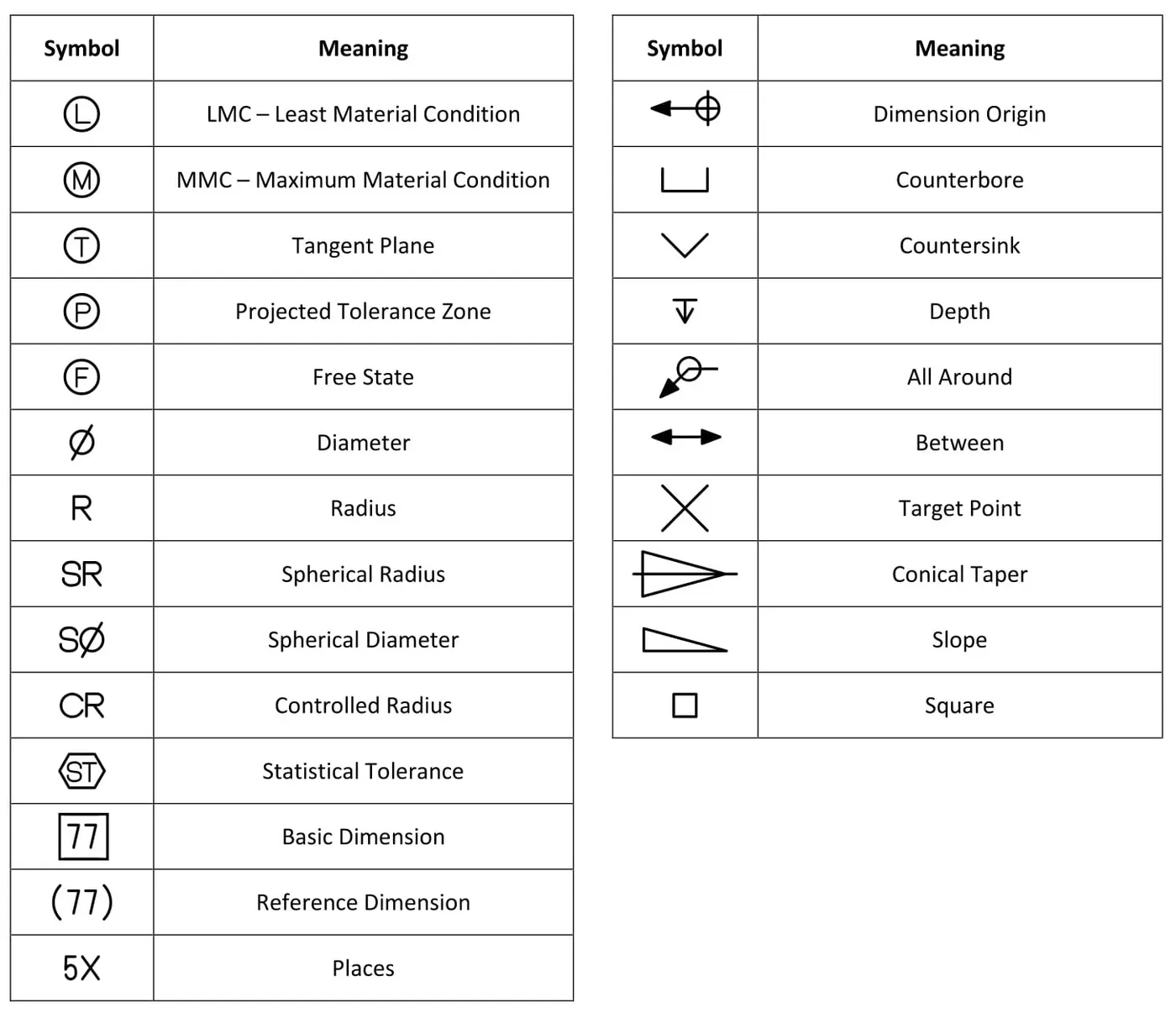
Symbols usedd in GD&T:
GD&T has 14 symbols out of which 10 are the most commonly used features. They are categorized based on a form, orientation, location, profile and run out.
1. Form:
a. Straightness:
The straightness requirement specifies how perfectly straight a target should be. It is applied to lines and not planes, and represents a curve in the center line or generatrix. Therefore, straightness is used to indicate the warpage tolerance of long objects.
For example-
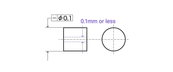
If a tolerance frame is connected to the size indicating the diameter of a cylinder, the axis of that cylinder must be within a cylinder with a diameter of 0.1 mm.
b. Flatness:
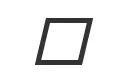
The flatness requirement specifies the evenness of a surface, or how accurately flat a target plane should be. The most protruding part and the most concaved part must be at a specific distance between two planes that are separated vertically.
For example-
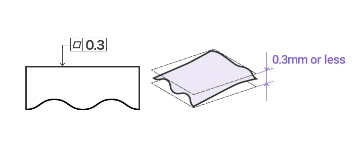
This surface must be between two parallel planes separated by only 0.3 mm.
c. Roundness:

The roundness requirement specifies how perfectly circular a target—the circular cross-section of a shaft, bore, or cone—should be.
For example-
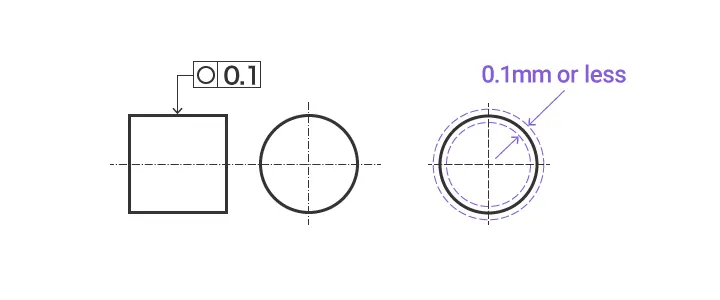
The outer circumference of any cross-section of a shaft cut perpendicularly should be between two concentric circles just 0.1 mm apart on the same plane.
d. Cylindricity:

The cylindricity requirement specifies how accurately circular and straight a target cylinder is. The value represents any distortion in a cylinder.
For example-
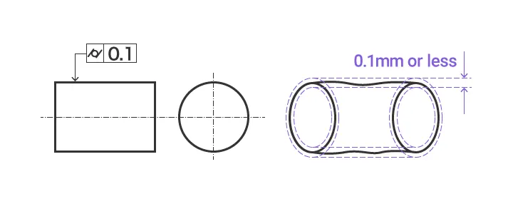
The target plane must be between two coaxial cylinders just 0.1 mm apart.
2. Orientation:
a. Parallelism:
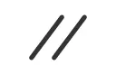
While it appears to be similar to flatness, parallelism involves a datum (reference plane or line).
The parallelism requirement specifies that two lines or planes are parallel.
For example-
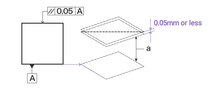
The plane indicated by the indication arrow must be parallel to datum plane A and be between two planes only 0.05 mm apart in the direction of the indication arrows.
b. Perpendicularity:
The perpendicularity requirement specifies the accuracy of how perpendicular a target is to the datum (reference plane or line).
Instead of degrees, millimeters are used as the unit for the value of perpendicularity indication.
For example-
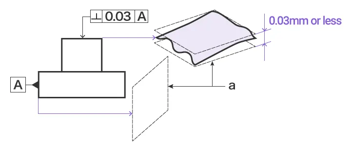
The plane indicated by the indication arrow must be within two parallel planes perpendicular to datum plane A and with a diameter of 0.03 mm.
c. Angularity:
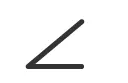
The angularity requirement specifies how accurate an angle is to the datum (reference plane or line) when the specified line or plane is not 90 degrees.
Instead of degrees, the millimeter is used as the unit for the value of angularity indication.
For example-
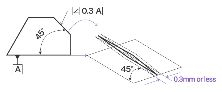
The plane indicated by the indication arrow must be theoretically exactly angled by 45 degrees to the datum plane A and between two parallel planes only 0.3 mm apart in the direction of the indication arrows.
3. Location:
a. True position:
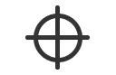
The true position requirement specifies the accuracy of the position in relation to the datum (reference plane or line).
For example-
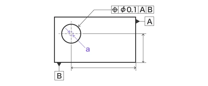
The center of the circle indicated by the indication arrow must be within a circle with a diameter of 0.1 mm.
b. Concentricity:

The concentricity requirement specifies the accuracy of concentricity of the axes of two cylinders (no deviation of the center).
For example-
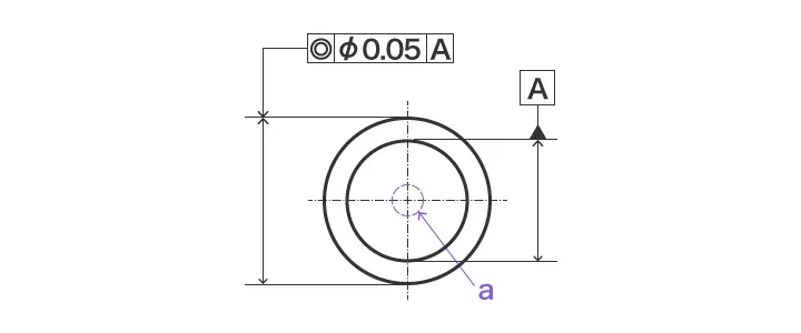
The axis of the cylinder indicated by the indication arrow must be within a cylinder with datum axis line A as the axis and a diameter of 0.05 mm.
c. Symmetry:
The symmetry requirement specifies the accuracy of how symmetrical a target is to the datum (reference plane).
For example-
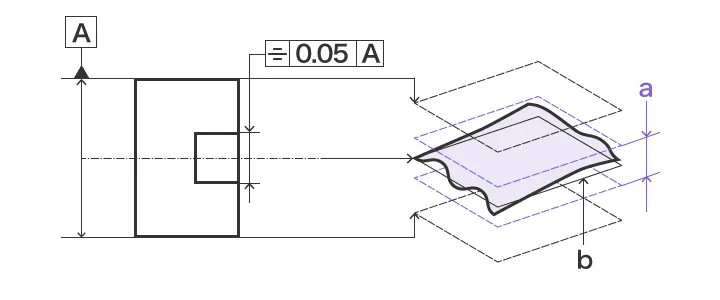
The center plane indicated by the indication arrow must be between two parallel planes symmetrical to the datum center plane A and separated from each other by 0.05 mm.
4. Runout:
a. Circular runout:
Circular run-out specifies the run-out of any part of a circumference when a part is rotated.
To meet the circular run-out requirement, the run-out of the measured value when the part is rotated must be within the specified range.
For example-
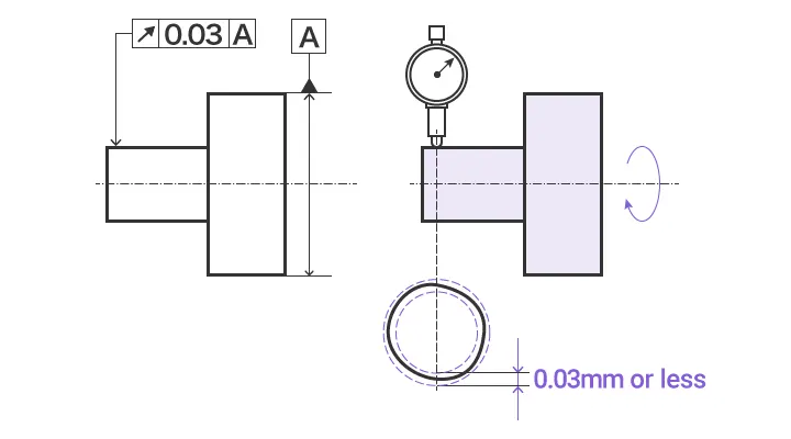
The run-out of the cylindrical surface in the radial direction, indicated by the indication arrow, must not surpass 0.03 mm on any measurement plane perpendicular to the datum axis line when the target is rotated once on the datum axis line.
b. Total runout:
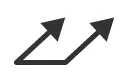
Total run-out specifies the run-out of the entire surface of a part when it is rotated.
To meet the total run-out requirement, the run-out of the measured value of the entire cylinder surface must be within the specified range.
For example-
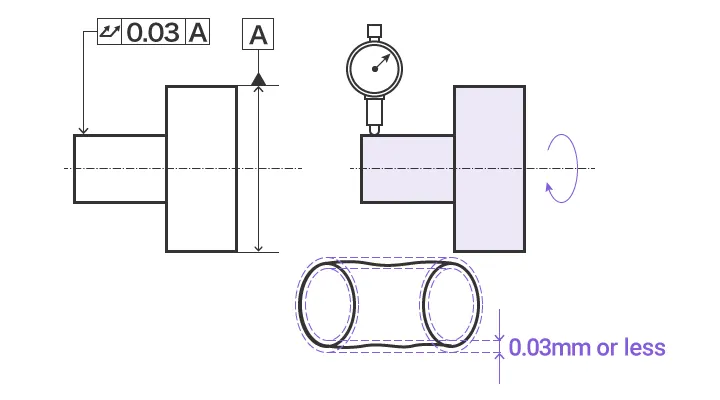
The total run-out of the cylindrical surface in the radial direction, indicated by the indication arrow, must not surpass 0.03 mm at any point on the cylindrical surface when the cylinder part is rotated on the datum axis line.
5. Profile:
a. Profile of a line:
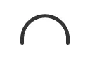
The profile of the line requirement indicates whether the curvature of a designed part is made to its design. The value indicates any distortion in the profile line (line element that appears on the cross-section of a surface). The cross-section line cutting across the specified curvature must be within the tolerance zone.
For example-
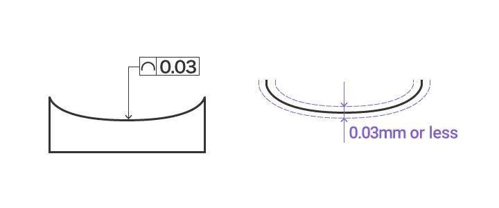
The target profile on any cross-section parallel to the projection plane must be between the two envelopes created by a circle with a diameter of 0.03 mm and a center on the line having a theoretically exact profile.
b. Profile of a plane:

The profile of the plane requirement indicates whether the curvature (surface) of a designed part is made to its design.
Unlike the profile tolerance of a line, the profile tolerance of the plane involves the entire specified curvature.
For example-
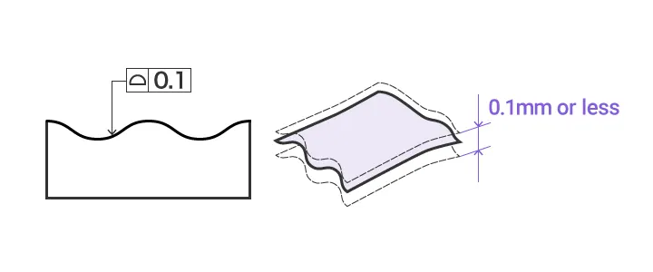
The target plane must be between two envelope planes created by a sphere with a diameter of 0.1 mm and a center on the plane having a theoretically exact profile.
Other GD&T symbols that are used are: