Week 5:- Rest Unit & Clamp Unit Design Challenge
PROJECT TITLE - Design of clamp units and rest units.
OBJECTIVE
- To understand and design 3 different types of Power Clamp Unit with different Riser, Blade and Clamp Arm for the given Car Panel.
- To understand and design 2 different types of Rest Unit for the given Car Panel.
INTRODUCTION
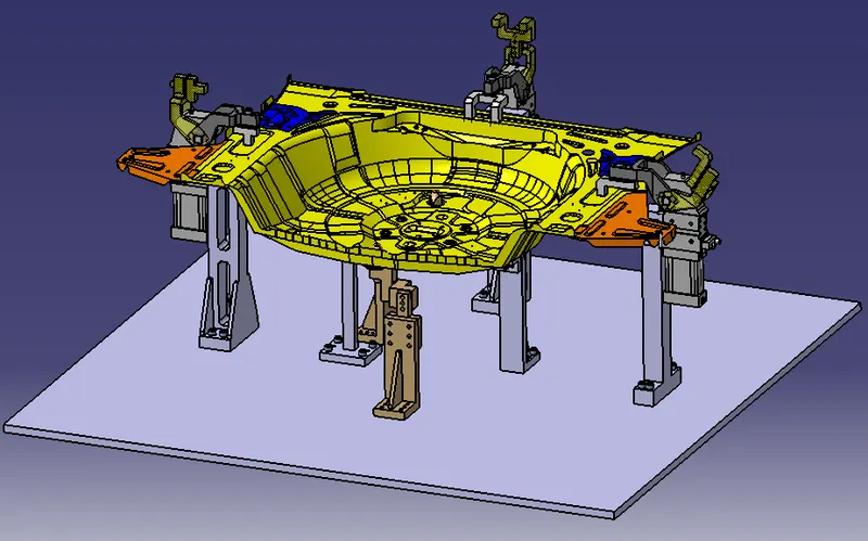
Fig shows: Assembly of clamp units and rest units
- In this project I have designed 3 different types of power clamp units by employing power clamp cylinders and by considering clamping and holding forces for the designs of clamp unit and rest unit for the panel.
- All the fundamentals of clamp unit design are taken into account.
- Purpose of clamp unit
- 3-2-1 principle achieved by clamping
- Clamp plans
- Structured design tree
- How to validate a power clamp cylinder
- How to calculate the clamping force acting at the end of each mylars
- Materials, surface finish & Heat treatment used in the parts of clamp unit.
Software used: CATIA V5
Various units of the design
CLAMP UNIT:
- A clamp unit is a unit designed to clamp/hold the car panel with NC blocks/Mylars/Rest by using a pneumatic clamping cylinder.
- Some of the parts of the clamp unit is clamp arm, finger, rest/backup, L-block, shims, Risers and Pneumatic cylinders.
- Types of clamp units:
- Power clamp unit
- Swivel cylinder clamp unit
- In this project, power clamp cylinders are used for the design.
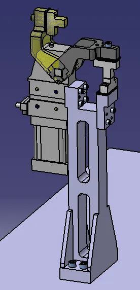
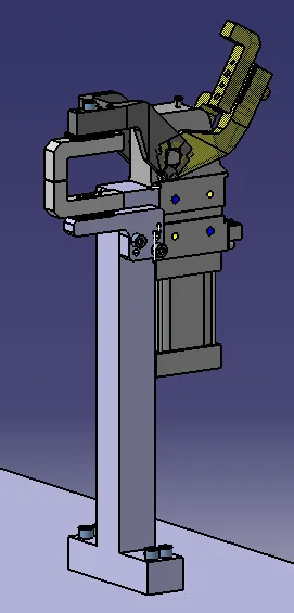
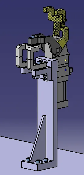
Fig shows: Various types of Clamp units
Fundamentals of clamp unit design:
- It is preferred to design clamp unit with pivot centerline in-line with clamp surface. When possible upto 25mm offset can be acceptable.
- For sigle angular clamping, it is recommended that the centerline of clamp pivot be positioned on plane that is created by surface being clamped, upto 15 degree off normal pivot location can be used in extreme cases where recommended clamping condition cannot be satisfied.
Parts included in clamp unit:
1. Finger /clamp mylar -
- It is a NC block mounted on the clamp arm of the cylinder.
- It is used for clamping / holding the car panel.
- It presses the car panel towards the rest.
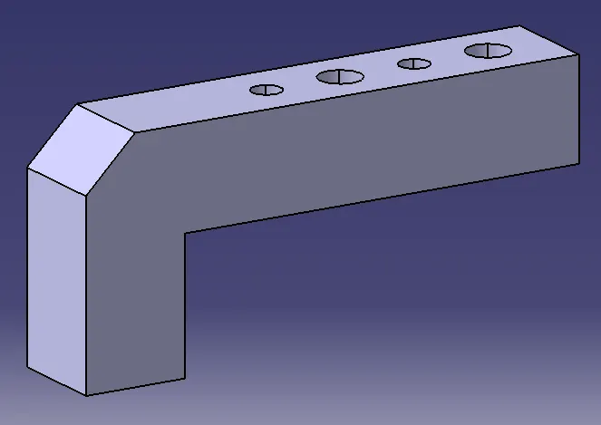
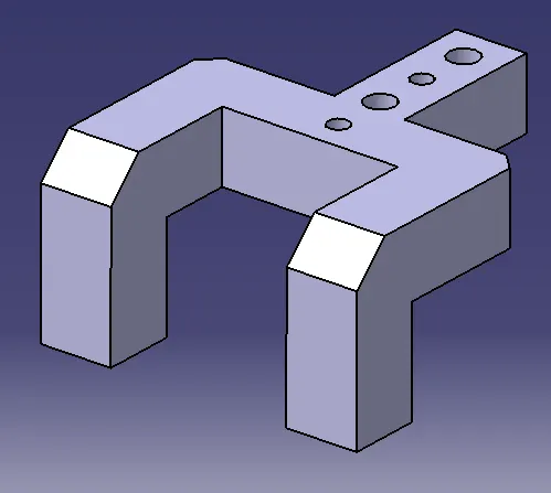
Fig shows: Clamp Mylars
2. Backup / Rest Mylar-
- It is a NC block fixed to the unit to support the car panel.
- It helps in resisting the clamping force of cylinder onto the panel, thus clamping is achieved.
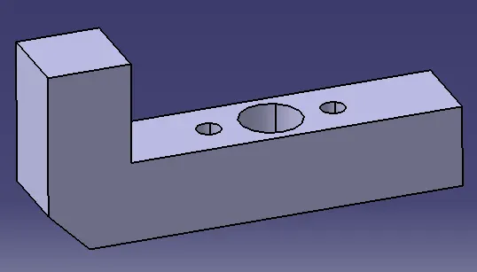
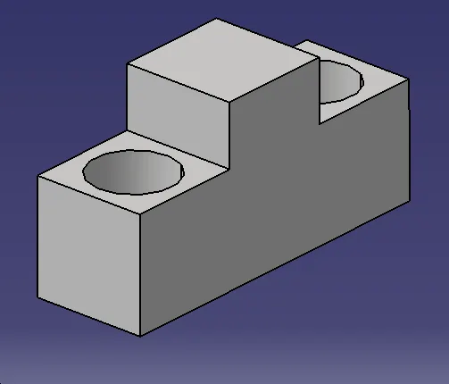
Fig shows: Rest Mylars
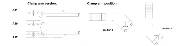
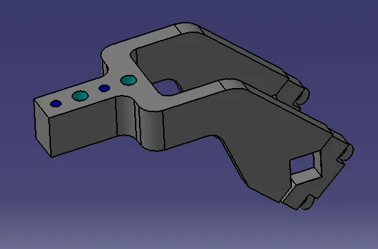
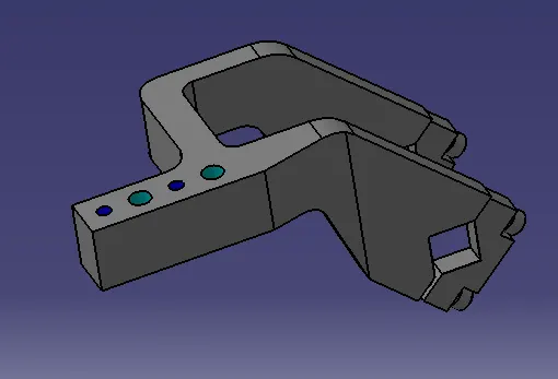
3. Clamp arm-
- Clamp arm is a part of the clamp cylinder and it is a bought out part which is available in some standards.
- All the moveable parts in teh clamp unit are fixed to the clamp arm.
- Clamp arm is different for different bore size of cylinder, it is available in different hole pitch.
- Clamp arm positions:
4. Clamp cylinder-
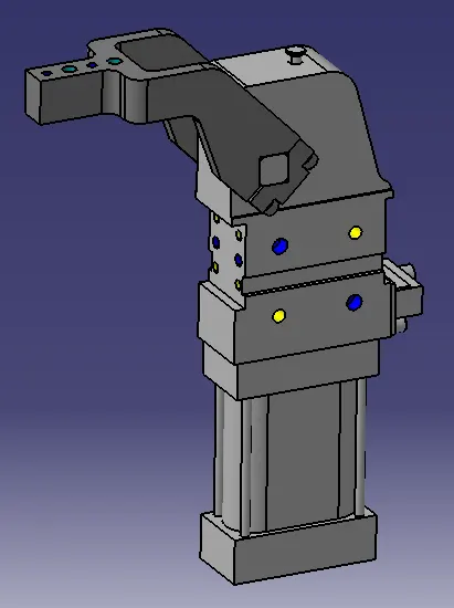
- Clamp cylinder is a pneumatic device which works with the flow of pressurised air.
- Clamp cylinder is a brought out part and some manufacturers are destaco, tuenkers, etc.,
- The clamp cylinder is used to open and close the moving part in the clamp unit.
- It is generally available in 40, 50, 63 and 80 bore capacity.
- Clamp cylinder opens upto 135 degree for horizontal clamp mounting and it opens upto 105 degree for vertical clamping.
REST UNIT:
- A rest unit is used to support the car panel, also it resists the clamping force of the finger with the help of rest mylars & thus clamps the car panel.
- Rest unit consists of rest mylars, shimpacks, riser.
- Holding force should be considered while designing a rest unit.
- Mostly to avoid excess part, to reduce the weight & to reduce the cost of the fixture the rest unit is combined with the clamp unit.
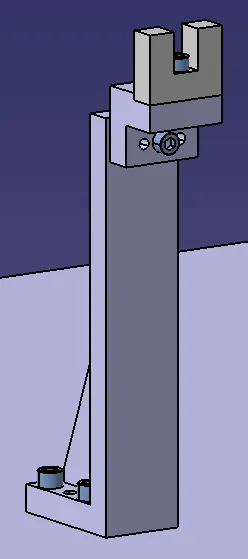
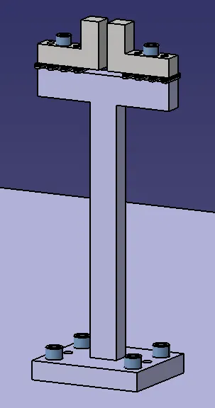
Fig shows: Types of Rest Units
PURPOSE OF CLAMP UNIT AND REST UNIT
- The purpose of clamping tools is to securely hold the workpiece in position without obstructing the production process.
- It prevents the distortion during welding process and other processes.
- High clamping forces combined with compact dimensions are therfore the most important requirements for a clamping tool. For this reason, clamps are also equipped with mechanical transmission gear units.
DESIGN METHODOLOGY:
3-2-1 Principle achieved by clamping and resting:
- The 3-2-1 principle is the fundamental principle of all fixture design. While designing a fixture a major part of time is spent in locating the workpiece in the fixture.
- The best & the most effective method of part location is referred to as the 3-2-1 method. Fixtures work on the 3-2-1 principle.
- 3 locators or supports are placed under the workpiece which establishes the part plane. Three locators are generally positioned at the primary locating surface.
- This restricts 2 axial movements downward & upward and 4 radial movements. As a result the 3 locators arrest six degrees of freedom.
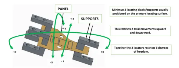
Fig shows: 6 DOF which are restricted by the locators or the clamps
- Thus by using 3-2-1 principle, introducing a minimum of 3 clamping & resting blocks will restrict 6 DOF( 2 axial translational about z-axis & 4 rotational about the x&y axes respectively).
- Remaining 6 DOF are restricted by introducing Pin unit of minimum 2 nos.
- Clamping- The process of holding the workpiece in the jig/ fixture is called clamping. The primary devices used for holding the workpieces are clamps/clamp unit.
- Resting - The car panel will rest on the rest unit. It resists the clamping force of the finger exerted by the clamp cylinder and thus clamps the car panel.
Forces acting in the clamp and rest unit:
while designing a clamp unit 2 forces are considered that act in clamp unit,
- Clamping force
- Holding force
1.Clamping force:
- It signifies the force applied to the workpiece by the drive mechanism via the clamp arm during gripping or clamping operations.
2. Holding force:
- Holding force, on the other hand denotes the maximum force after locking the knee-lever (over centre position, that can be applied by the workpiece on the gripper/clamp arm without destroying the mechanism.
- Therefore, particular attention must be paid to the maximum holding force when, for example during the production process (welding, bonding), there is a possibility of distortion of the component or if the clamp arm is used as a fixed stop.
- If the holding force specified in the technical details is exceeded, this will inevitably result in the destruction of the mechanism, the clamp arm or the bearing position.
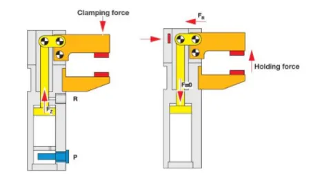
Fig shows: Clamping and holding forces
How to find out the outreach of clamp arm?
By measuring the distance between pivot center of cylinder and the centre of clamping of clamping mylars one can get teh oureach of clamp arm.
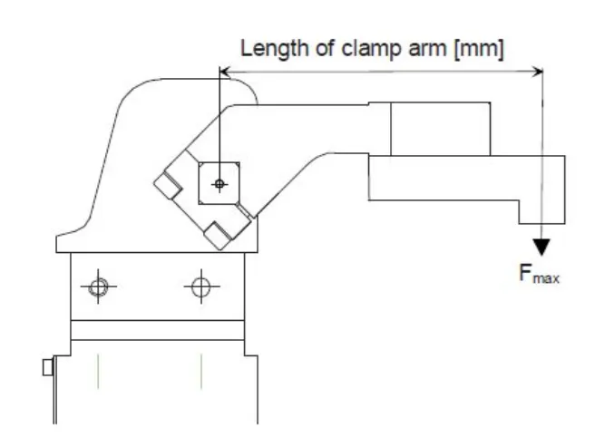
Fig shows: Length of clamp arm
The respective outreach of the clamp arm taken from the clamp unit used in this project are as follows,
- P001_Z03_ST010_03_00_CLAMP_UNIT - outreach of clamp arm is 164mm.
- P001_Z03_ST010_04_00_CLAMP_UNIT - outreach of clamp arm is 120mm.
- P001_Z03_ST010_05_00_CLAMP_UNIT - outreach of clamp arm is 174mm.
By relating the sheet thickness and the outreach as shown above, now the selection of power clamp is done as per our requirements.
The bore capacity of clamp cylinders are found and the power clamp cylinder is selected.
Average Clamping force(Fs) = 1200N (for size of 50 bore dia and mean length of clamp arm)
Design tree:
- It is the process of naming all the assemblies and parts in the specific standards. Different customers have different set of standards to structure a design tree.
- It is an important process which helps us to identify a specific part or assembly as to which project or assembly it belongs to.
- This helps us to avoid the errors during design study, manufacturing, assembly,inspection, etc.,
- If the parts or assemblies are not properly or the design tree is not structured properly, it will create confusion in understanding the design and assembly which may lead to errors.
- Naming of a fixture or a unit or a part gives their place in the specific project or assembly or zone.
- It helps us to identify the quantity of items of same type or different types that are being used in the assembly.
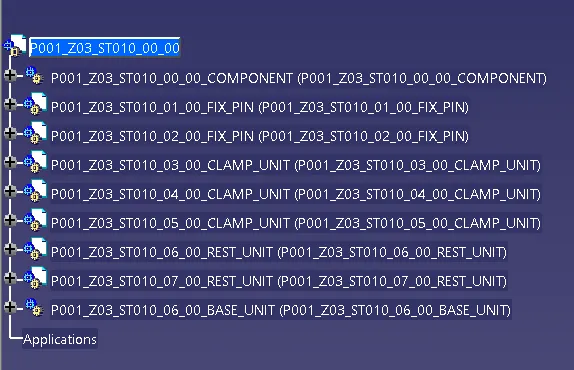
Fig shows: Design tree of this project of clamp and rest unit design
PLP Location and clamp plan:
PLP (Principle Locating Points):
- Principle locating points are the points that are used for the accurate location of the panels sub-assemblies to maintain the geometry of the assembly.
- There are lots of holes on the panel which are not accurate due to stamping operations. So the PLP are defined in the drawings.
- The PLP holes must be very much precise.
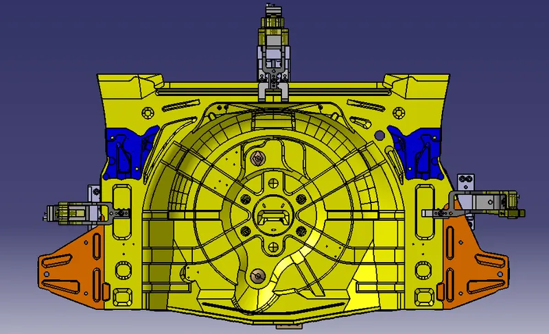
Clamp plan:
- It provides information of location of pins, clamp units, rest units,damp units.
- It is the important input from the customer end.
- The clamp plan/ position should not be changed without the knowledge of the customer.
- It is allowed to change the design little bit here and there but the input design data about the clamp position or pin location must not be changed.
- In clamp plan there is clamp unit,pin unit and it is more detailed. It also gives the Y and Z coordinates from where the designing process of fixture can be started.
Material used:
In general, the materials used for Mylars, Clamp arm, shims, block, blades & risers are:
- Mylars: UHMW, Nylon66, PP, Teflon (polytetrafluroethylene (PTFE). Materials of clamp block and rest block to be decided as per the A class panel or B class.
- Clamp arm: SAE 4140 or SAE 1045.
- Shims / Spacer: S.A.E. 1010 CRS FULL HARD, COLD ROLLED STRIP STEEL S.A.E. 1010 FULL HARD, S.A.E. 1020 HRS, etc.,
- Block: STEEL ASTM A-36, NM STAINLESS, STEEL ASTM A-36, SS type 303 or 304,etc.,
- Blade: STEEL ASTM A-36,etc.,
- Riser: STEEL ASTM A-36,etc.,
HARDNESS:
In general, the hardness of the materials for pins, pin retainers, shims, shim block, blades and risers are 55-60 HRC to a depth of 0.5-0.7 mm after grinding.
SURFACE FINISH:
In general, the surface finishes of the materials for pin, pin retainer, shims, shim block, blades and risers are:
- Clamp arm: Munsell No.3.75YR6/14 safety orange.
- Shims/spacers: BLACK OXIDE FINISH (SURFACES TO BE FLAT AND PARALLEL TO WITHIN 0.012 mm T.I.R.)
- Riser: SURFACES TO BE FLAT, PARALLEL & PERPENDICULAR TO WITHIN 0.015 T.I.R.
CLAMP CYLINDER:
V_50_1_BR3_A40_T12_TUENKERS
- Vario clamp with toggle joint mechanism and continuously adjustable opening angle, Over-centre-lock, Enclosed aluminium housing, Oval-shaped cylinder in the sizes 50, 63, 80.
- Forked clamping arm with standard hole pattern for adapting contour blocks, Continuously adjustable opening angle 5°-135°.
- optional: Weld immune inductive sensing of closed and opened position (T12)
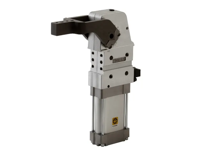
Fig shows: V_50_1_BR3_A40_T12_TUENKERS
- In this project 2 different clamp arms are used with the same clamp cylinder as shown in the above fig.
SPANNARM_KPL_50_A40_242838_TUENKERS ( middle arm) SPANNARM_KPL_50_A41_245811_TUENKERS ( left arm)
IMAGES OF THE DESIGN:
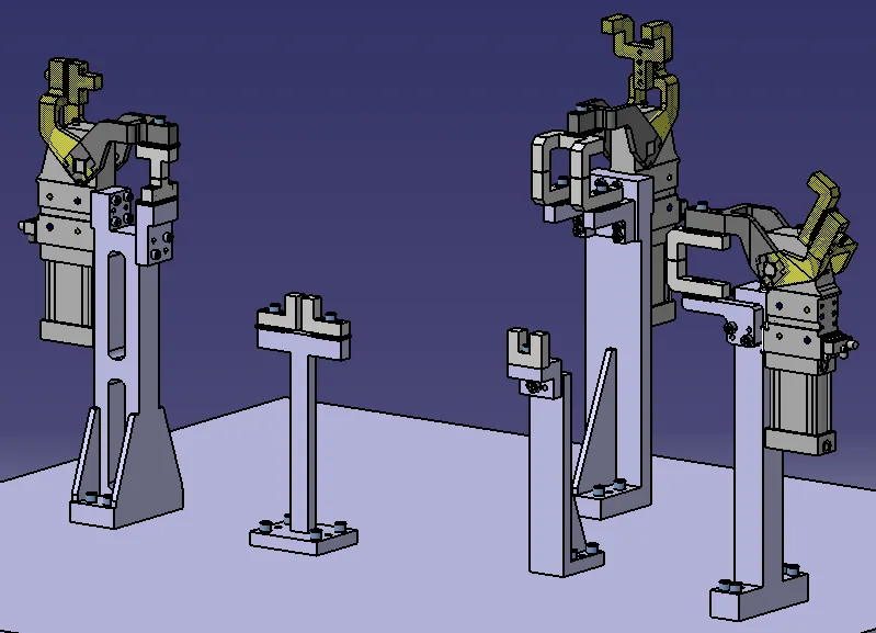
Fig shows: Positions of the clamp units and rest units onto the base unit
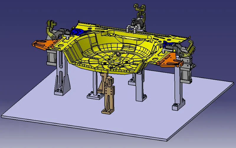
Fig shows: Assembly of the clamp units,rest units,pin units with the panel(a)
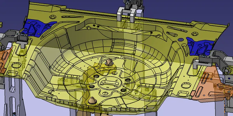
Fig shows: Assembly of the clamp units,rest units,pin units with the panel(b)
CONCLUSION:
Hence as per the objective, design of 2 different types of rest units and design of 3 different types of Power Clamp Unit with different Riser, Blade and Clamp Arm for the given Car Panel is done by empowering power clamp cylinders for the power clamp unit, considering the clamping and holding forces. The 3-2-1 principle is achieved by designing 3 power clamp units and 2 rest units.