Week 4:- Pin Unit Design Challenge
PROJECT : PIN UNIT DESIGN(FIXED PIN & RETRACTABLE PIN)
OBJECTIVE:
To design the pin units for the given component(panel of a car) in both fixed and retractable types and to understand the designing procedures, fundamentals and standards for a pin unit of the BIW fixture design using CATIA V5.
INTRODUCTION:
- Pin unit is a unit designed to locate car panels using pins.
- It consists of riser, blade, block, pin retainer, pin, shims or spacers and cylinders(incase of retractable pin unit).
- Pin unit is a part of the 3-2-1 locating principle of fixture design.
- It restricts 6 degrees of freedom of the part.
Fundamentals of pin unit design:
It is necessary to have 2 pins to locate a car panel where one pin must arrest 4 way(translational) movement and the another one must arrest 2 way(rotational) movement of a car panel.
The axis of the car panel hole and the axis of the pin should be same in general.
The pin tolerance for a geo pin will be of closer tolerence of -0.15mm & for the re-spot pin is -0.28mm.
- Pin should engage at 3 to 5 mm from car panel entry surface.
- All pins should be accommodated with 2-way adjustable shims irrespective of direction of arresting.
- Round pins should be used incase of 4way arresting of car part if the hole is round.
- Round pins can be used for 2 way arresting of car parts only if the hole is slotted.
- Diamond pins should be used for 2 way arrresting of car part if the hole is round.
- Diamond pins should be used incase of 4 way arresting of car parts if the hole is slotted.
Various parts of the pin unit:
Pin:
- Pin is the part which locates the car panel. It can be a make part or standard part.
- It should be grinding surface on shaft with fits onto which the the pin retainer will be fitted.
- The mounting surface of the pin should be fine machined surface.
- The pin should have a step machined surface to lock the rotation, which matches with the pin retainer.
- All machined planes should be perpendicular to the axis of the pin shaft.
- pin must have a provision like tapped hole from the bottom or a v-groove from the side.
- A pin must be hardened (Heat treatment) & black oxide finished in general.
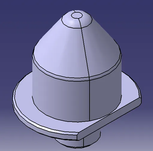
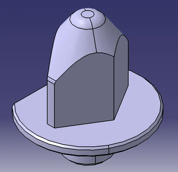
Fig shows : Round pin Diamond pin
Pin retainer:
- The pin retainer is a part which holds the pin in position, it can either be a make part or standard part.
- Pin retainer should have a hole with a fit, onto which the pin will be fixed.
- The pin mounting surface of the pin retainer should be a machined surface.
- The pin mounting surface of the pin retainer should have a step to lock the rotation of the pin.
- The surface of the pin retainer to the blocks should be a machined surface.
- The pin retainer will be fixed to a block or a L-block to the riser with 2 dowel holes(pins) & atleast with 1 screw hole to maintain the tolerance.
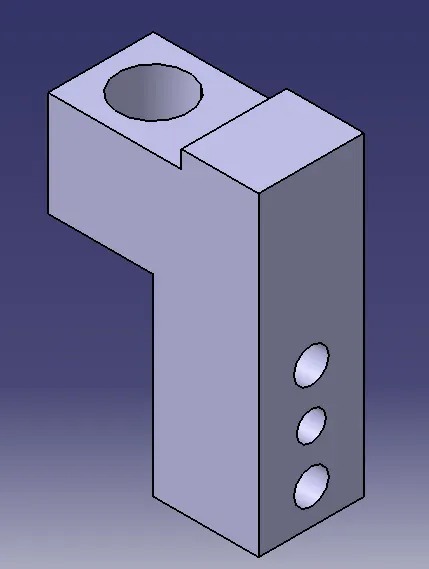
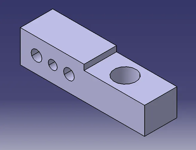
Fig shows: Pin retainers of 2 types
Block:
- Block is used to provide a 2 directional adjustment of pins with the help of shims.
- L-Blocks are most commonly used in general.
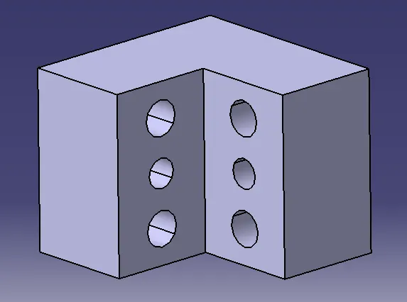
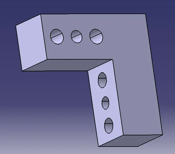
Fig shows : L-Blocks
Shims/Spacers:
- Shims/Spacers are standard parts which are used for adjustments of locators (NC Blocks & Pin retainers) to get precise location of a pin with respect to car part.
- It helps to compensate for deviation in manufacturing processes.
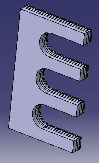
Fig shows: Shimspack
Blade:
- Blade is a plate, which is used to mount assembly of pin, pin retainer & block on a riser.
- The blade can be either a designed part or a standard part.
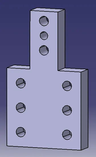
Fig shows: Blade
Riser:
- It is a part on which all the parts are mounted and it is mounted on the base plate of the fixture.
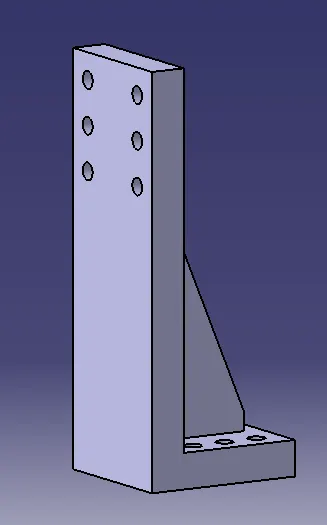
Fig shows: Riser
Dowel holes & machined surface:
- All make parts which are to be assembled should be designed with 2 dowel holes & atleast 1 to 6 threaded/free hole (depends on size). It is to be fine machined for the mounting surface with 3 to 5mm step machining.
1. Design of 2 different types of Fixed Pin Units with Round and Diamond pins:
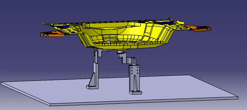
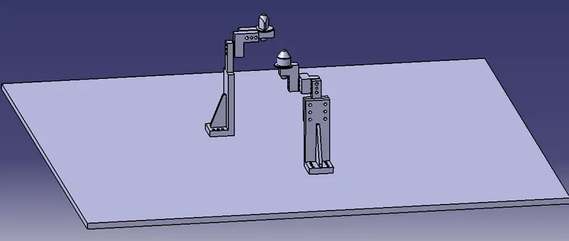
Fig shows: Assembly of Fixed pin unit
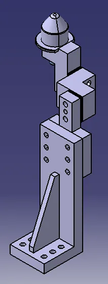
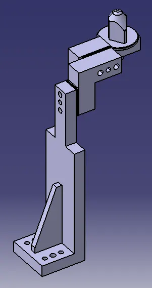
Fig shows: Round pin unit Diamond pin unit
2. Design of 2 different types of Retractable Pin Units with single and double rod mechanism:
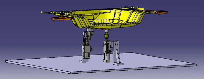
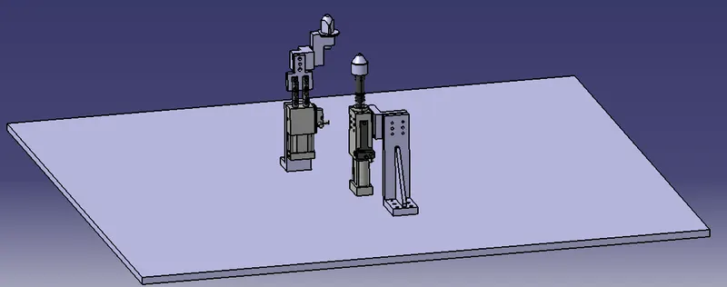
Fig shows: Closed position of the retractable pin units
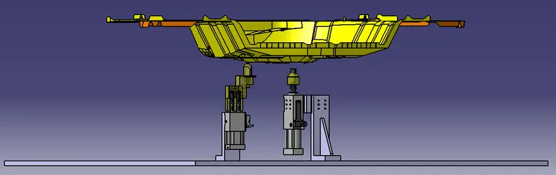
Fig shows: Open Position of the retractable pin units
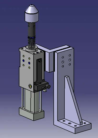
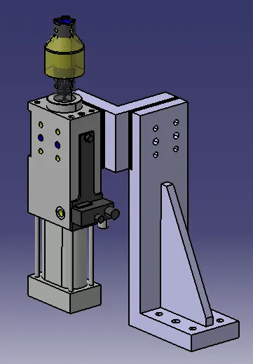
Fig shows: Single rod retractable pin unit(Closed) Single Rod Retractable pin unit(Opened)
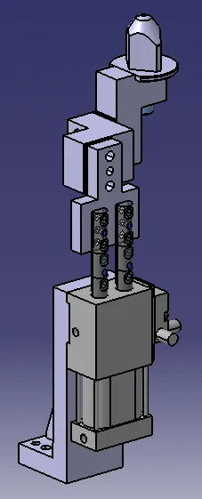
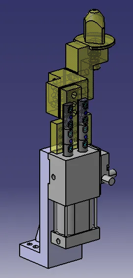
Fig shows: Double rod retractable pin unit(Closed) Double rod retractable pin unit(Opened)