Week 1:- Introduction to BiW and Fixtures Challenge
1. What is BIW and define its parts?
Answer:
BIW
- Body in white (BIW) is the stage in automobile manufacturing in which a car body's frame has been joined together, that is before painting and before the motor, chassis sub-assemblies, or trim (glass, door locks/handles, seats, upholstery, electronics, etc.) have been integrated into the structure. Assembly involves different techniques such as welding, riveting, clinching, bonding and laser brazing.
- Since it acts as a shell of a car within which various parts are assembled, the BIW components must be firm and should have the recquired tensile strength and hardness.
- BIW is the common nomenclature that has been used in the automotive sectors at all departments. A related term is Body in Black which refers to the car body that is manufactured using some composite materials rather than conventional metal. The composite such as carbon fibre are black in colour instead of white.
- It has various frames and panels that are joined together to give a robust structure to the vehicle along with splendid look.
- It has two main types:
- Monocoque body structure
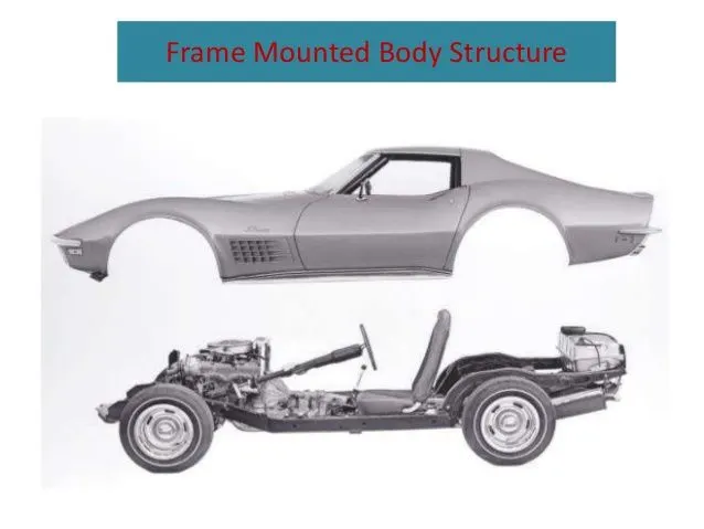
- Frame mounted body structure
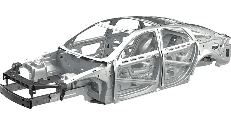
Fig shows: A monocoqe BIW design
BIW PARTS
It consists of various parts that are assembled or joined together to form a structure.
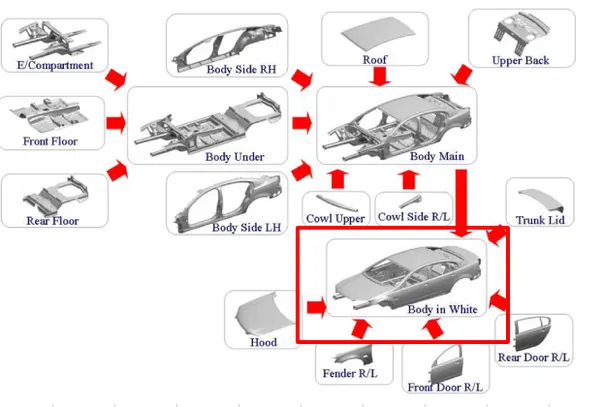
The BIW parts are categorized as:
BODY SIDE
It covers both sides of the car which has some pillar like structures,frames and panels.It includes,
- Body side inner
- Body side outer
Structures of body side
- A- pillar - front most support to the roof
- B- pillar - second support to the roof
- C/D- pillar - C is rear most support to roof in case of two row seating system, it will be 3rd one; D is the 4th most support usually rear side of quarter panel
- Ring panel - a structure panel connecting the rear and front portion
- Quarter panel - rear most panel of a body side structure
- Drip rails/ Gutters - an exposed channel applied to the roof over the side windows to direct water away from the windows.
UNDER FRAME
It acts as the main frame for all other parts since most of the components of the car are welded with this frame. In general it is made rigid so that it can withstand the load and forces exerted from the heavy parts. It includes,
- Front end under frame (ENGINE compartment)
- Rear end under frame (REAR compartment)
- Main floor (FLOOR frame)
In front compartment under frame engine is assembled and in the main frame pillars like A, B & C are welded and trim parts are assembled in main frame.
Panels of under frame:
- Dash panel- provides partition b/w engine and driver cabin
- FRT floor - provides base for seats
- Raiser - connects front floor to rear floor by providing level difference.
- Rear floor - floor on the rear of the car
- Rear wheel house
CLOSURES
As the name suggests they are panels that covers the frame and other structures to provide motion. They come with motions such as open and close. Closures include,
- Doors ( Front and Rear doors)
- Hood ( a hinged panel providing access to the engine compartment)
- Trunk lid ( rear compartment)
Closures form the final stage in BIW assembly before which sides,under frame and roof are joined.
ROOF
It is the upper part of BIW that protects the passengers from bad weather conditions like dusty wind,sunlight,rain,etc., and accidental damages. It is curved and flat like structure in common and has rigid strength. As the component is exposed to such rigorous conditions, careful material selection is really Important. It includes,
- Roof inner
- Roof outer
Other parts like Headers - structural member above the windshield at juncture with the forward edge of the roof panel.
FENDERS
Fenders are small panels that comes over the wheel and connects with side pillars and front engine compartment. They are like the edges of the body with smooth surface finish.
2. What do you understand by BIW nomenclature?
Answer:
BIW NOMENCLATURE
- BIW nomenclature is the naming of various parts of the BIW components as per the language of the nation or the people convenience.
- It has a number of different parts that have different names
- For example: One of the BIW parts is called as cantrail in UK and it is called side roof rail in the USA.
- A brief list of the BIW nomenclatures as per the UK and US description is given below:
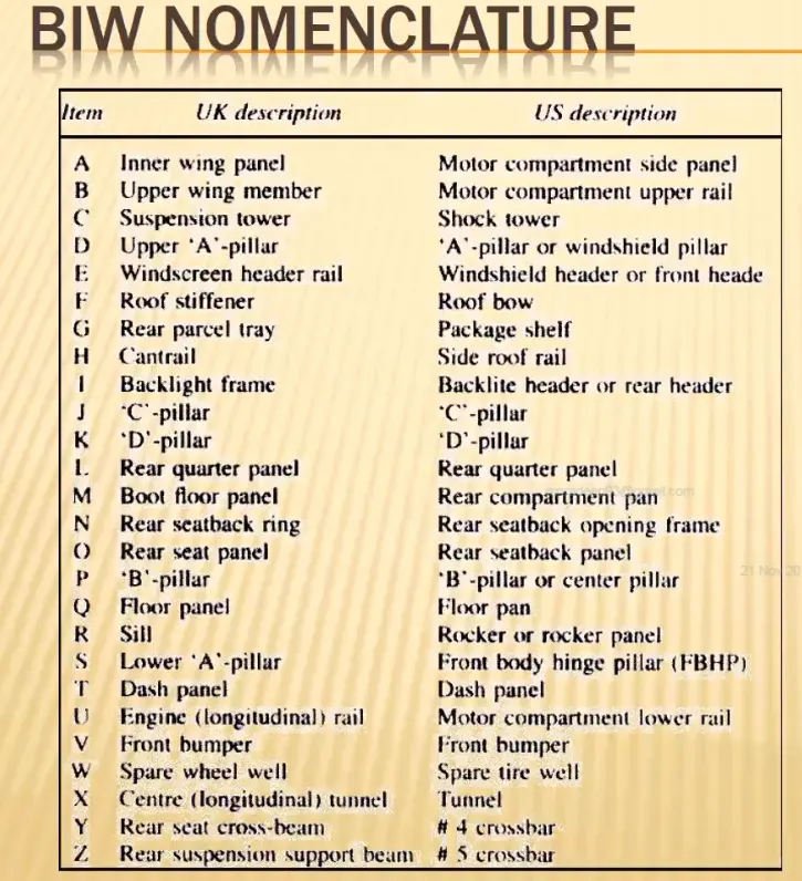
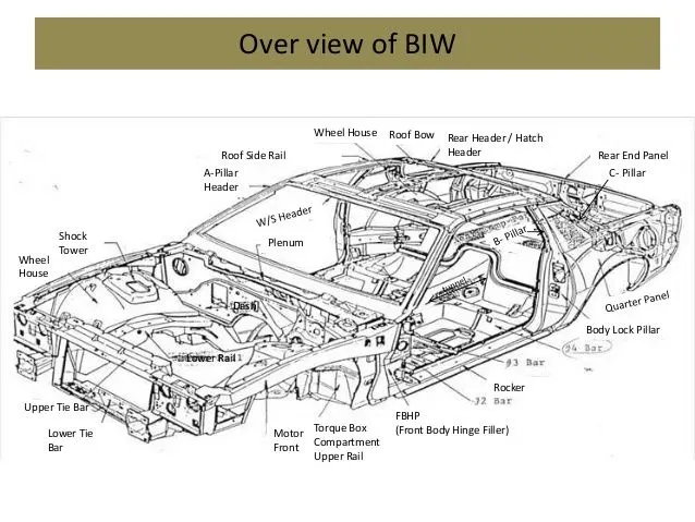
Fig shows: an overview of BIW nomenclature
3. What is fixture and its types?
Answer:
- Fixture is the device which holds the workpiece to be processed (welded) by using 3-2-1 principle.
- A fixture is a work-holding or support device used in the manufacturing industry. Fixtures are used to securely locate (position in a specific location or orientation) and support the work, ensuring that all parts produced using the fixture will maintain conformity and interchangeability.
- Using a fixture improves the economy of production by allowing smooth operation and quick transition from part to part, reducing the requirement for skilled labor by simplifying how workpieces are mounted, and increasing conformity across a production run.
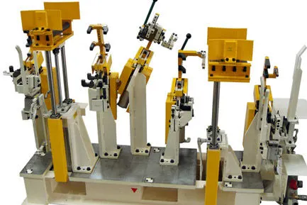
Fig: Shows a BIW fixture
Purpose of Fixtures
- A fixture's primary purpose is to create a secure mounting point for a workpiece, allowing for support during operation and increased accuracy, precision, reliability, and interchangeability in the finished parts. It also serves to reduce working time by allowing quick set-up, and by smoothing the transition from part to part.
- In BIW fixture, the fixtures are designed to hold a number of parts for welding. Hence it is necessary to provide a firm postion for the BIW parts in order to prevent the distortions.
- The parts have to be held in proper location which conforms that the welding process is taken with recquired dimensions.
BIW fixture recquirements
- It should prevent distortions in workpiece during welding process.
- The clamping need to be light but firm which means it should provide the necessary force against the part without damaging the workpiece.
- The part which contacts the workpiece must be a soft material to avoid impression on the workpiece.
- The clamp must be located away from the welding area to avoid collision between the fixture and the welding gun.
Types of Fixtures
- Production fixtures:
- They are used for the mass production purpose. To avoid geometry changes the materials are selected with recquired hardness and the fixture must be firm at its position.
- It should facilitate ease of maintenance,hence the time recquired to assemble and dissemble must be kept as low as possible.
- After processing a no of operations, the fixture must be under maintenance to ensure the geometry and dimension of the upcoming operations.
2. Preproduction operation fixtures(PPO):
- These are the base fixtures that act as the standard one to check the errors and make any changes.
- To check the feasibility of the initial batch production this prototype fixtures are designed and analysed.
- It has the longest cycle time when compared with other type of fixtures since more number of engineers, quality inspector and other workforces are involved. It makes it costs more.
- Due to the high cost and time recquired, we directly go to the production fixtures with the help of some standards and check lists to maintain error free process. This obviously controls the cost of car as much as low.
3. Checking fixtures:
- Checking fixtures are those which donot carry out any operations like welding,gluing,etc., yet they are used to check the dimension and geometry of the product.
- Some gauges are used in this to get the dimension and tolerances of the part. These data are then compared with the designed dimension to approve the product as in correct dimension.
- The tolerance of the geo pin is generally 0.15.
4. What is the basic principle of fixture design?
Answer:
3-2-1 principle:
- The 3-2-1 principle is the fundamental principle of all fixture design. While designing a fixture a major part of time is spent in locating the workpiece in the fixture.
- Generally, a free body has 12 DOF(degrees of freedom):
- 6 Translational DOF
- 6 Rotational DOF
Translational DOF includes:
+X, -X, +Y, -Y, +Z,-Z
Rotational DOF includes:
- Clockwise around X axis (XCW/CROT-X)
- Counter or anticlockwise around X axis (XCCW/ACROT-X)
- Clockwise around Y axis (YCW/ CROT-Y)
- Counter clockwise /anti clockwise around Y axis (YCCW/ACROT- Y)
- Clockwise around Z axis (ZCW/CROT-Z)
- Counter clockwise around Z axis (ZCCW/ACROT-Z)
For proper fixing of parts one should restrict all 12 DOF of the workpiece.
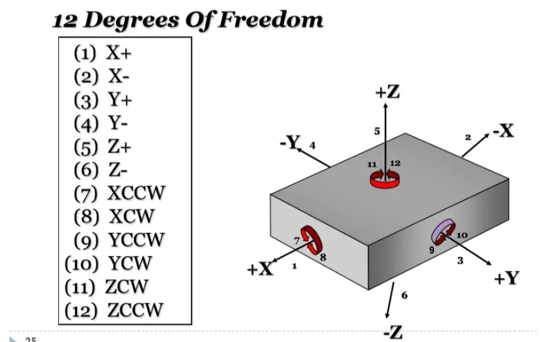
Fig shows: 12 degrees of freedom of a free body
5. Elaborate types of BIW stations.
Answer:
BIW stations
- It is one of the stages in assembly line. The assembly line is divided into zones and each zone has its respective stations.
- The stations are further classified as:
1. Tools
2. Grippers
3. Stands
4. Miscellaneous
Tool station:
A. Geo tool:
- Geo tool accurately defines the geometry of the panel. Usually Tack welding is undergone in the geo fixture.
- It is precise which has a closer pin tolerance of 0.15 in general i.e. If the hole diameter is 15mm, then the pin dia should be 14.85mm.
- The pin must be smaller in size than the hole.
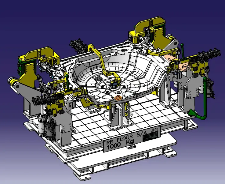
B. Re-spot tool:
- It is a fixture in which the remaining wel spots which are not achieved by the Geo tool are welded for the pre-welded panel.
- This tool provide stiffness to the panel and provides strength since geo tool already ensures the geometry.
- It is because not all the welding operation can be done in single tool since it consumes more time and makes the apparent tool idle.
- It also ensures the geometry of the panel unchanged while it is being taken to the next tool.
- It has a tight positional accuracy i.e. pin tolerance will be -0.28mm.
- For example: If the panel hole size is 20mm, then the pin should be 19.72mm.
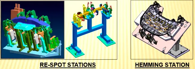
Fig shows: Re-spot station and Hemming station(comes under marriage tool)
C. Marriage tool:
- This tool helps in joining the inner and outer panel assembly.
- In case of closure panel,
- hemming is done.
- All the different parts from various zones are assembled and joined together by using this marriage tool through welding,hemming,gluing,rivetting,etc.,
D. Framer tool:
- This station is followed by the marriage station.
- In this station the roof of the car is attached to the output of the marriage tool.
- Since it forms a frame like structure it is named as framer tool.
E. Checking tool:
- As the name suggests, this tool is used for the checking purpose of the parts or assembly.
- It ensures the coordinates, dimensions, tolerances and position of the automobile parts and assemblies.
- It can be a gauge type,fixed type or automated type.
Grippers
- Grippers are devices that are fixed at the manipulator of the robot or the end effector for holding the car panel, lifting it and droping it at the desired destination.
- It is one of the parts of an automated system and can be attached to the robot or it can be a part of fixed automated system.
Fig shows: Automated robot with grippers
A. Material handling gripper
- These type of grippers are used in handling materials such as picking up a panel and droping it at another station.
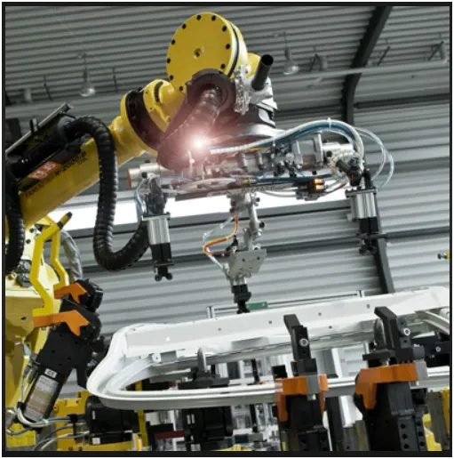
Fig shows: Material Handling Gripper
B. Process grippers
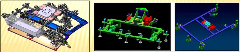
- This type of gripper can carry out some specific process like welding,gluing,riveting,etc., in addition to material handling.
- It can do only one process at a time which means it cannot do multi-tasking at a time.
- Both welding and material handling cannot be done simultaneously.
C. Combo grippers
- This type of gripper can do multi-tasking at the same time i.e. both welding and material handling processes are done simultaneously.
- They are used for handling car panels and at one side of the gripper the welding gun/glue gun is fixed.
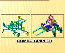
Fig shows: Combo gripper
D. Dual gripper
- This gripper has two grippers at either side of the fixture which is mainly designed for handling panels that have inner and outer panels.
- Dual gripper = Gripper1 + Gripper2
- These are material handling grippers.
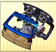
Fig shows: Dual gripper
Stands
- Stands are used to hold the components like panel,welding gun,gluing gun,et., Which are permanently fixed to the ground at the specific stations.
- The stands are classified as:
- Pedestal stand
- Gluing/sealer stand
- Docking stand
- Date stamp stand
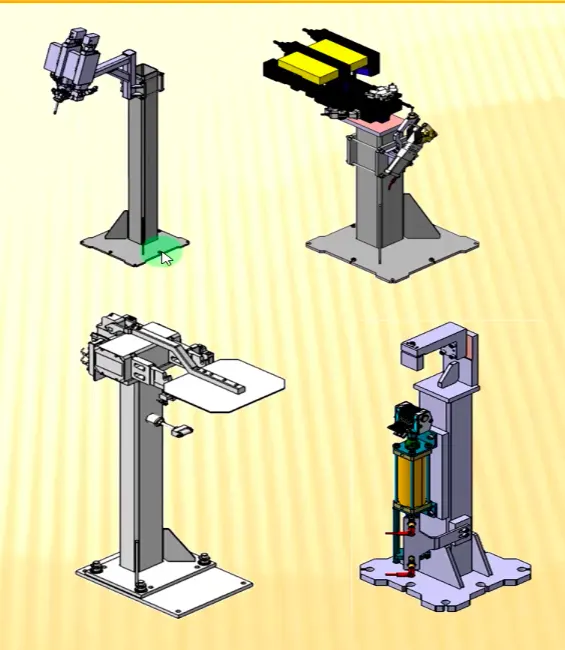
Fig shows: All the above mentioned stands
1. Pedestal stand
- In this type, the weld gun is fixed to the stand permanently grounded to the floor.
- The gripper carrying the panel approaches the weld gun and welding is done by the fixed weld gun.
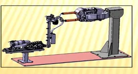
Fig shows: pedestal stand
2. Gluing/sealer stand
- Gluing or sealer stand is fixed to the welded or standard stand that is permanently grounded to the floor.
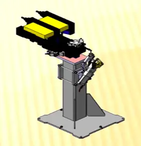
3. Docking stand
- This stand is mainly designed for robots that undergo multitasking like material handling and welding yet they cannot carry both due to some limitations( pay load capacity of the robot or space constraint).
- The robot drop and pick the carried panel/ welding gun after completing the respective operations with the help of docking stand.
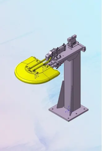
Fig shows: Docking stand
4. Date stamp stand
- Every manufactured product has some data to be printed or embossed on it like serial no,date,batch no,etc.,
- The process of embossing the date on the panel is done using the date stamping device mounted to this stand.
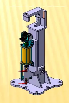
Fig shows: Date stamping stand
Miscellaneous stand
- Curing
- After gluing it takes some time to cool or dry.
- So the glued panels are held/hung by the curing and moved to the next station. In the meantime, it is cooled.
2. Buffer stand
- Buffer stand acts as a storage stand which has similar parts that can carry n number of panels.
- During the time of maintenance, the panels ought to be kept and stored for supplying. At this time the buffer stands are very much helpfull and it can be moved to other places for inventory purposes.
3. Takeout trolleys
- They are used to take out the panels outside for inspection purposes by using trolleys.
- Inspection is carried out to determine whether the process is going in a right or wrong direction in between the cycle.
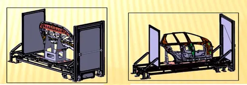
Fig shows: Takeout trolley
4. Conveyor
- The conveyor is the rotating path that carries the panel to the upcoming stations.
- It may be a chain or belt conveyor that has some fixture like structure which holds the panel when moving to other stations.
Fig shows: Conveyor holding BIW
6. What are the basic terminologies used in the BIW fixture?
Answer:
The basic terminologies used in BIW fixture are:
A. NC/Mylars/Fingers:
- Mylars hold the workpiece from top and bottom side of the panel.
- They are also called fingers that holds the workpiece without any distortion during welding process.
- It prevents the distortions caused by welding stresses.
- There are two parts:
- Clamping mylar - the top mylar part
- Resting mylar - the bottom mylar part
B. Principle locating point:
- These are the points that act as a guide for accurate location of the panels,sub-assemblies in the fixture to obtain perfect geometry.
- There are lots of hole which are not accurate due to stamping.
- The hole(PLP) must be very precise and is mentioned in the drawing.
C. Risers:
- They are stand like structures that gives height to the assembly.
- There are different types like L-type,square tube riser,etc.,
D. Blade:
- Blades are the plates which are attached to the riser.
- Other parts like cylinder,arms,etc., are mounted on the blade.
E. Shims:
- Shims are small plates(tapered or wedged) that are used to fill some gaps between objects especially between the Mylars and the panel.
- They come with thickness of 0.1mm,0.2mm,0.5mm,etc.,
- We give tolerance to all fixtures. Due to this tolerance, the Mylars will either lift or goes down from its defined position.
- If the mylar goes down it will leav impression on the panel and bend it.
- If the mylar goes up there will be distortion during welding and it deforms the geometry.
- Types of shims-
- Wood shims
- Stone shims
- Plastic shims
- Metal shims
- Paper shims
F. Rough locators:
- The operator may place the part in wrong orientation unknowingly. Hence the rough locators are used to guide the operator to place it in desired orientation correctly.
- It is a part of fool proofing.
G. Hardwares:
- Hardwares are the fasteners which are used to connect the parts or lock the parts together.
- For example: Hex headbolts, hex nuts, spring washers, allen bolts, etc.,
H. CMM:
- It is the Co-ordinate Measuring Machine which is used for measuring the geometry of physical objects by sensing the discrete points on the surface of the object using probes.
- Various types of probes are used like mechanical,laser,optical,etc.,
- It generates the report by comparing the data observed with the CAD file data.
I. Units:
- The various parts of the fixture are categorized as some units. These units after assembly forms the fixture.
- There are different units like pin unit,base unit, clamping unit,etc.,
J. Number plates:
- To recognize units easily aluminium embossed plates are fitted to the units.
- Each unit has a number which is embossed on the aluminium plate for future references.
K. Coordinate plate:
- In every fixture there will be tooling holes, where every unit will be fitted.
- They reflect the position of the units and the panels.
- They will be helpfull for checking in CMM.
L. Name plate:
- All the basic informations such as panel name,panel number, fixture name, fixture number, fixture weight,fixture type, company name,etc., will be embossed on the name plate.
M. Clamp arm:
- It is a part of the clamping unit that holds the clamp and mylars.
- Clamp arm is rotatable and it holds the panel firmly.
N. Pivot:
- It is the axis about which the clamp arm rotates.
O. Class A Surface/ Skin care:
- The outer panels such as hood,door,roof,deck,back door,fender are visible to the customer and it should be asthetically designed.
- There should not be any scratches or dent in the surface of the panel. Hence, soft materials like nylon are used in the clamping unit to get a firm and smooth grip.
P. Reed switches/ Sensors:
- Reed switches are electric parts that are used in automated fixture which runs through PLC.
- They are operated by an applied magnetic field which detects the position of the cylinder.
- They are fixed at the sides of the cylinder to confirm the clamping of panels.
- Sensors are also electric component that are placed at various location where the main part of panel and subassemblies are placed.
- Incase the operator forgot to place a sub-assembly in the fixture and all the welding operations are undertaken, then the missed part cant be added to the assembly.
- Moreover it costs more money and consumes more time. To avoid this, sensors are placed at various locations to ensure the position of all parts.