Week 8 - Universal Joint
Objective:
A universal joint (universal coupling, U-joint, Cardan joint, Spicer or Hardy Spicer joint, or Hooke's joint) is a joint or coupling connecting rigid rods whose axes are inclined to each other, and is commonly used in shafts that transmit rotary motion.
The main objective here is to perform a Transient structural Analysis on a universal joint mechanism with a spring using three different materials such as Structural Steel, Stainless Steel and Titanium alloy for the base kuckle and the spring. This simulation aims to obtain the Equivalent stress and total deformation for all the three cases and compare them. Basically we will be studying the effect of this motion on the spring since that is the only non-rotating part
Preprocessing for the analysis:
1. Geometry creation
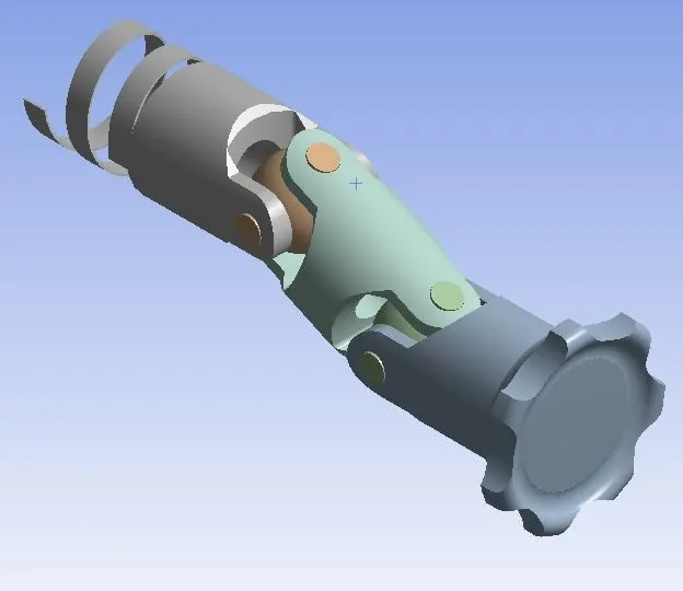
The model required for this challenge was obtained from the one given in the problem. The model is checked in modeler or spaceclaim for any irregularities in the model.
2. Material Selection
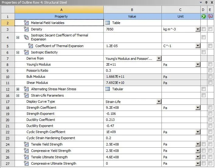
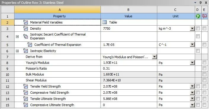
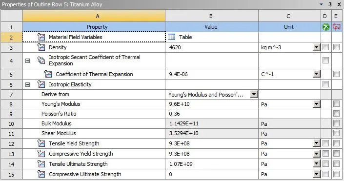
Three materials were assigned to the spring and the driven shaft/base knuckle viz., Structural steel, Stainless steel abd Titanium alloy. These were all selected from the general materials menu in engineering data. The proeprties of materials are attached here,
3. Connections
In this case, no contacts are to be defined for any of the parts. Any predefined contacts were deleted. This has been done to study the results if no contact has been established.
However, 7 joints have been defined to establish the motion of the components.
- Fixed spring Joint- The spring is fixed at one end for all DoF to study the coiling of the spring and stresses generated due to the coiling.
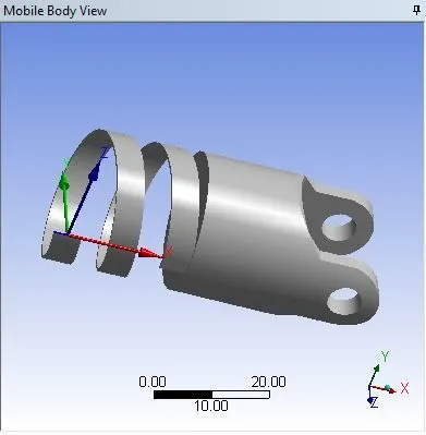
- Base Knuckle revolute joint- The Base knuckle/driven shaft is given a free DoF in z-axis to allow fee rotaion in response to rotation of intermediete knuckle/link.
- Source Knucle revolute joint- The Source knuckle is the link inducing motion in the mechanism. It is allowed to rotate in the z-axis to be given a joint load later on in the analsysis.
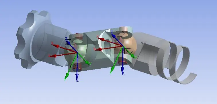
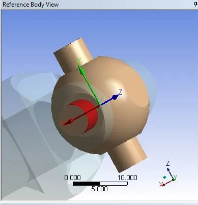
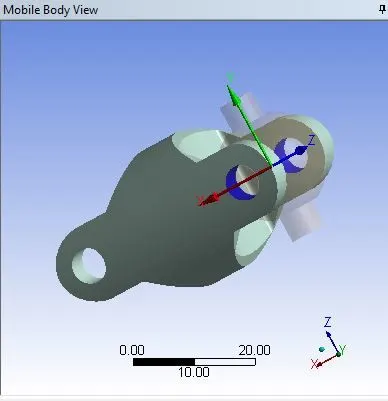
- Knuckle to ball revolute joints- All three knuckles are given rotation DoF relative to the ball joint. There are a total of 8 joints like this, 4 at each ball joint and joints are to be created for each and every joint. In each case, the ball is the referecen body and the knuckle is the mobile body. Care is to be taken that the axes of revolution of each joint matches the actual axis of rotation corresponding to the rotation of the links. In current simulation, two rotation joints for the same knuckle were merged as their axes of rotation were the same.
4. Meshing
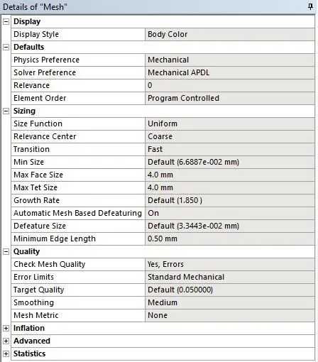
The mesh considered in this simulation was an automatic one, however the size of elements was defined as 4 mm for adequate accuracy of solution.

5. Analysis settings
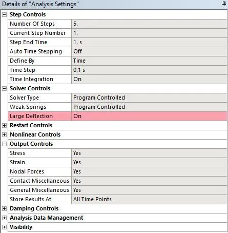
This problem was solved in 5 steps. The first step was given an time step of 0.1 s, with Auto timestepping kept OFF and with weak springs being programme and large deflection turned ON. All outputs were switched to 'yes'.
For steps 2-4, both Auto timestepping was turned OFF while giving a time step of 0.1 s. Rest of the properties were similar to timestep-1 i.e., Weak springs stiffness was programme controlled and large deflections were allowed to be ON. All outputs were switched to 'yes'.
The analysis setup properties are shown below,
6. Loads and Boundary conditions
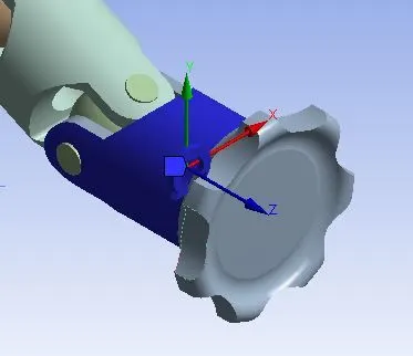
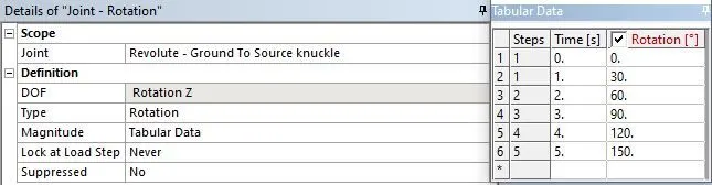
There was only one joint considered in boundary condition, the joint load was given to the Source knuckle-ground revolute joint. Rotation with z-axis was given in 5 steps of 30 deg. each. The joint properties are given below.
Solution and postprocessing:
1. Equivalent stress
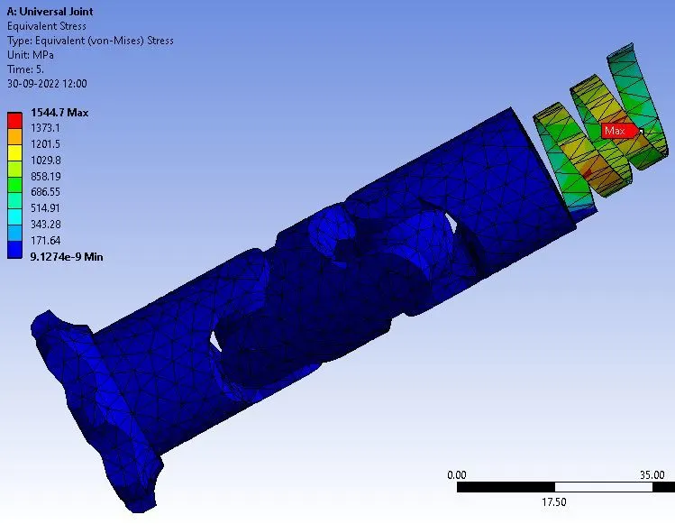
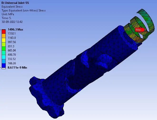
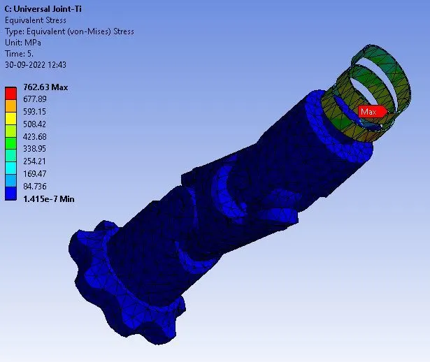
The above results are for spring of structural steel, stainless steel and Ti alloy in that order. It was observed that the max stress was observed in the structural steel model (1544.7 MPa) followed closely by Stainless steel model of the spring (1496.3 MPa) ehile Ti alloy showed leaset amount of stress in the three models (762.3 MPa).
2. Total Deformation
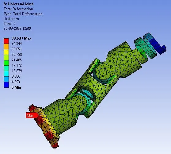
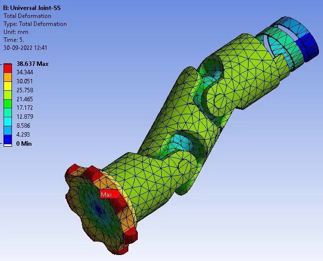
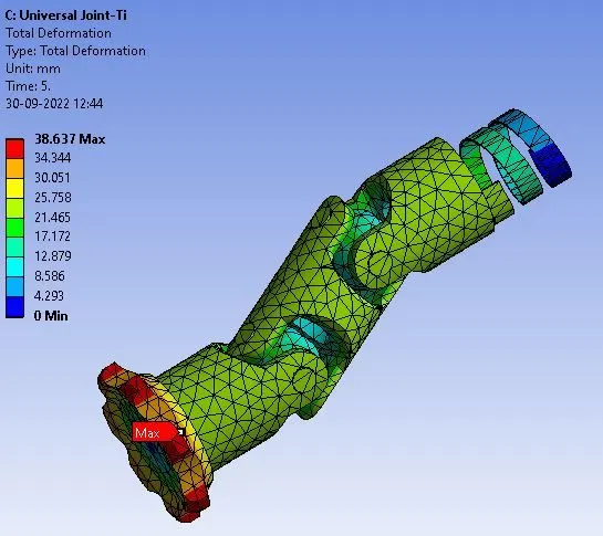
The above results are for spring of structural steel, stainless steel and Ti alloy in that order. It can be observed that total deformation in all three cases match exactly since that input was the same for all three materials. It can also be seen that max deformation occurs at the same spot in all three cases which is expected since that is the pin t of application of force for motion of the mechanism.
Results:
The results requested in the chaleenge were equivalent stresses in the spring and the total deformation in the model. It was expected that a comparison be carried out for the three materials of the base knuckle materials.
| Structural steel | Stainless steel | Ti-alloy | |
| Equivalent Stress (MPa) | 1544.7 | 1496.3 | 762.3 |
| Total Deformation (mm) | 38.637 | 38.637 | 38.637 |
- It has been noted that a decreasing trend in stress values has been observed as we move from structural steel to Stainless steel to Ti-alloy.
- This can be explained by the relative strength of each material
- Ti-alloy has the highest strength of all three materials with a yield strength of 9300 MPa hence shows the least amount of stress.
- Structural steel and stainless steel have much lower strengths and show higher induced stresses.
- Stainless steel is slightly stronger than structural steel with their strengths being 2070 MPa and 250 MPa respectively. Thus proving the trend in increase in stress between structural steel and stainless steel.
- It was also noted that the total deofrmation in all three cases, thereby proving that a change in material does not affect the deformation of the bodies.