Week 8 - Simulation of a backward facing step in OpenFOAM
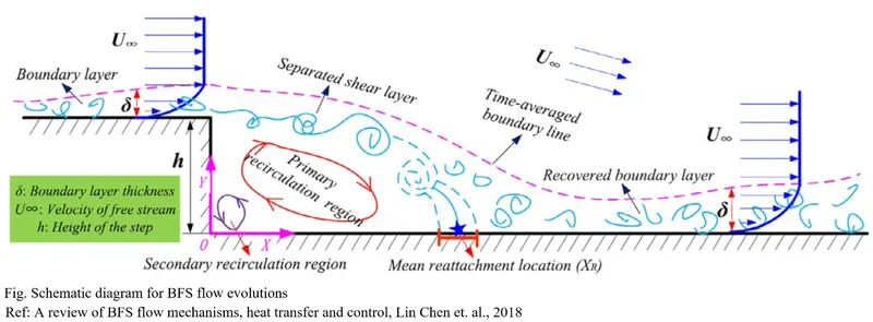
Backward-Facing Step (BFS) flow is one representative separation flow model, which is of significance in both theoretical and engineering development. Various applications for BFS flow can be found in our daily life, such as the airfoils at a large angle of attack, the spoiler flows, separation flow behind a vehicle, inlet tunnel flow engine, or inside a condenser/combustor, and also the flow around a ship or a building. It is a basic model that involves the most important features of a separated flow: free shear layer separation, vortex evolution, and re-attachment.
To simulate the flow, the domain is divided into several grid points. To generate the grid the domain is first divided into blocks. Below the image for the domain and the divided block is shown.
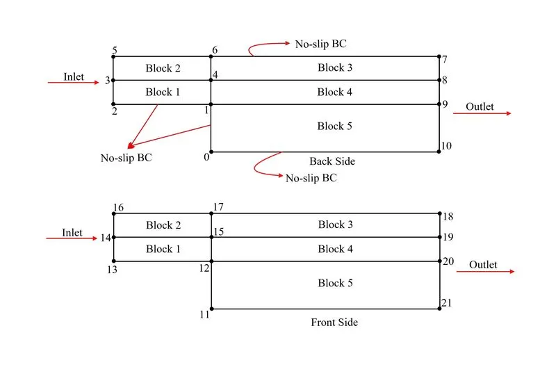
The numbering of the vertices is done randomly. This numbering of vertices helps in defining the blocks in OpenFOAM. Below the code for the blockMeshDict is attached.
/*--------------------------------*- C++ -*----------------------------------*\
  =========                 |
  \\      /  F ield         | OpenFOAM: The Open Source CFD Toolbox
   \\    /   O peration     | Website:  https://openfoam.org
    \\  /    A nd           | Version:  8
     \\/     M anipulation  |
\*---------------------------------------------------------------------------*/
FoamFile
{
    version     2.0;
    format      ascii;
    class       dictionary;
    object      blockMeshDict;
}
// * * * * * * * * * * * * * * * * * * * * * * * * * * * * * * * * * * * * * //

convertToMeters 1;

vertices
(
    (0 0 -0.005)				//0
    (0 0.01 -0.005)				//1
    (-0.08 0.01 -0.005)			//2
    (-0.08 0.015 -0.005)			//3
    (0 0.015 -0.005)				//4
    (-0.08 0.02 -0.005)			//5
    (0 0.02 -0.005)				//6
    (0.12 0.02 -0.005)				//7
    (0.12 0.015 -0.005)			//8
    (0.12 0.01 -0.005)				//9
    (0.12 0 -0.005)				//10

    (0 0 0.005)				//11
    (0 0.01 0.005)				//12
    (-0.08 0.01 0.005)				//13
    (-0.08 0.015 0.005)			//14
    (0 0.015 0.005)				//15
    (-0.08 0.02 0.005)				//16
    (0 0.02 0.005)				//17
    (0.12 0.02 0.005)				//18
    (0.12 0.015 0.005)				//19
    (0.12 0.01 0.005)				//20
    (0.12 0 0.005)				//21
);

blocks
(
    hex (2 1 4 3 13 12 15 14) (80 5 1) simpleGrading (1 1 1)				// Block 1
    hex (3 4 6 5 14 15 17 16) (80 5 1) simpleGrading (1 1 1)				// Block 2
    hex (4 8 7 6 15 19 18 17) (120 5 1) simpleGrading (1 1 1)			// Block 3
    hex (1 9 8 4 12 20 19 15) (120 5 1) simpleGrading (1 1 1)			// Block 4
    hex (0 10 9 1 11 21 20 12) (120 10 1) simpleGrading (1 1 1)			// Block 5
);

edges
(
);


boundary
(

    inlet
    {
        type patch;
        faces
        (
            (3 14 16 5)
            (2 13 14 3)
        );
    }
    outlet
    {
        type patch;
        faces
        (
            (8 19 18 7)
            (9 20 19 8)
            (10 21 20 9)
        );
    }
    bottom
    {
        type wall;
        faces
        (
            (0 11 21 10)
            (2 13 12 1)
            (1 12 11 0)
            (16 5 6 17)
            (17 6 7 18)
        );
    }

    frontAndBack
    {
    	type empty;
    	faces
    	(
    		(2 1 4 3)
    		(3 4 6 5)
    		(4 8 7 6)
    		(1 9 8 4)
    		(0 10 9 1)

    		(13 12 15 14)
    		(14 15 17 16)
    		(15 19 18 17)
    		(12 20 19 15)
    		(11 21 20 12)
    	);
    }

);
mergePatchPairs
(
);

// ************************************************************************* //
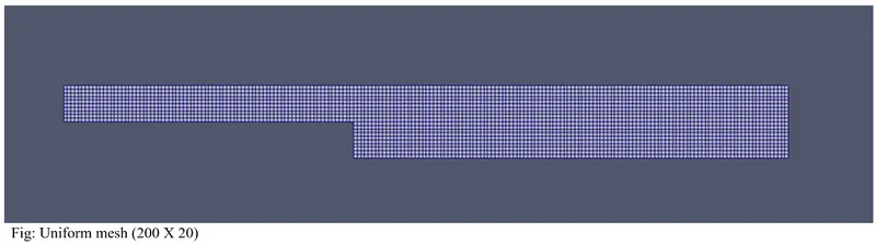
This code is for a grid having uniform spacing. After defining the blocks, the faces are defined as the inlet, outlet, bottom, etc. This naming is user-defined but should be kept consistent with the script file (stored in the 0 folder named as U and p) where the initial and boundary condition is defined.
The mesh generated is as below:
The following boundary condition is used for the simulation:
1. At inlet: U = 1m/s, and pressure gradient = 0.
2. At outlet: Velocity gradient =0 and gauge pressure =0
3. At the top wall, bottom wall, and the step no-slip boundary condition is defined, and pressure gradient is made to zero.
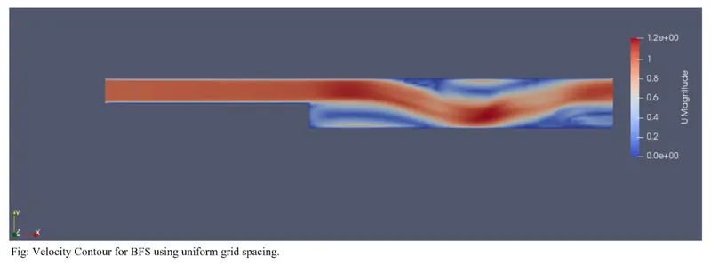
The following result is being obtained:
To simulate the problem following parameter is being used:
`nu=14.88xx10^-7m^2/sec`
`dt = 5xx10^-4sec` and end time = 1 sec.
NOTE: The end time is usually kept around 4-5 times of the time taken by the flow to cross the domain.
In this problem, a uniform velocity of 1m/sec is being given at the inlet and the domain length is 0.2 m.
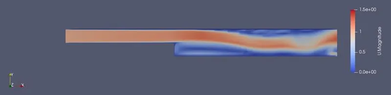
The formation of the circulation region, reattachment of the flow, and then the formation of the boundary layer is observed.
As the variation of pressure and velocity near the wall and at the step is large so to capture those variations the grid should be kept fine at these locations. So, again the grid is being generated by using the grading factor.
The grading factor is defined as the ratio of the size of the end cell to the size of the first cell.
Below the code of the blockMeshDict is attached:
/*--------------------------------*- C++ -*----------------------------------*\
  =========                 |
  \\      /  F ield         | OpenFOAM: The Open Source CFD Toolbox
   \\    /   O peration     | Website:  https://openfoam.org
    \\  /    A nd           | Version:  8
     \\/     M anipulation  |
\*---------------------------------------------------------------------------*/
FoamFile
{
    version     2.0;
    format      ascii;
    class       dictionary;
    object      blockMeshDict;
}
// * * * * * * * * * * * * * * * * * * * * * * * * * * * * * * * * * * * * * //

convertToMeters 1;

vertices
(
    (0 0 -0.005)				//0
    (0 0.01 -0.005)				//1
    (-0.08 0.01 -0.005)			//2
    (-0.08 0.015 -0.005)			//3
    (0 0.015 -0.005)				//4
    (-0.08 0.02 -0.005)			        //5
    (0 0.02 -0.005)				//6
    (0.12 0.02 -0.005)				//7
    (0.12 0.015 -0.005)			        //8
    (0.12 0.01 -0.005)				//9
    (0.12 0 -0.005)				//10

    (0 0 0.005)				        //11
    (0 0.01 0.005)				//12
    (-0.08 0.01 0.005)				//13
    (-0.08 0.015 0.005)			        //14
    (0 0.015 0.005)				//15
    (-0.08 0.02 0.005)				//16
    (0 0.02 0.005)				//17
    (0.12 0.02 0.005)				//18
    (0.12 0.015 0.005)				//19
    (0.12 0.01 0.005)				//20
    (0.12 0 0.005)				//21
);

blocks
(
    hex (2 1 4 3 13 12 15 14) (80 5 1) simpleGrading (0.2 5 1)				// Block 0
    hex (3 4 6 5 14 15 17 16) (80 5 1) simpleGrading (0.2 0.2 1)				// Block 1
    hex (4 8 7 6 15 19 18 17) (120 5 1) simpleGrading (5 0.2 1)			// Block 2
    hex (1 9 8 4 12 20 19 15) (120 5 1) simpleGrading (5 5 1)			// Block 3
    hex (0 10 9 1 11 21 20 12) (120 10 1) simpleGrading (5 0.2 1)			// Block 4
);

edges
(
);


boundary
(

    inlet
    {
        type patch;
        faces
        (
            (3 14 16 5)
            (2 13 14 3)
        );
    }
    outlet
    {
        type patch;
        faces
        (
            (8 19 18 7)
            (9 20 19 8)
            (10 21 20 9)
        );
    }
    bottom
    {
        type wall;
        faces
        (
            (0 11 21 10)
            (2 13 12 1)
            (1 12 11 0)
            (16 5 6 17)
            (17 6 7 18)
        );
    }

    frontAndBack
    {
    	type empty;
    	faces
    	(
    		(2 1 4 3)
    		(3 4 6 5)
    		(4 8 7 6)
    		(1 9 8 4)
    		(0 10 9 1)

    		(13 12 15 14)
    		(14 15 17 16)
    		(15 19 18 17)
    		(12 20 19 15)
    		(11 21 20 12)
    	);
    }

);
mergePatchPairs
(
);

// ************************************************************************* //
The grid generated is as follows:
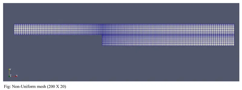
In this case, all the parameters remain the same only the grid is changed for the domain. The result obtained is as follows:
In this challenge, the objective is to generate the mesh by dividing the domain into blocks first. During this process following things should be kept in mind:
1. To define the block, the vertices should be written in a proper format.
2. The surfaces defined in the blockMeshDict is user-defined and should be kept consistent with the script file of U and p, where the initial and boundary condition is defined.
3. While grading of grids is done, it should be kept in mind that it is consistent with the adjacent blocks so that the grid lines of adjacent blocks align with each other.
While running the simulation the time step needs to be changed according to the kinematic viscosity of the fluid or else the CFL number exceeds beyond a limit and the simulation will stop showing an error message.