Week 8 - Simulation of a backward facing step in OpenFOAM
Aim:
To simulate an incompressible-laminar-viscous flow through the backward-facing step geometry.
Given data:
The geometry dimensions and domain specifications
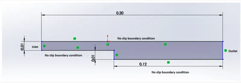
Mesh specification
- Number of cells along the x-direction = 200
- Number of cells along the y-direction = 20
Two cases will be simulated one with a grading factor of 1 and the other with a grading factor of 0.2 to provide mesh refinement close to the walls.
Water at 20C is chosen as the fluid for simulation whose property of concern being kinematic viscosity at 20C can be defined as `1*10^-7 m^2/s`
Method followed:
Mesh generation:
The mesh was generated using the `blockMesh` inbuilt technique available in OpenFOAM. This technique was used to divide the domain into 5 major blocks and then define the grid parameters for these blocks. The following image represents the technique followed:

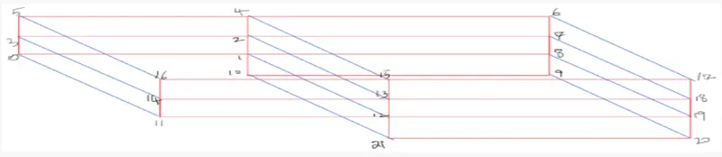
Using this method the vertices were named and blocks were created by assigning the vertices to the respective blocks in the preferred order to define the local coordinate system which suitably follows the global coordinate system. Grading was also defined at the required locations if necessary.
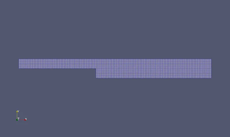
The mesh generated for case 1 with a grading factor of 1:
This image represents that the mesh is uniform and the cells are equally distributed throughout the domain with no refinement.
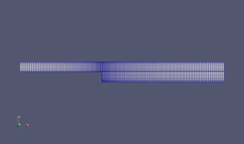
The mesh generated for case 2 with a grading factor of 0.2 and refined close to the walls:
This image represents that the mesh is refined close to the walls compared to the free-stream region and there is a gradual decrease in the cell size while moving towards the wall.
Code for blockMeshDict for case 1 with no Grading factor:
/*--------------------------------*- C++ -*----------------------------------*\
  =========                 |
  \\      /  F ield         | OpenFOAM: The Open Source CFD Toolbox
   \\    /   O peration     | Website:  https://openfoam.org
    \\  /    A nd           | Version:  8
     \\/     M anipulation  |
\*---------------------------------------------------------------------------*/
FoamFile
{
    version     2.0;
    format      ascii;
    class       dictionary;
    object      blockMeshDict;
}
// * * * * * * * * * * * * * * * * * * * * * * * * * * * * * * * * * * * * * //

convertToMeters 1;

vertices
(
    (0 0 0)
    (0.08 0 0)
    (0.08 0.005 0)
    (0 0.005 0)
    (0.08 0.01 0)
    (0 0.01 0)
    (0.2 0.01 0)
    (0.2 0.005 0)
    (0.2 0 0)
    (0.2 -0.01 0)
    (0.08 -0.01 0)

    (0 0 0.001)
    (0.08 0 0.001)
    (0.08 0.005 0.001)
    (0 0.005 0.001)
    (0.08 0.01 0.001)
    (0 0.01 0.001)
    (0.2 0.01 0.001)
    (0.2 0.005 0.001)
    (0.2 0 0.001)
    (0.2 -0.01 0.001)
    (0.08 -0.01 0.001)
);

blocks
(
    hex (0 1 2 3 11 12 13 14)
    (80 5 1)
    simpleGrading (1 1 1)

    hex (3 2 4 5 14 13 15 16)
    (80 5 1)
    simpleGrading (1 1 1)

    hex (1 8 7 2 12 19 18 13)
    (120 5 1)
    simpleGrading (1 1 1)

    hex (2 7 6 4 13 18 17 15)
    (120 5 1)
    simpleGrading (1 1 1)

    hex (10 9 8 1 21 20 19 12)
    (120 10 1)
    simpleGrading (1 1 1)

);


boundary
(
    inlet
    {
        type patch;
        faces
        (
            (0 11 14 3)
            (3 14 16 5)
        );
    }
    outlet
    {
        type patch;
        faces
        (
            (9 8 19 20)
            (8 7 18 19)
            (7 6 17 18)
        );
    }
    wall
    {
        type wall;
        faces
        (
            (5 16 15 4)
            (4 15 17 6)
            (10 21 12 1)
            (0 1 12 11)
            (10 9 20 21)
        );
    }
    frontAndBack
    {
        type empty;
        faces
        (
            (11 12 13 14)
            (14 13 15 16)
            (21 20 19 12)
            (12 19 18 13)
            (13 18 17 15)
            (0 3 2 1)
            (3 5 4 2)
            (2 4 6 7)
            (1 2 7 8)
            (10 1 8 9)
        );
    }
);

// ************************************************************************* //
Code for blockMeshDict for case 2 with Grading factor of 0.2:
/*--------------------------------*- C++ -*----------------------------------*\
  =========                 |
  \\      /  F ield         | OpenFOAM: The Open Source CFD Toolbox
   \\    /   O peration     | Website:  https://openfoam.org
    \\  /    A nd           | Version:  8
     \\/     M anipulation  |
\*---------------------------------------------------------------------------*/
FoamFile
{
    version     2.0;
    format      ascii;
    class       dictionary;
    object      blockMeshDict;
}
// * * * * * * * * * * * * * * * * * * * * * * * * * * * * * * * * * * * * * //

convertToMeters 1;

vertices
(
    (0 0 0)
    (0.08 0 0)
    (0.08 0.005 0)
    (0 0.005 0)
    (0.08 0.01 0)
    (0 0.01 0)
    (0.2 0.01 0)
    (0.2 0.005 0)
    (0.2 0 0)
    (0.2 -0.01 0)
    (0.08 -0.01 0)

    (0 0 0.001)
    (0.08 0 0.001)
    (0.08 0.005 0.001)
    (0 0.005 0.001)
    (0.08 0.01 0.001)
    (0 0.01 0.001)
    (0.2 0.01 0.001)
    (0.2 0.005 0.001)
    (0.2 0 0.001)
    (0.2 -0.01 0.001)
    (0.08 -0.01 0.001)
);

blocks
(
    hex (0 1 2 3 11 12 13 14)
    (80 5 1)
    simpleGrading (0.2 5 1)

    hex (3 2 4 5 14 13 15 16)
    (80 5 1)
    simpleGrading (0.2 0.2 1)

    hex (1 8 7 2 12 19 18 13)
    (120 5 1)
    simpleGrading (5 5 1)

    hex (2 7 6 4 13 18 17 15)
    (120 5 1)
    simpleGrading (5 0.2 1)

    hex (10 9 8 1 21 20 19 12)
    (120 10 1)
    simpleGrading (5 5 1)

);


boundary
(
    inlet
    {
        type patch;
        faces
        (
            (0 11 14 3)
            (3 14 16 5)
        );
    }
    outlet
    {
        type patch;
        faces
        (
            (9 8 19 20)
            (8 7 18 19)
            (7 6 17 18)
        );
    }
    wall
    {
        type wall;
        faces
        (
            (5 16 15 4)
            (4 15 17 6)
            (10 21 12 1)
            (0 1 12 11)
            (10 9 20 21)
        );
    }
    frontAndBack
    {
        type empty;
        faces
        (
            (11 12 13 14)
            (14 13 15 16)
            (21 20 19 12)
            (12 19 18 13)
            (13 18 17 15)
            (0 3 2 1)
            (3 5 4 2)
            (2 4 6 7)
            (1 2 7 8)
            (10 1 8 9)
        );
    }
);

// ************************************************************************* //
Boundary and initial conditions definition:
The following boundary conditions were defined:
- Velocity of 1m/s at the inlet
- Pressure outlet at atmospheric pressure
- No-slip BC at the top, bottom, and sidewalls
- Front and back faces were defined as empty
Code for the BCs:
U:
/*--------------------------------*- C++ -*----------------------------------*\
  =========                 |
  \\      /  F ield         | OpenFOAM: The Open Source CFD Toolbox
   \\    /   O peration     | Website:  https://openfoam.org
    \\  /    A nd           | Version:  8
     \\/     M anipulation  |
\*---------------------------------------------------------------------------*/
FoamFile
{
    version     2.0;
    format      ascii;
    class       volVectorField;
    object      U;
}
// * * * * * * * * * * * * * * * * * * * * * * * * * * * * * * * * * * * * * //

dimensions      [0 1 -1 0 0 0 0];

internalField   uniform (0 0 0);

boundaryField
{
    inlet
    {
        type            fixedValue;
        value           uniform (1 0 0);
    }

    outlet
    {
        type            zeroGradient;
    }

    wall
    {
        type            noSlip;
    }

    frontAndBack
    {
        type            empty;
    }
}

// ************************************************************************* //
p:
/*--------------------------------*- C++ -*----------------------------------*\
  =========                 |
  \\      /  F ield         | OpenFOAM: The Open Source CFD Toolbox
   \\    /   O peration     | Website:  https://openfoam.org
    \\  /    A nd           | Version:  8
     \\/     M anipulation  |
\*---------------------------------------------------------------------------*/
FoamFile
{
    version     2.0;
    format      ascii;
    class       volScalarField;
    object      p;
}
// * * * * * * * * * * * * * * * * * * * * * * * * * * * * * * * * * * * * * //

dimensions      [0 2 -2 0 0 0 0];

internalField   uniform 0;

boundaryField
{
    inlet
    {
        type            zeroGradient;
    }

    outlet
    {
        type            fixedValue;
        value		 uniform 0;
    }

    wall
    {
        type            zeroGradient;
    }

    frontAndBack
    {
        type            empty;
    }
}

// ************************************************************************* //
Numerical/Simulation settings:
The numerical and simulation setting for the simulation is set in the controlDict file, and the fvSchemes and fvSolution file have been left unaltered wiht the default parameters. icoFoam solver has the capacity to perform the simulation of transient-incompressible-laminar-viscous flow and hence this solver is used in this project. The controlDict file defines what solver will be used here icoFoam, time step for the simulation and total run time inclusive of other paramteres relevant for running and printing/storing the result data.
conrolDict file includes:
/*--------------------------------*- C++ -*----------------------------------*\
  =========                 |
  \\      /  F ield         | OpenFOAM: The Open Source CFD Toolbox
   \\    /   O peration     | Website:  https://openfoam.org
    \\  /    A nd           | Version:  8
     \\/     M anipulation  |
\*---------------------------------------------------------------------------*/
FoamFile
{
    version     2.0;
    format      ascii;
    class       dictionary;
    location    "system";
    object      controlDict;
}
// * * * * * * * * * * * * * * * * * * * * * * * * * * * * * * * * * * * * * //

application     icoFoam;

startFrom       startTime;

startTime       0;

stopAt          endTime;

endTime         0.75;

deltaT          0.0005;

writeControl    timeStep;

writeInterval   40;

purgeWrite      0;

writeFormat     ascii;

writePrecision  6;

writeCompression off;

timeFormat      general;

timePrecision   6;

runTimeModifiable true;

functions
{
	#includeFunc residuals;
}


// ************************************************************************* //
Results:
Case 1: with no grading
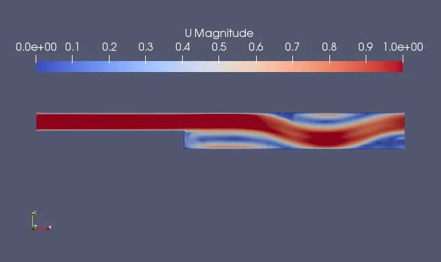
The velocity magnitude plot at the final time-step depicts the variation of fluid flow velocity through the domain, also recirculation zones are observed close to the backward-facing step and close to the outlet. These recirculation zones have been captured by the solver and displayed in the image.
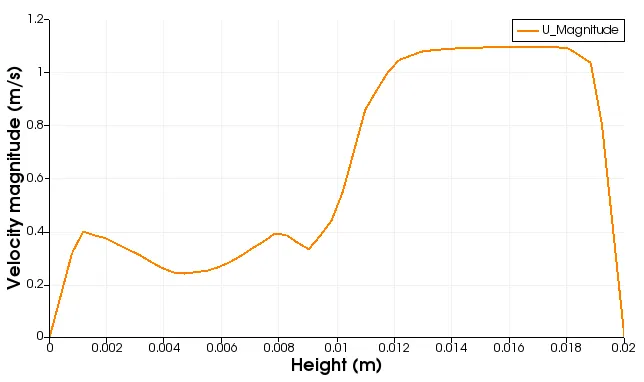
Velocity magnitude variation with respect to the height of the domain at a particular location here, at x=0.85m which is close to the step but towards the right. This plot shows that the velocity is high close to the topwall and lower close to the step wall and the bottom wall.
Case 2: with mesh grading factor of 0.2
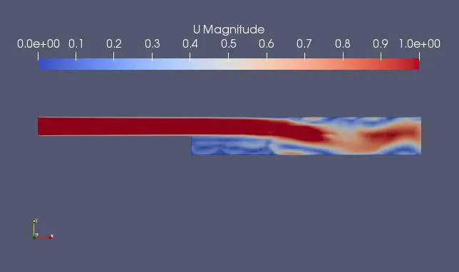
The velocity magnitude plot at the final time-step depicts the variation of fluid flow velocity through the domain, also recirculation zones are observed close to the backward-facing step and close to the outlet. These recirculation zones have been captured by the solver and displayed in the image. Along with the recirculation there exists some intermixing that gives to different bands of velocity and is obervably captured in this case due to the better mesh.
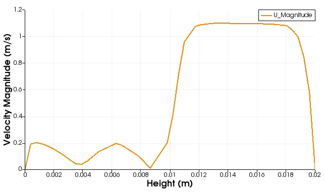
Velocity magnitude variation with respect to the height of the domain at a particular location here, at x=0.85m which is close to the step but towards the right. This plot shows that the velocity is high close to the topwall and lower close to the step wall and the bottom wall. As expected from the previous contour the variation of velocity close to the backward-facing step is captured better in this case compared to the previous case and the constant velocity region from y=0.012 to 0.018 which is also observed in the above contour are a thick band is well represented in this plot as a flat curve and steep variations towards the left and right of this region.
Conlusion:
From the above contours and plots for both the cases it is clearly understood that the case with mesh grading help provide better results as the mesh is refined close to the wall and hence helps in capturing the velocity variation due to the boundary layer formation. Especially in this type of flow problem where no-slip walls exists and this means that the velocity close to the wall is almost 0m/s and the velocity in the freestream region is close to the inlet velocity. This increase/decrease in velocity variation from 0-1m/s as moving from the wall to the freestream region must be calculated and captured accurately as it plays a huge role in high speed flows or applications. Hence the growth factor/grading plays a crucial role in the simulation and is essential for meshing.