Week 8 - Simulation of a backward facing step in OpenFOAM
AIM
Simulate an incompressible-laminar-viscous transient flow through the backward-facing step geometry.
Perform 2 case studies as described below and compare the results.
Case 1 - Simulate the flow without using any grading factor (i.e., GF = 1)
Case 2 - Simulate the flow with a grading factor of 0.2. The cells should be finer near the walls (including the step wall).
THEORY
Incompressible flow is the type of flow where the change in density of the fluid wrt time and distance is zero.
Laminar flow is the type of flow in which the fluid tends to flow in infinitesimal parallel layers with no disruption between them. In laminar flows, fluid layers slide in parallel, with no eddies, swirls, or currents normal to the flow.
Viscous flow occurs when the viscosity of the fluid is equal to the inertial forces of the fluid. This internal friction between fluid particles (viscosity) has its effects on the boundary layer formation and the fluid closest to the boundary wall moves the slowest (or is at rest) with the velocity increasing moving further away from the wall.
Based on the viscosity the fluid further gets differentiated based on the comparison of the rate of change of viscous shear stress to the rate of deformation. This is Newtonian and Non-Newtonian fluid. In Newtonian fluid, the viscous stress arising from its flow, at every point, is linearly correlated to the local strain rate - the rate of change of its deformation over time.
In a transient flow simulation, the flow reaches a steady state after a period of time.
In this case of Backward Facing Step, after 1.5 seconds the follow becomes a steady state flow. The flow is captured up to 2 seconds.
SIMULATION
1. Solver selection
The solver is decided based on the type of flow to be simulated. We first open the OpenFOAM Tutorials folder to select the incompressible flow option. This is executed with the command cd $FOAM_TUTORIALS.

In the incompressible flow section, icoFoam is selected. This solver is the most suitable to solve the incoompressible-laminar-viscous flow with the transient simulation.

In the icoFoam section, cavity is selected. Under the cavity section, again cavity is selected as we are simulating the flow in cavity. However, this cavity geometry needs to redefined as mentioned in the Geometry in the problem statement.

2. Geometry
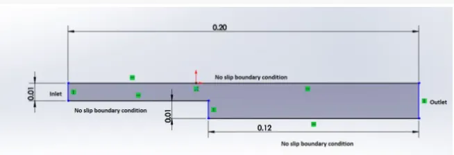
In the above geometry we can see that, the inlet is at the right and outlet at the left. The walls have a no-slip boundary condition.
To edit the geometry the file is copied to RUN folder named $FOAM_RUN. This folder helps to make changes and edits in boundary and mesh conditions as required without disturbing the main folder. The cavity is renamed as backward_step_test.
The geometry is updated in the backward_step_test file. On opening the file, in the system folder, blockMeshDict file is selected.
/*--------------------------------*- C++ -*----------------------------------*\
  =========                 |
  \\      /  F ield         | OpenFOAM: The Open Source CFD Toolbox
   \\    /   O peration     | Website:  https://openfoam.org
    \\  /    A nd           | Version:  10
     \\/     M anipulation  |
\*---------------------------------------------------------------------------*/
FoamFile
{
    format      ascii;
    class       dictionary;
    object      blockMeshDict;
}
// * * * * * * * * * * * * * * * * * * * * * * * * * * * * * * * * * * * * * //

convertToMeters 0.01;

vertices
(
   /* Vertices for the backside of the blocks */
    (0 0 0)
    (8 0 0)
    (8 0.5 0)
    (0 0.5 0)
    (8 1 0)
    (0 1 0)
    (20 1 0)
    (20 0.5 0)
    (20 0 0)
    (20 -1 0)
    (8 -1 0)

   /* Vertices for the frontside of the blocks */
    (0 0 0.6)
    (8 0 0.6)
    (8 0.5 0.6)
    (0 0.5 0.6)
    (8 1 0.6)
    (0 1 0.6)
    (20 1 0.6)
    (20 0.5 0.6)
    (20 0 0.6)
    (20 -1 0.6)
    (8 -1 0.6)
);

blocks
(
    hex (0 1 2 3 11 12 13 14) (80 5 1) simpleGrading (1 1 1)
    hex (3 2 4 5 14 13 15 16) (80 5 1) simpleGrading (1 1 1)
    hex (2 7 6 4 13 18 17 15) (120 5 1) simpleGrading (1 1 1)
    hex (1 8 7 2 12 19 18 13) (120 5 1) simpleGrading (1 1 1)
    hex (10 9 8 1 21 20 19 12) (120 10 1) simpleGrading (1 1 1)
);
Based on the geomtery specifications mentioned, the geometry is edited in the blockMeshDict file by specifying the vertices.
In this case, we define the vertices in the anti-clockwise order for 2 sides (front and back) with the length in z -direction being 0.006.
3. Meshing
Mesh specification
- Number of cells along the x direction (longer dimension) = 200
- Number of cells along the longer y direction = 20
In this problem we simulate the flow with two types of meshing.
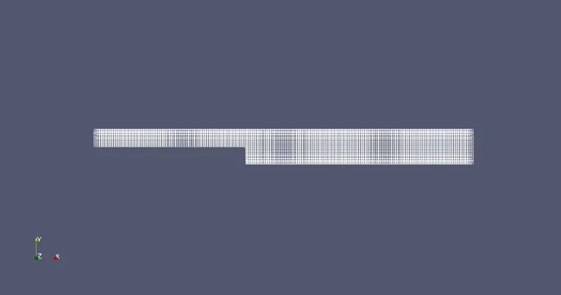
The first one is the general mesh with specifications mentioned. There is no grading in the mesh and the grading factor (G.F.) = 1
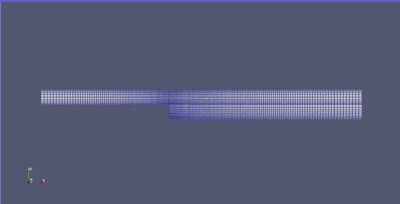
The second one is a refined mesh with biasing on one side with the same specifications as mentioned above. The mesh is more refined on the walls than the centre. The G.F. = 0.2
*Grading Factor (G.F.) = (size of end cell) / (size of starting cell)
In the blockMeshDict file, while defining the blocks, the simpleGrading is also defined.
Case 1 - G.F. = 0
blocks
(
    hex (0 1 2 3 11 12 13 14) (80 5 1) simpleGrading (1 1 1)
    hex (3 2 4 5 14 13 15 16) (80 5 1) simpleGrading (1 1 1)
    hex (2 7 6 4 13 18 17 15) (120 5 1) simpleGrading (1 1 1)
    hex (1 8 7 2 12 19 18 13) (120 5 1) simpleGrading (1 1 1)
    hex (10 9 8 1 21 20 19 12) (120 10 1) simpleGrading (1 1 1)
);
Result of the mesh is as below.
Case 2 - G.F. = 0.2
blocks
(
    hex (0 1 2 3 11 12 13 14) (80 5 1) simpleGrading (0.2 5 1)
    hex (3 2 4 5 14 13 15 16) (80 5 1) simpleGrading (0.2 0.2 1)
    hex (2 7 6 4 13 18 17 15) (120 5 1) simpleGrading (5 0.2 1)
    hex (1 8 7 2 12 19 18 13) (120 5 1) simpleGrading (5 5 1)
    hex (10 9 8 1 21 20 19 12) (120 10 1) simpleGrading (5 5 1)
);
Here it can be noticed, unlike the first case, the simpleGrading is defined based on the specifications in the problem statement. The walls have more refined mesh as compared to the centres as shown below. The step wall is also refined as specified.
To apply the mesh edits, the blockMesh command inside the backward_step_test directory is used.
4. Boundary conditions and Initial conditions
We define the boundary conditions by patching the faces and the walls as specified. These edits are also done in the blockMeshDict file.
The blockMeshDict files are as follows for the two cases.
Case 1 - G.F. = 0
/*--------------------------------*- C++ -*----------------------------------*\
  =========                 |
  \\      /  F ield         | OpenFOAM: The Open Source CFD Toolbox
   \\    /   O peration     | Website:  https://openfoam.org
    \\  /    A nd           | Version:  10
     \\/     M anipulation  |
\*---------------------------------------------------------------------------*/
FoamFile
{
    format      ascii;
    class       dictionary;
    object      blockMeshDict;
}
// * * * * * * * * * * * * * * * * * * * * * * * * * * * * * * * * * * * * * //

convertToMeters 0.01;

vertices
(
   /* Vertices for the backside of the blocks */
    (0 0 0)
    (8 0 0)
    (8 0.5 0)
    (0 0.5 0)
    (8 1 0)
    (0 1 0)
    (20 1 0)
    (20 0.5 0)
    (20 0 0)
    (20 -1 0)
    (8 -1 0)

   /* Vertices for the frontside of the blocks */
    (0 0 0.6)
    (8 0 0.6)
    (8 0.5 0.6)
    (0 0.5 0.6)
    (8 1 0.6)
    (0 1 0.6)
    (20 1 0.6)
    (20 0.5 0.6)
    (20 0 0.6)
    (20 -1 0.6)
    (8 -1 0.6)
);

blocks
(
    hex (0 1 2 3 11 12 13 14) (80 5 1) simpleGrading (1 1 1)
    hex (3 2 4 5 14 13 15 16) (80 5 1) simpleGrading (1 1 1)
    hex (2 7 6 4 13 18 17 15) (120 5 1) simpleGrading (1 1 1)
    hex (1 8 7 2 12 19 18 13) (120 5 1) simpleGrading (1 1 1)
    hex (10 9 8 1 21 20 19 12) (120 10 1) simpleGrading (1 1 1)
);

boundary
(
    inlet
    {
        type patch;
        faces
        (
            (0 11 14 3)
            (3 14 16 5)
        );
    }
    outlet
    {
        type patch;
        faces
        (
            (9 8 19 20)
            (8 7 18 19)
            (7 6 17 18)
        );
    }
    frontAndBack
    {
        type empty;
        faces
        (
            (0 3 2 1)
            (3 5 4 2)
            (2 4 6 7)
            (1 2 7 8)
            (10 1 8 9)

            (11 12 13 14)
            (14 13 15 16)
            (13 18 17 15)
            (12 19 18 13)
            (21 20 19 12)
        );
    }
    fixedWalls
    {
        type wall;
        faces
        (
            (5 16 15 4)
            (0 1 12 11)
            (4 15 17 6)
            (10 9 20 21)
            (10 21 12 1)
         );
    }
);
 mergePatchPairs
 (
 );

// ************************************************************************* //
Case 2 - G.F. = 0.2
/*--------------------------------*- C++ -*----------------------------------*\
  =========                 |
  \\      /  F ield         | OpenFOAM: The Open Source CFD Toolbox
   \\    /   O peration     | Website:  https://openfoam.org
    \\  /    A nd           | Version:  10
     \\/     M anipulation  |
\*---------------------------------------------------------------------------*/
FoamFile
{
    format      ascii;
    class       dictionary;
    object      blockMeshDict;
}
// * * * * * * * * * * * * * * * * * * * * * * * * * * * * * * * * * * * * * //

convertToMeters 0.01;

vertices
(
    /* Vertices for the backside of the blocks */
    (0 0 0)
    (8 0 0)
    (8 0.5 0)
    (0 0.5 0)
    (8 1 0)
    (0 1 0)
    (20 1 0)
    (20 0.5 0)
    (20 0 0)
    (20 -1 0)
    (8 -1 0)

   /* Vertices for the frontside of the blocks */
    (0 0 0.6)
    (8 0 0.6)
    (8 0.5 0.6)
    (0 0.5 0.6)
    (8 1 0.6)
    (0 1 0.6)
    (20 1 0.6)
    (20 0.5 0.6)
    (20 0 0.6)
    (20 -1 0.6)
    (8 -1 0.6)
);

blocks
(
    hex (0 1 2 3 11 12 13 14) (80 5 1) simpleGrading (0.2 5 1)
    hex (3 2 4 5 14 13 15 16) (80 5 1) simpleGrading (0.2 0.2 1)
    hex (2 7 6 4 13 18 17 15) (120 5 1) simpleGrading (5 0.2 1)
    hex (1 8 7 2 12 19 18 13) (120 5 1) simpleGrading (5 5 1)
    hex (10 9 8 1 21 20 19 12) (120 10 1) simpleGrading (5 5 1)
);

boundary
(
    inlet
    {
        type patch;
        faces
        (
            (0 11 14 3)
            (3 14 16 5)
        );
    }
    outlet
    {
        type patch;
        faces
        (
            (9 8 19 20)
            (8 7 18 19)
            (7 6 17 18)
        );
    }
    frontAndBack
    {
        type empty;
        faces
        (
            (0 3 2 1)
            (3 5 4 2)
            (2 4 6 7)
            (1 2 7 8)
            (10 1 8 9)

            (11 12 13 14)
            (14 13 15 16)
            (13 18 17 15)
            (12 19 18 13)
            (21 20 19 12)
        );
    }
    fixedWalls
    {
        type wall;
        faces
        (
            (5 16 15 4)
            (0 1 12 11)
            (4 15 17 6)
            (10 9 20 21)
            (10 21 12 1)
         );
    }
);
 mergePatchPairs
 (
 );

// ************************************************************************* //
For the initial conditions to be defined, the Velocity (U) and Pressure (p) at the inlet at t=0 needs to be defined. Moreover, the time step is defined in the controlDict file in the system section of the backward_step_test folder.
Note that the velocity(U) and the time steps are different for both the cases. This is due to the aggressive change in element length (caused due to grading), which in turn causes the Courant No. to increase above 1. To maintain the Courant No. below 1, both the velocity and time step values are modified accordingly.
The controlDict, p, and U files for both the cases are as below.
Case 1 - G.F. = 0
a. controlDict
/*--------------------------------*- C++ -*----------------------------------*\
  =========                 |
  \\      /  F ield         | OpenFOAM: The Open Source CFD Toolbox
   \\    /   O peration     | Website:  https://openfoam.org
    \\  /    A nd           | Version:  10
     \\/     M anipulation  |
\*---------------------------------------------------------------------------*/
FoamFile
{
    format      ascii;
    class       dictionary;
    location    "system";
    object      controlDict;
}
// * * * * * * * * * * * * * * * * * * * * * * * * * * * * * * * * * * * * * //

application     icoFoam;

startFrom       startTime;

startTime       0;

stopAt          endTime;

endTime         3;

deltaT          0.01;

writeControl    timeStep;

writeInterval   1;

purgeWrite      0;

writeFormat     ascii;

writePrecision  6;

writeCompression off;

timeFormat      general;

timePrecision   6;

runTimeModifiable true;


// ************************************************************************* //
b. Pressure (p)
/*--------------------------------*- C++ -*----------------------------------*\
  =========                 |
  \\      /  F ield         | OpenFOAM: The Open Source CFD Toolbox
   \\    /   O peration     | Website:  https://openfoam.org
    \\  /    A nd           | Version:  10
     \\/     M anipulation  |
\*---------------------------------------------------------------------------*/
FoamFile
{
    format      ascii;
    class       volScalarField;
    object      p;
}
// * * * * * * * * * * * * * * * * * * * * * * * * * * * * * * * * * * * * * //

dimensions      [0 2 -2 0 0 0 0];

internalField   uniform 0;

boundaryField
{
    inlet
    {
        type            zeroGradient;
    }
    outlet
    {
        type            fixedValue;
        value           uniform 0;
    }
    fixedWalls
    {
        type            zeroGradient;
    }

    frontAndBack
    {
        type            empty;
    }
}

// ************************************************************************* //
c. Velocity(U)
/*--------------------------------*- C++ -*----------------------------------*\
  =========                 |
  \\      /  F ield         | OpenFOAM: The Open Source CFD Toolbox
   \\    /   O peration     | Website:  https://openfoam.org
    \\  /    A nd           | Version:  10
     \\/     M anipulation  |
\*---------------------------------------------------------------------------*/
FoamFile
{
    format      ascii;
    class       volVectorField;
    object      U;
}
// * * * * * * * * * * * * * * * * * * * * * * * * * * * * * * * * * * * * * //

dimensions      [0 1 -1 0 0 0 0];

internalField   uniform (0 0 0);

boundaryField
{
    inlet
    {
        type            fixedValue;
        value           uniform (0.0667 0 0);
    }
    outlet
    {
        type            zeroGradient;
    }

    fixedWalls
    {
        type            noSlip;
    }

    frontAndBack
    {
        type            empty;
    }
}

// ************************************************************************* //
Case 2 - G.F. = 0.2
a. controlDict
/*--------------------------------*- C++ -*----------------------------------*\
  =========                 |
  \\      /  F ield         | OpenFOAM: The Open Source CFD Toolbox
   \\    /   O peration     | Website:  https://openfoam.org
    \\  /    A nd           | Version:  10
     \\/     M anipulation  |
\*---------------------------------------------------------------------------*/
FoamFile
{
    format      ascii;
    class       dictionary;
    location    "system";
    object      controlDict;
}
// * * * * * * * * * * * * * * * * * * * * * * * * * * * * * * * * * * * * * //

application     icoFoam;

startFrom       startTime;

startTime       0;

stopAt          endTime;

endTime         2;

deltaT          0.0001;

writeControl    timeStep;

writeInterval   10;

purgeWrite      0;

writeFormat     ascii;

writePrecision  6;

writeCompression off;

timeFormat      general;

timePrecision   6;

runTimeModifiable true;


// ************************************************************************* //
b. Pressure (p)
/*--------------------------------*- C++ -*----------------------------------*\
  =========                 |
  \\      /  F ield         | OpenFOAM: The Open Source CFD Toolbox
   \\    /   O peration     | Website:  https://openfoam.org
    \\  /    A nd           | Version:  10
     \\/     M anipulation  |
\*---------------------------------------------------------------------------*/
FoamFile
{
    format      ascii;
    class       volScalarField;
    object      p;
}
// * * * * * * * * * * * * * * * * * * * * * * * * * * * * * * * * * * * * * //

dimensions      [0 2 -2 0 0 0 0];

internalField   uniform 0;

boundaryField
{
    inlet
    {
        type            zeroGradient;
    }
    outlet
    {
        type            fixedValue;
        value           uniform 0;
    }
    fixedWalls
    {
        type            zeroGradient;
    }

    frontAndBack
    {
        type            empty;
    }
}


// ************************************************************************* //
c. Velocity(U)
/*--------------------------------*- C++ -*----------------------------------*\
  =========                 |
  \\      /  F ield         | OpenFOAM: The Open Source CFD Toolbox
   \\    /   O peration     | Website:  https://openfoam.org
    \\  /    A nd           | Version:  10
     \\/     M anipulation  |
\*---------------------------------------------------------------------------*/
FoamFile
{
    format      ascii;
    class       volVectorField;
    object      U;
}
// * * * * * * * * * * * * * * * * * * * * * * * * * * * * * * * * * * * * * //

dimensions      [0 1 -1 0 0 0 0];

internalField   uniform (0 0 0);

boundaryField
{
    inlet
    {
        type            fixedValue;
        value           uniform (0.001 0 0);
    }
    outlet
    {
        type            zeroGradient;
    }

    fixedWalls
    {
        type            noSlip;
    }

    frontAndBack
    {
        type            empty;
    }
}

// ************************************************************************* //
To run the simulation the icoFoam command is used in the backward_step_test directory.
5. Results and Discussion
The results for the flow in two different cases are shown below. The paraFoam command is used to open ParaView.

Case 1 - G.F. = 0
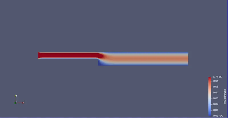
In the above image, it can be seen that the fluid flows down the step. However, the at the step the total velocity 0 due to the formation of eddies.
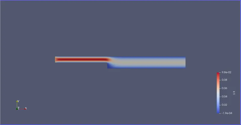
In the above image, it can be seen the x component of velocity (Ux) is negative near the step walls showing the formation of eddies.
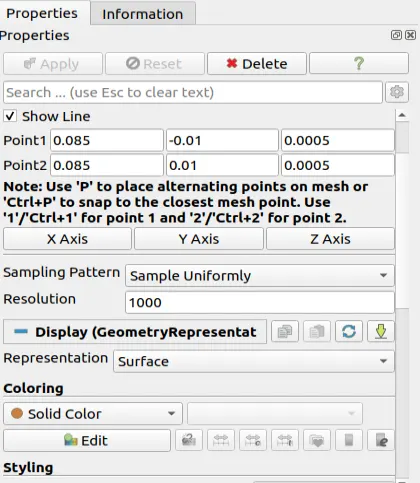
To plot the graph, the Line Parameters option is selected as shown below. The velocity observed here is at x= 0.085.The graph gives the variation of velocity along the y axis line at x =0.085.
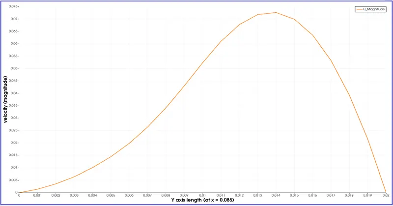
The velocity profile above shows the variation of the magnitude of velocity near the step wall (at x=0.085)
Case 2 - G.F. = 0.2
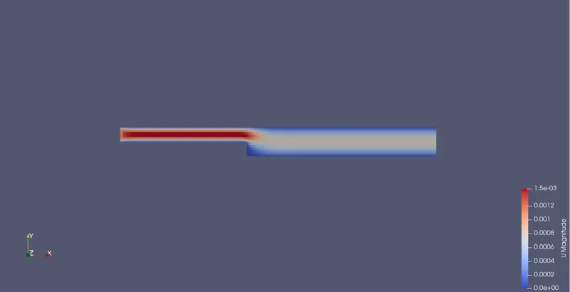
As seen in the above image, the velocity profile is similar to the profile with GF = 0. However, it can been observed that velocity profile near the walls is better defined and the profile at the centre is not. To get a uniformly defined profile the number of divisions have to increased. This would reduce the element length and hence capture the velocity profile in a more detailed manner.
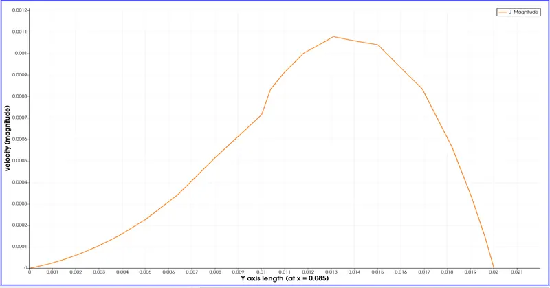
It can be observed from the above graph, that the velocity at the center distorts due to the increase in element size. This can be avoided by increasing the number of divisions that would help capture the velocity profile better in turn making the graph more curved rather than distorted.
By changing the simple grading factor from the value of 0.2 to 1 the mesh becomes finer and the solution becomes very accurate.
Overall the change in the size of simple grading factor (mesh size) the results remains the same as approximately.
The execution time is lower for lower meshing grading factor.