Week 3 Challenge : CFD meshing on Turbocharger
AIM
- To remove the geometrical errors and perform a Topology cleanup in the Turbocharger geometry.
- To create and assign PIDs and perform Surface Mesh as per assigned target lengths for PIDs
- Perform Volume Meshing for the required volumes for the assigned PIDs.
THEORY
A Turbocharger is a mechanical device used primarily in IC Engines to compress the incoming air more with the help of exhaust gas. When air is compressed the oxygen molecules are packed closer together. This increase in the air means that more fuel can be added for the same size naturally aspirated engine. This then generates increased mechanical power and overall efficiency improvement of the combustion process. Therefore, the engine size can be reduced for a turbocharged engine leading to better packaging, weight-saving benefits, and overall improved fuel economy.
In the below procedure of meshing, the procedure will consist of three main procedures.
1. Overlapping Face Deletion and Face Addition (Geometry Error Cleanup)
It is the most basic and primary step to have a complete geometry, thus helping in defining the Property ID (PID). The overlapping surfaces in the geometry need to be identified and removed before any addition of a new surface in the same place. The identification of overlapped(extraneous) surfaces is done by observing the uniformity between the color codes of PIDs and actual surfaces. The surface addition can be carried out by numerous methods. ANSA primarily provides the addition of face surfaces through COONS, FITTED, PLANAR, and EXISTING SURFACE. Apart from these, ANSA also provides a feature called FILL HOLE under the CONS bar in the TOPO Menu. These tools help surface addition in numerous missing spaces thus completing the geometry surface.
2. PID definition and Intersection Error removal (Topo Cleanup)
PID definition is an important aspect as it helps define the surfaces and further their mesh properties in complex geometries. It is also crucial as and when the models are exported for CFD analysis. Following the definitions, the intersections caused by the surfaces are ought to be removed without which CFD analysis is not possible. The surface intersections are removed using the INTERSECT tool in the FACES bar of the TOPO Menu. The INTERSECT tool lets us select the two surfaces causing intersections and eliminate the unnecessary surfaces.
3. Setting of Mesh parameters
Setting mesh parameters include setting up mesh element length and also mesh quality criteria in complex geometries. Here, the design will consist of different mesh sizes for different parts of the geometry. In an industry scenario, it becomes extremely crucial to determine the mesh size based on the simulation to be carried out.
The mesh parameters assigned as per PIDs are
- Blade stage-1 = 1 mm
- Blade stage-2 = 1 mm
- Impeller = 2 mm
- Shaft rotor = 1 mm
- Turbo casing = 5 mm
- Compressor casing = 5 mm
- Inlet casing cover = 5 mm
PROCEDURE
On opening the ANSA launcher, the CFD layout is used along the performance mode 3 for efficient performance.
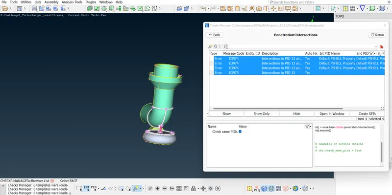
On importing the geometry, we can see both the external overlapping surfaces and intersections, evidently.
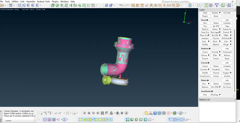
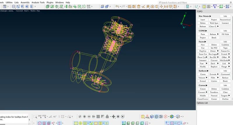
The pink surface is the largest overlapping surface along with some internal small overlapping surfaces that will be observed ahead. The red COONS are evidently visible in the wireframe.
In this geometry, the Geometry Error Cleanup and Topo Cleanup are parallelly carried out.
I. Geometry Error and Topo Cleanup
1. Compressor Casing
- The major extra overlapped surface is identified.
- The surface is then deleted through Faces > Delete, and then select the surface to be deleted. (Middle-click scroll button after selection of the surface)
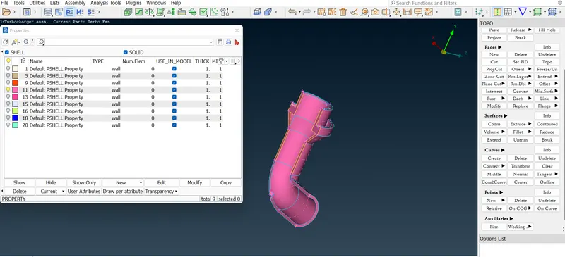
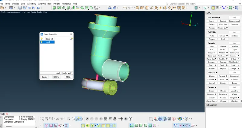
- After deleting the overlapped surface, a new surface is made by selecting Faces > New > Coons. The coons surrounding the surface are selected, thus helping the tool detect the empty surface. The surface of the lower side of the Compressor Casing is made.
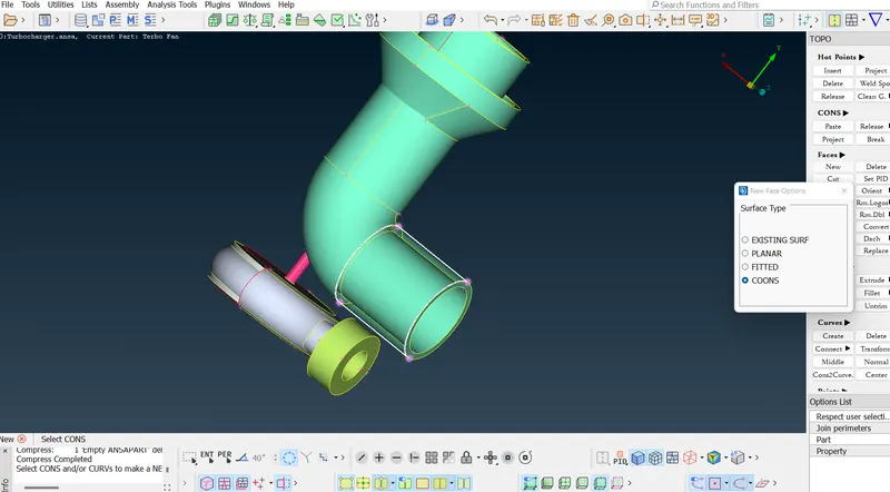
- On viewing in wireframe, an intersection error is detected in the neck of the Compressor Casing. This is eliminated by selecting Faces > Intersect under the TOPO menu. After this, the two intersecting surfaces are selected and the excessive surfaces are removed as seen in the below images.
Note that the inner curved surface on the neck is causing the intersection, and hence, is deleted.
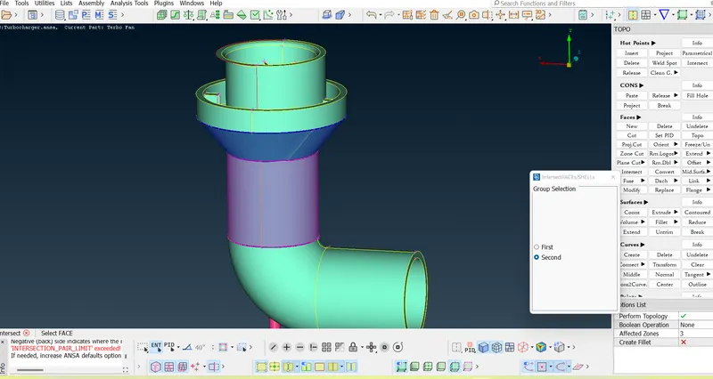
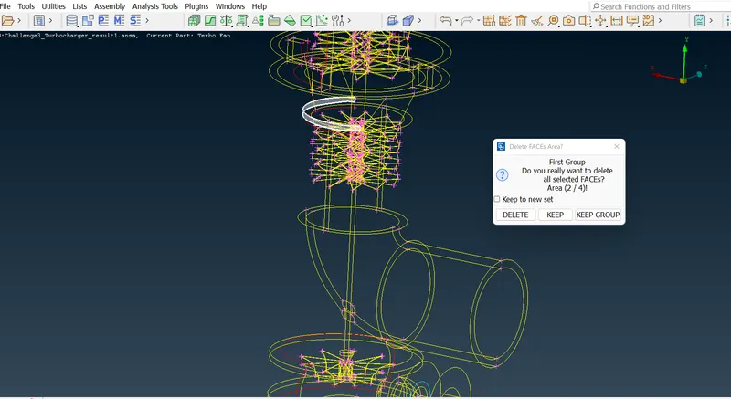
- Further, it is noticed that the neck of the Compressor Casing doesn't consist of uniform COONS. This is addressed by making a new COON by selecting Faces > Cut. A new COON is cut across the surface, thus making the curve uniform.
- After the creation of the COON, the surfaces are deleted to make a new uniform surface over the same region.
- The new surface is made by selecting Faces > New > COONS.
Note that the extra Hot Points (caused by the construction of new COON) are deleted before any addition of surfaces.
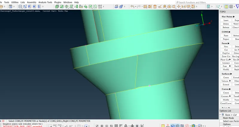
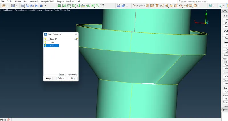
The deletion of extra Hot Points can be seen in the following image. It is deleted by selecting Hot Points > Delete > Selecting the extra Hot Points.
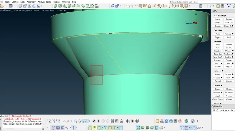
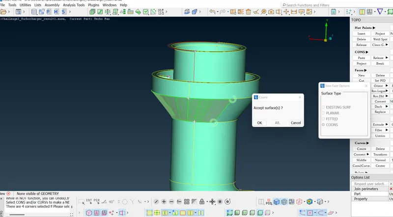
- When further observed, Red COONS just above the neck of the Compressor Casing are found. This is due the missing surface on one half of the Casing.
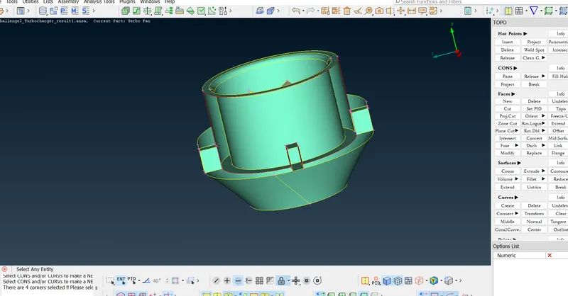
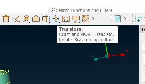
- The Transform Tool is used to create a new COON. This tool enables the construction of COONS in areas with no surface. This is done by selecting Curves > Transform. The direction of the transformation is selected based on the curvature of the COON required.
- With the newly constructed COON, new surfaces are added and overlapping surfaces are deleted.
- Finally, the COON constructed is deleted as it comes out to be an extra CURVE. It is done by selecting Curves > Delete. The curve to be deleted is selected.
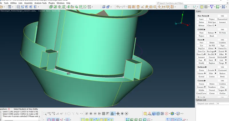
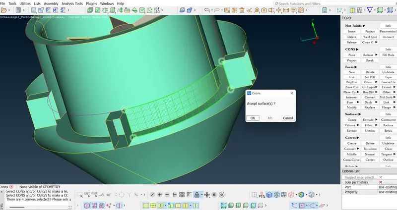
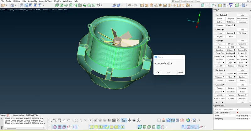
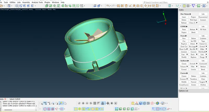
Note for refinement of the new surfaces, the Resolution can be set using the Perimeter option under Faces or under the Settings menu. This refines the curves and eliminates any pixelation.
2. Turbine Casing
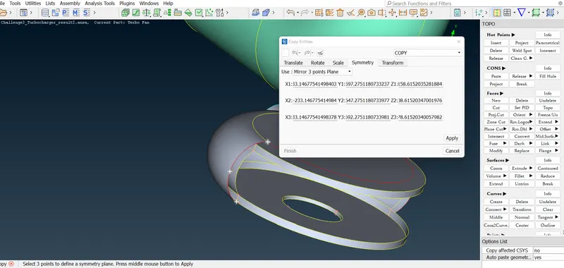
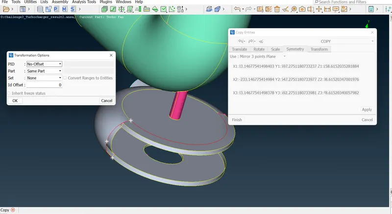
- After repairing the Compressor Casing, when viewed in the wireframe, it is observed that the turbine casing has missing surfaces. These surface, however, differs in character from the above surfaces as it is symmetric to the other half. So the Copy feature in Transform Menu is used. This tool enables the copying of the surface and mirroring across an Entity/COON.
- Before using the Transform tool, an extra Hot Point is added. This is to enable the mirroring of the surface.
- It is done by selecting Transform > Copy > Symmetry > Mirror three points plane.
- Further, the hole in the copied surface is filled by Fill Hole under the CONS menu.
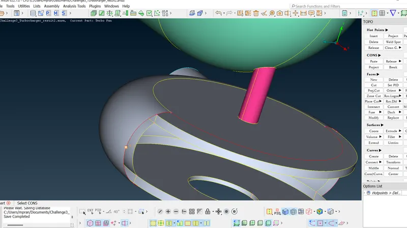
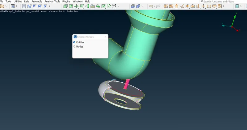
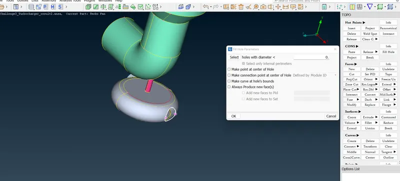
A final Topo (option under Faces menu) is done by selecting the entire surface to remove unnecessary red COONS. The blue COON from the Inlet is because of three surfaces combining at one place and hence, is unavoidable. Therefore, it is left as is.
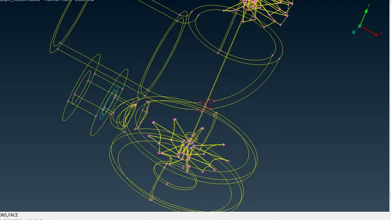
The Geometry is now cleaned. This can be viewed in wireframe mode as below.
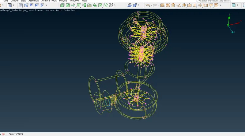
When closely observed, red COONs and blue COONs are observed mainly in Turbine Blades and in the vicinity of Compressor Blades.
3. Compressor Blades and Shaft
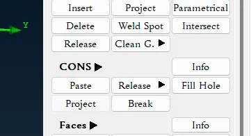
- The Compressor Blades and Shaft are noted to have intersecting surfaces. The surfaces are removed using two major tools. One is the Delete tool under the Faces menu and another is the Project tool under the CONS menu.
- The Project tool enables a projection of a curve on another shaft surface and cut the shaft accordingly. This removes the overlapping Shaft surface.
- The deletion of other overlapping surfaces is done manually by identifying the surfaces and deleting them one by one.
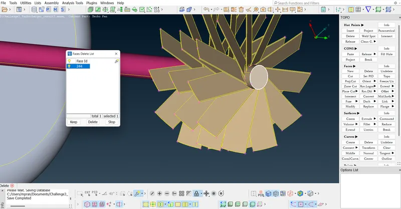
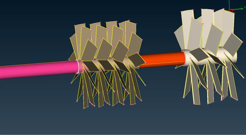
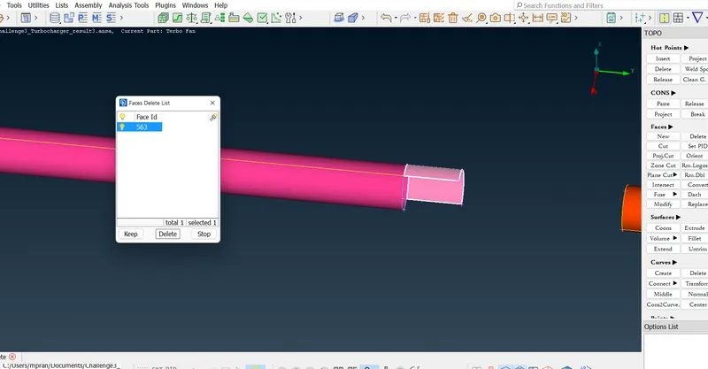
- After the deletion of the extraneous surfaces. Some necessary surfaces are also deleted in the process. These surfaces are then reconstructed to remove further errors.
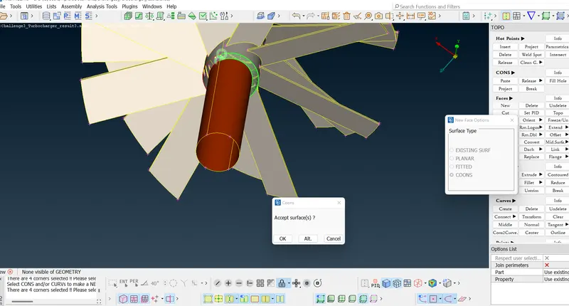
4. Turbine Impeller Blades and Shaft
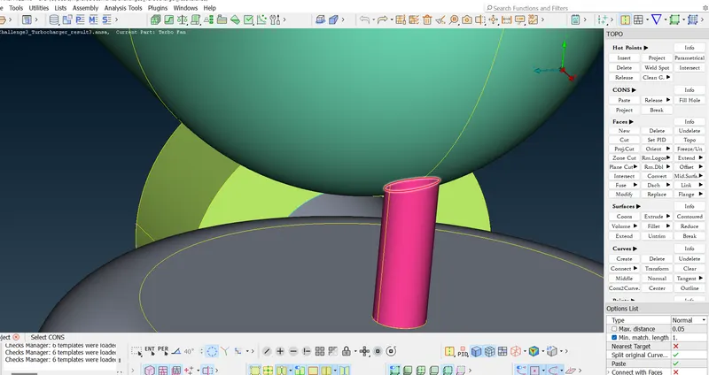
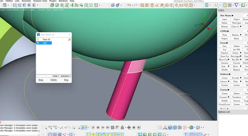
- The Shaft passing through the Compressor Casing to the Turbine Casing gives an intersection error. This is caused by the intersection in the shell surface of the Compressor Casing.
- This is removed by deleting the surfaces.
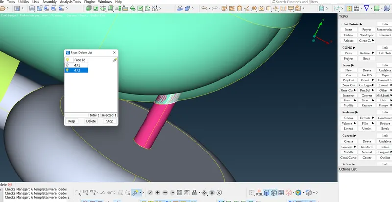
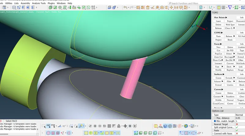
- However, after deletion of the surfaces, COONS in the shell surface become red showing geometry error. This is addressed with the help of the Project tool under the CONS menu.
- After projection, the extra surface is cut of the shell, thus removing the attachment of the shaft from the Compressor Casing.
Note that this is done, due to the requirement of Volume Meshing in the future.
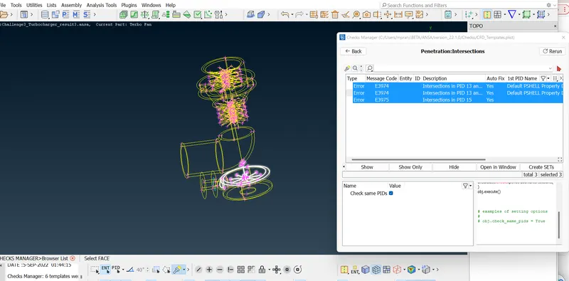
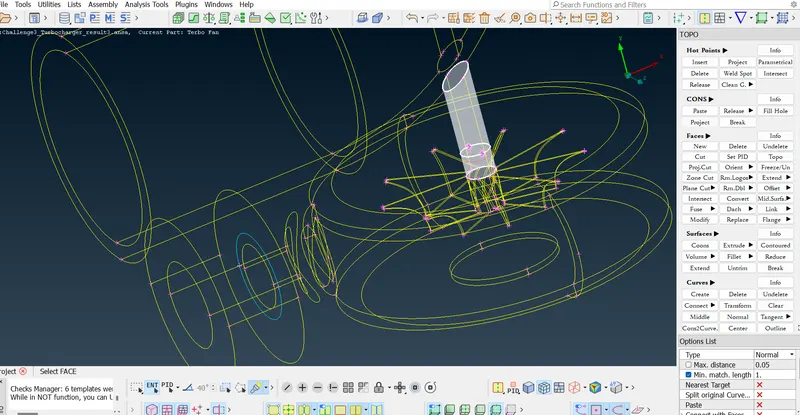
- Similarly, the intersection errors between the Turbine Casing and the Shaft are noted. These are addressed in a similar method.
- First, the extraneous surfaces are deleted, then the remaining surfaces are projected and the extra surfaces are later cut down after isolating the surfaces through the projection curve.
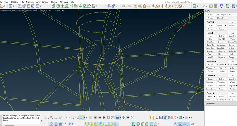
- After the removal of the above intersection errors, an overlapping surface error is detected at the face joining the Shaft and the Impeller Blades.
- This surface is deleted. However, this does not remove the bottom face. This is removed by first using the Cut tool and then the Delete tool.
- This in turn leaves red COONS. These red COONS are then removed by performing a Topo.
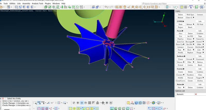
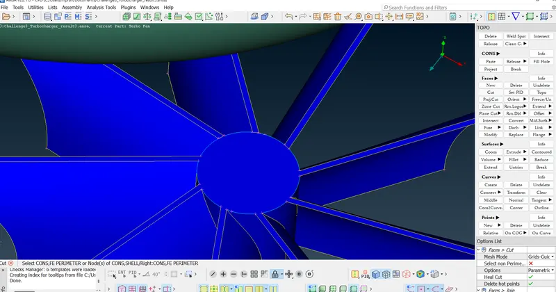
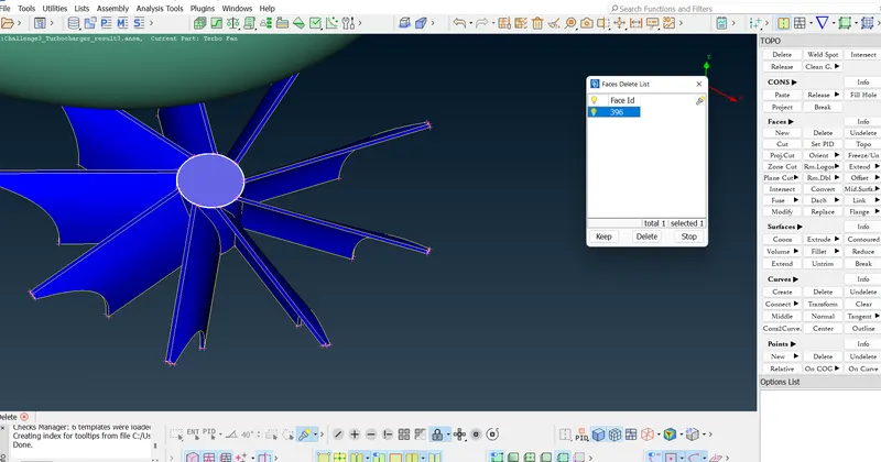
Before performing Topo.
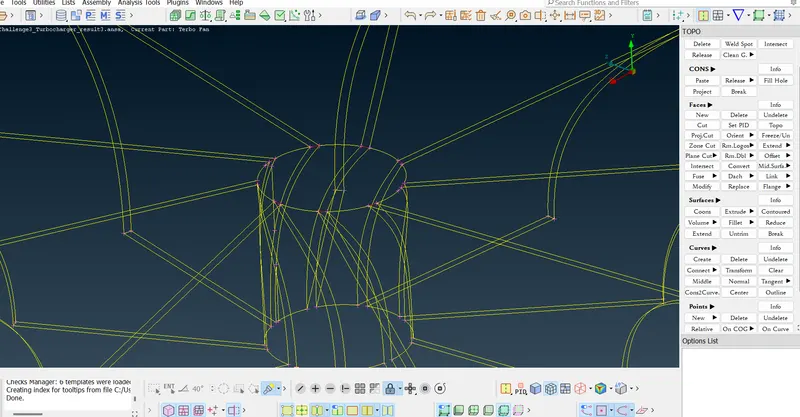
After performing Topo.
5. Miscellaneous Geometry Errors
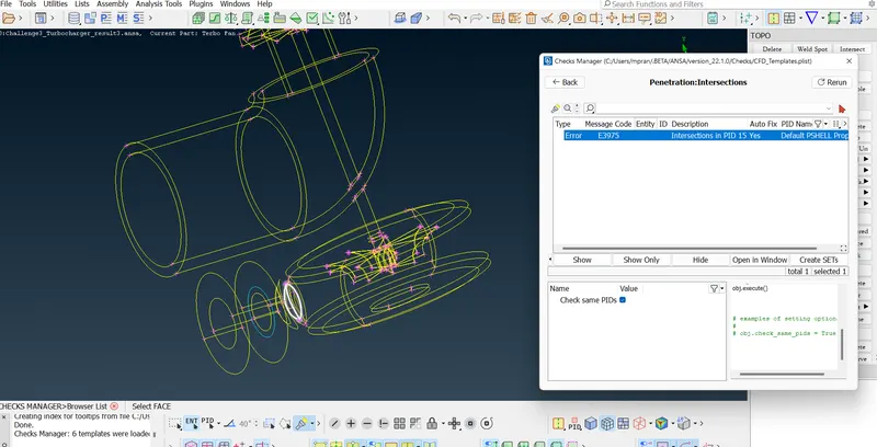
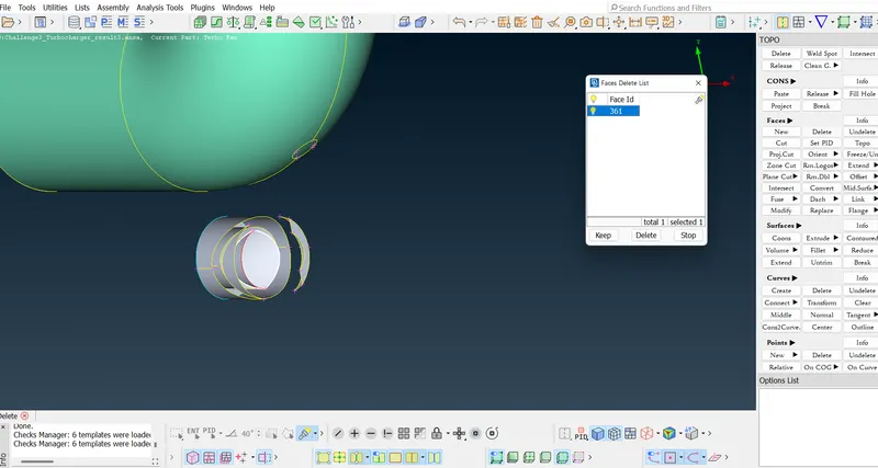
- These errors consist of any other extra surfaces that need to be deleted to remove intersection errors.
6. Closing of Surface
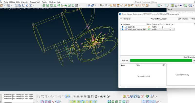
Since Volume Meshing will be done, the open surfaces are closed.
- Closed Surfaces are created by making a new face on the open surfaces by selecting Faces > New > COONS.
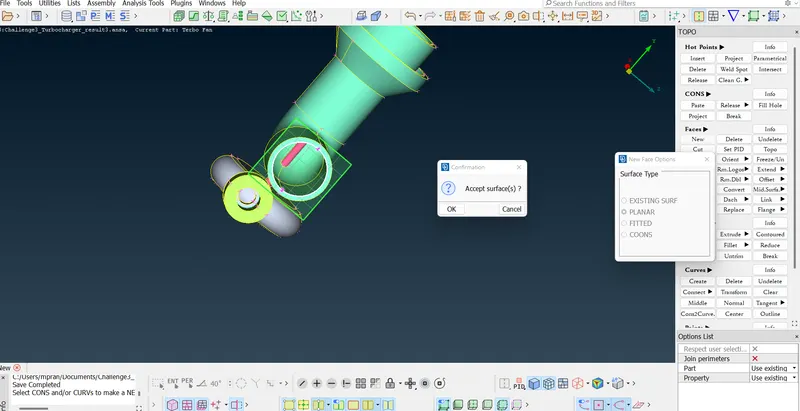
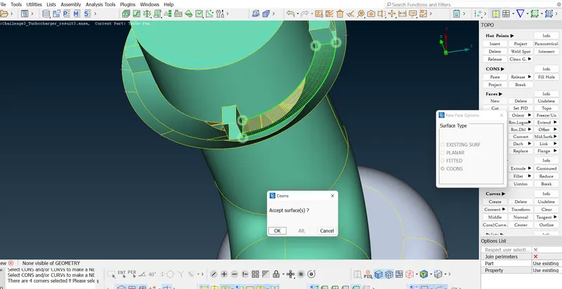
After finishing closing the surfaces, the parts are renamed as per the assigned names through PID menu in the top left bar.
II. Surface Meshing
For all the casings, the assigned target element length is 5mm.
- Turbo casing = 5 mm
- Compressor casing = 5 mm
- Inlet casing cover = 5 mm
- Firstly, the Left Menu bar is selected as Mesh (which was otherwise Topo during Geometry cleanup).
- Initially, the target length is defined by the Perimeter and Macro tool as 5mm under Perimeters > Length.
- After the definition of the target length, meshing is performed using SpotMesh under Mesh Generation.
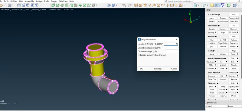
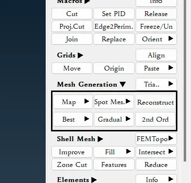
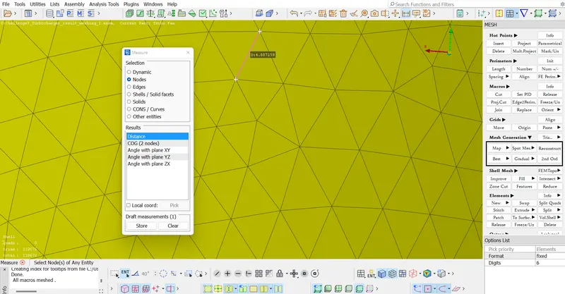
In the above image, we see the length of a randomly selected element. The element size can be greater than 5mm as well. However, the average element length will not exceed 5 mm with little deviation.
Similar steps are repeated for the Turbo Casing and Inlet Casing Cover.
Moving on to the Compressor Blades and Shaft, we have
- Blade stage-1 = 1 mm
- Blade stage-2 = 1 mm
- Shaft rotor = 1 mm
- The same steps are repeated while performing surface meshing of Compressor Blades and Shaft. This time the Perimeter and Macro length are set as 1mm.
- The same steps are again repeated while performing surface meshing of Impeller Blades. This time the Perimeter and Macro length are set as 2mm.
After performing the mesh generation, the PIDs are individually checked. It is observed that a few areas in some PIDs are unmeshed as it shows the unmeshed surfaces on the far left bottom along with the display of the total elements. The process is repeated for the unmeshed surfaces so as to complete the meshing.
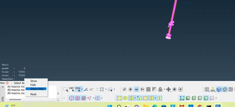
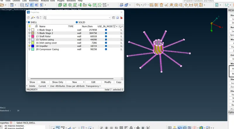
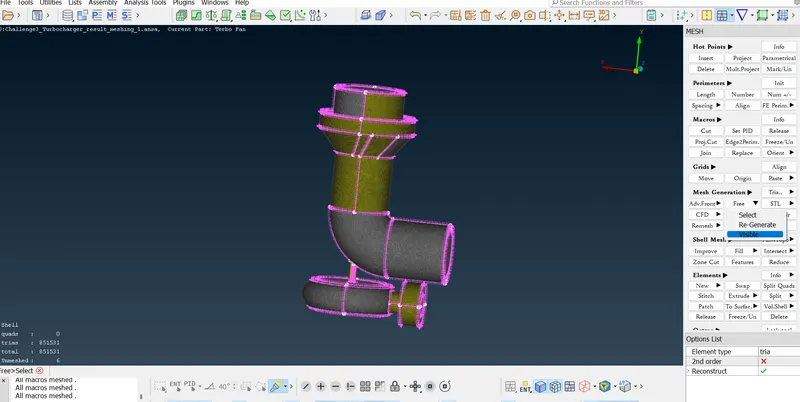
Once completed, when all the surfaces are made visible, it is observed that there are still a few unmeshed surfaces. This is because of the perimeter difference between 2 surfaces in contact. This issue is eliminated by using the Free tool in the Mesh Generation menu. This tool adjusts the perimeter length in the borders gradually adjusting the element size, moving away from the border.
III. Volume Meshing
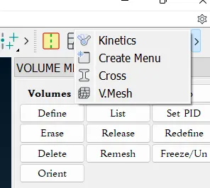
- After performing surface meshing, the volume meshing option is selected as shown below
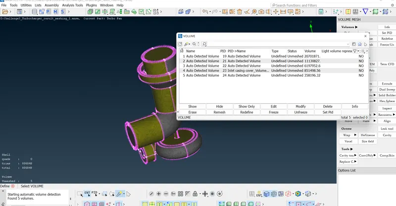
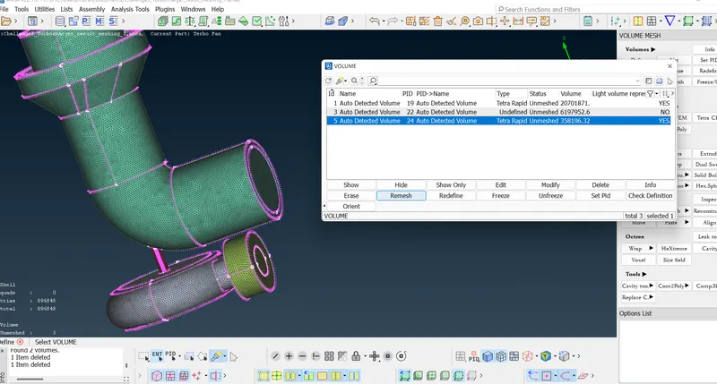
- Firstly, the Volumes to be meshed, are defined. This is done by selecting Volumes > Define.
- Clicking OK in the first pop-up window redirects to the second pop-up window which allows selecting the volumes necessary.
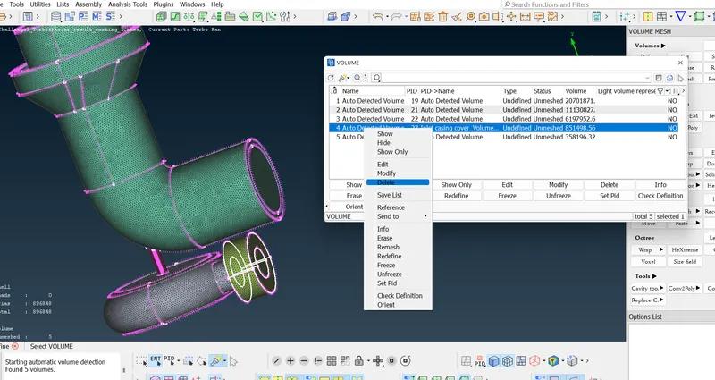
- Note that the inner volumes (wet volumes) are selected and not the volume generated by the outer shell. The outer volumes are deleted.
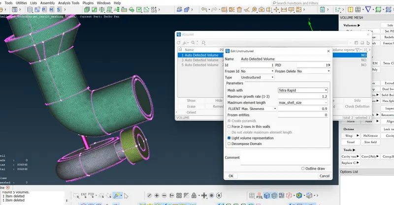
- The type of mesh required is stated in the required volumes. The Type is Unstructured and the Parameter is Tetra Rapid.
RESULT AND DISCUSSION
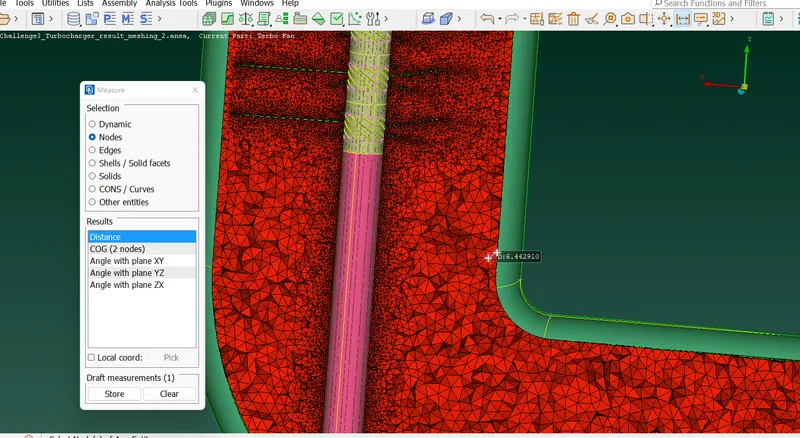
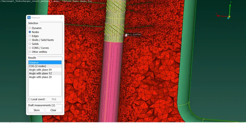
The volume meshing is done with a growth rate of 1.2. So it is found that the lengths of the tetrahedral meshes vary from 1mm at the boundary of the blades to 6mm at the boundary of the casing. This will help in studying the flow behavior near the blades due to the lower element size.
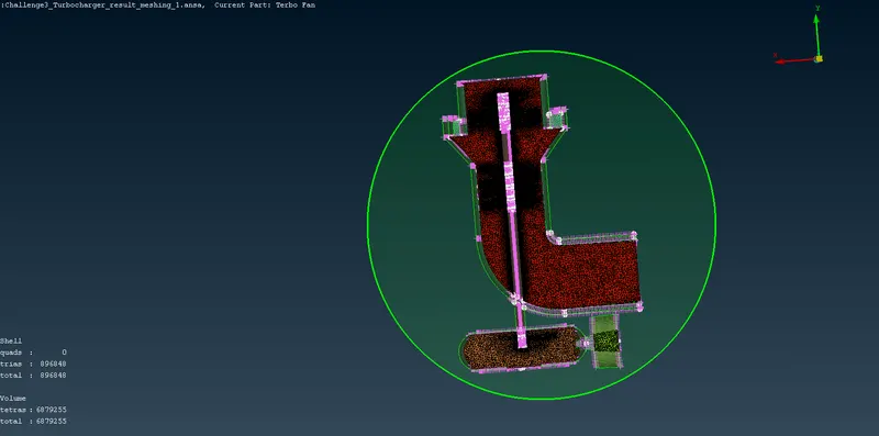
In the above image, the number of mesh elements is shown separately for both Surface Meshing and Volume Meshing.
We can conclude from the final meshing of all the given element sizes that the Meshing of any geometry should be done by taking into consideration the flow visualization needed, the computational feasibility, and the accuracy and consistency of the result. Only then, an efficient CFD simulation is possible.
Please find the models for geometry cleanup and final meshed geometry in the given drive link.
https://drive.google.com/drive/folders/1VjiO1qxiQwicCQPGuv-x4vaDD0m9hRAn?usp=sharing