Week 5 Challenge : Surface wrap on Automotive Assembly
AIM
- To remove the external geometrical errors and delete unwanted surfaces in all three geometries as directed in the session class.
- Merging of all three models (Engine, Transmission, and Gear Box) to Surface Wrap by treating it as one complete geometry.
THEORY
The Engine transfers the torque and power produced to the wheels of the car by Transmission and Gearbox. The Transmission box merely transfers the power to the gearbox, where the driver changes the gear based on the output power and torque required. In this particular case, a different technique for meshing is adopted as compared to the previous projects. The technique called Surface Wrapping is adopted. This technique is more commonly used for complex geometries where internal entities of the geometry do not matter due to external thermal/aerodynamic load analysis. It is also advantageous due to the water-tight mesh it forms taking into consideration only the outlining of the external geometry.
Following are the systemic steps adopted to Surface mesh the whole geometry.
1. Geometry Cleaning
In this project, the engine, transmission, and gearbox go through individual geometry cleaning. In the Engine primarily the unnecessary Rings and other surfaces are removed. In addition to that, in all the geometries, overlapping surfaces that are removable are deleted.
2. Merging
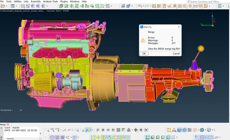
The three geometries after their respective geometry cleaning are merged one after the other. Merging of geometries is usually done by the MERGE option available under the File menu.
3. Geometry Cleaning after merging
Geometry cleaning is done for the miscellaneous part after the merging of the models. This is followed by the creation of surfaces to block all the holes. The creation of holes is an important step as it helps the Surface Wrap determine the outlining of the geometry properly and create a water-tight mesh.
4. Surface Wrapping
This is followed by the surface wrapping of the geometries. As mentioned earlier, surface wrapping takes only the outlining. Hence all the geometries are included in it. It is also important to note that the geometries of the PIDs need to be cleaned before wrapping as there are many redundant and unwanted PIDs. The target length of the wrap is 3mm.
PROCEDURE
On opening the ANSA launcher, the CFD layout is used along the performance mode 3 for efficient performance.
First, the cleaning takes place in the Engine geometry, then the Transmission, and finally the Gearbox.
I.Geometry Cleaning
1. Engine
- The Engine geometry as seen initially has numerous unwanted surfaces. These surfaces cause not only distortion but also a huge number of geometric errors. These errors are removed systemically with help of the Univerasal Delete option in the Menu bar.
- The important engine geometry entities are recognized and hidden first using the NOT option. Then the unwanted surfaces are deleted steadily ensuring any important geometry part does not get deleted.
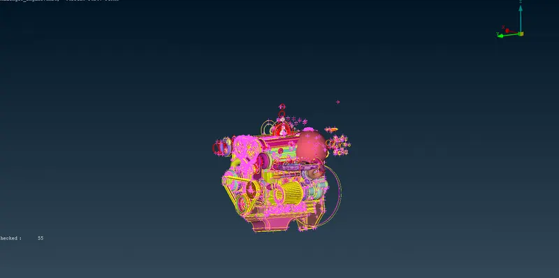
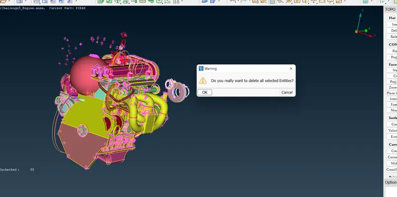
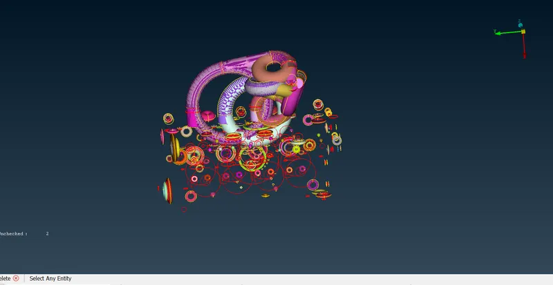
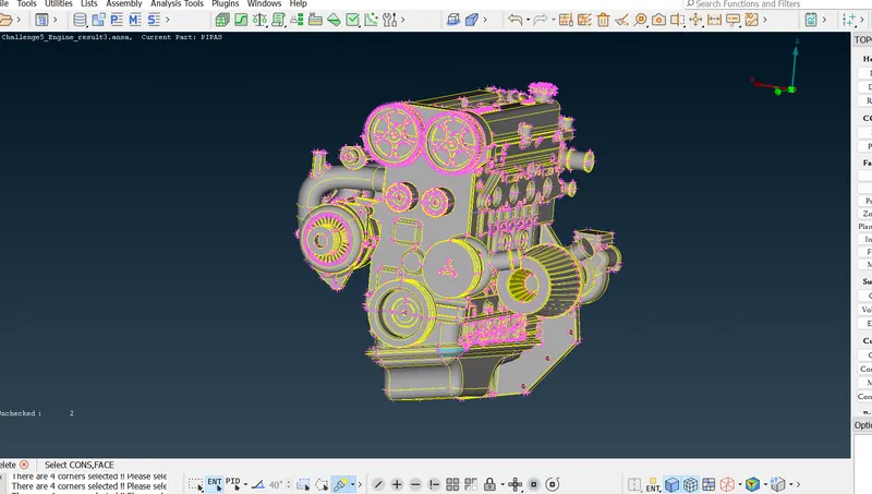
- The image below shows the unwanted parts after hiding the major important parts of the engine.
- After the deletion of the unwanted error-causing entities, the engine is unhidden and errors in the external geometries are addressed.
Please note that all the errors are not hundred percent removed as the main agenda is to make a uniform surface outlining.
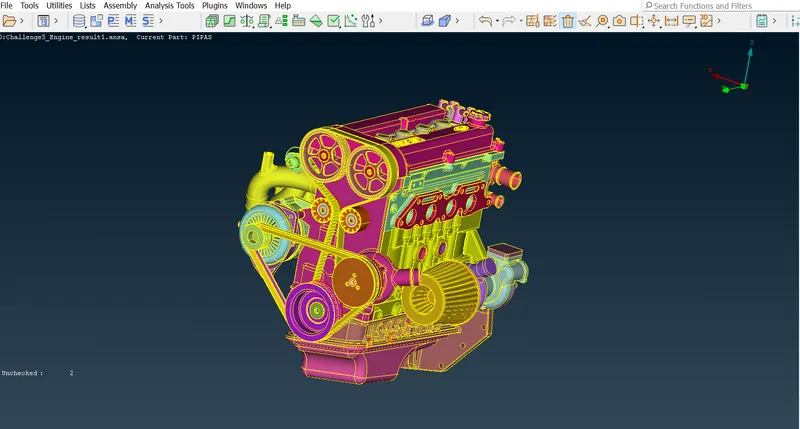
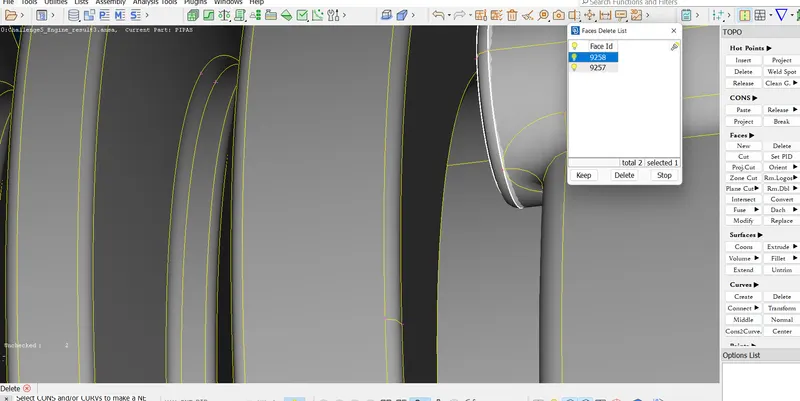
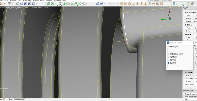
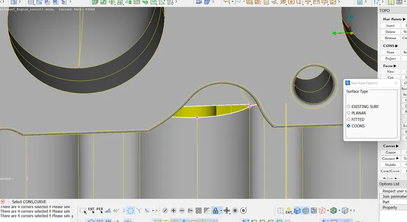
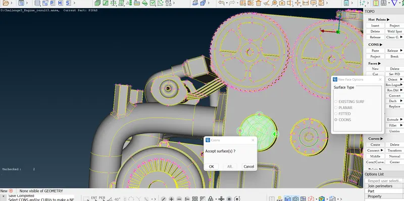
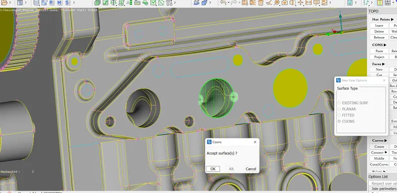
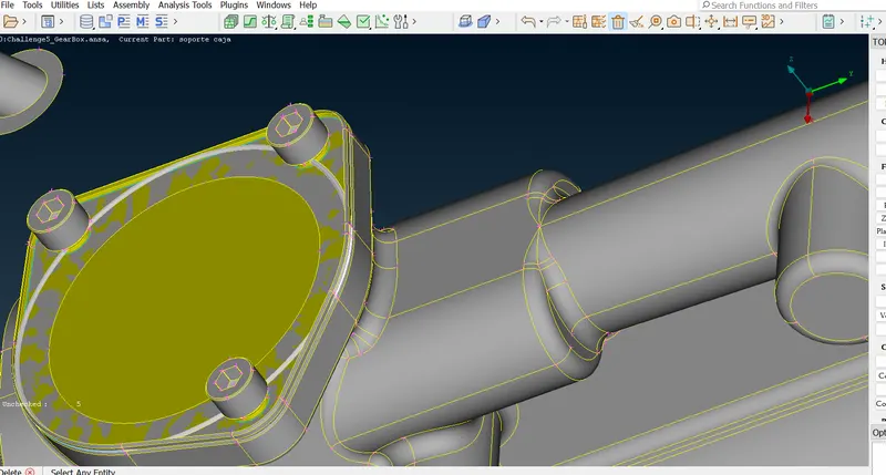
- One example of the deletion of overlapping surfaces and the creation of external surfaces is shown below.
2. Transmission
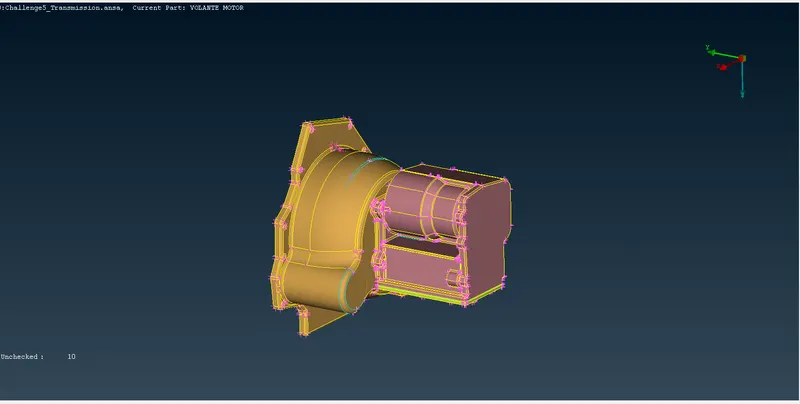
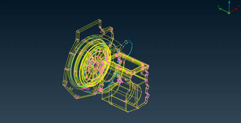
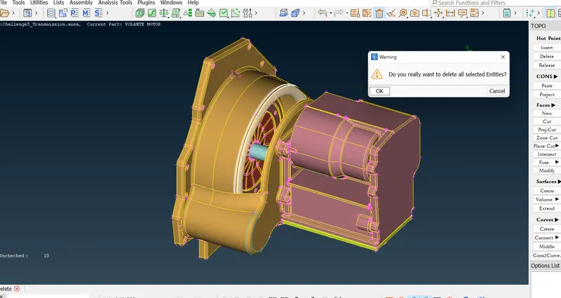
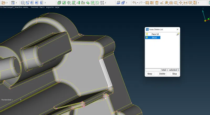
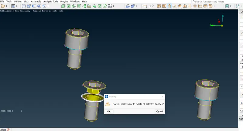
- In this case of the Transmission box, there are significantly fewer error-prone overlapping surfaces and geometries. This can be addressed using the Face Delete and Face New tools in the Topo Menu.
3. Gearbox
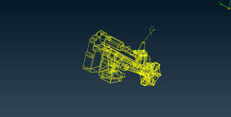
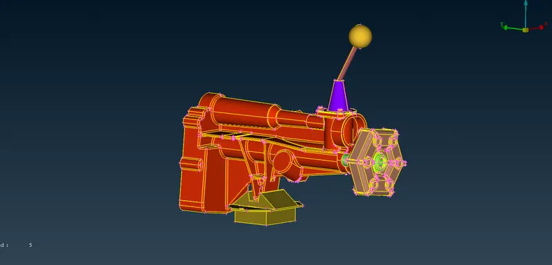
- Similarly, the gearbox is geometrically cleaned.
II. Merging
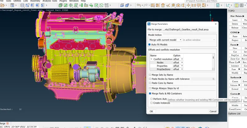
- The merging of geometries is carried out one after the other using the MERGE option under File Menu.
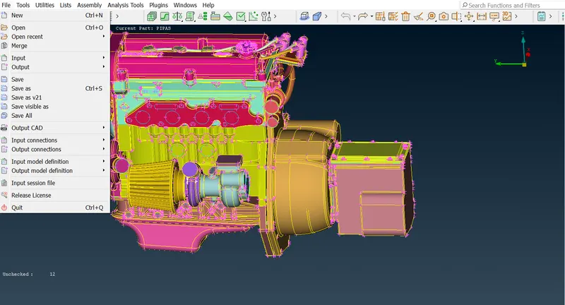
- On selection of the MERGE option, the geometry selection option appears that defines the selection of what geometry to merge.
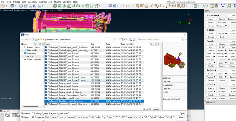
- The Auto Fit Models option is selected in this case. Also, it should be kept in mind that the Merge with current model is selected. Note that there should be no warnings.
III. Surface Wrapping
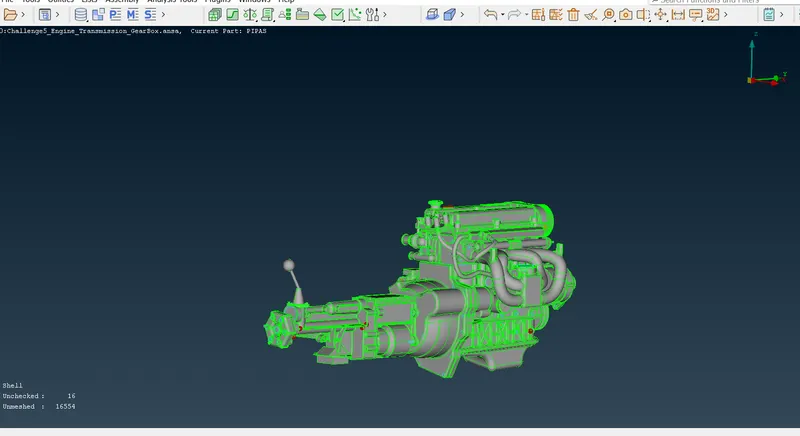
The surface wrapping is carried out with the required target length.
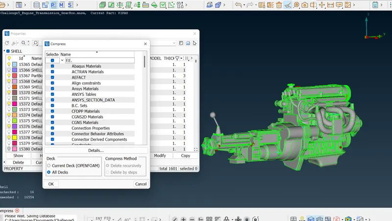
- However, before the surface wrapping, the PIDs are cleaned using the Compress option in the Menu bar.
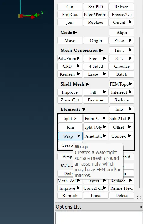
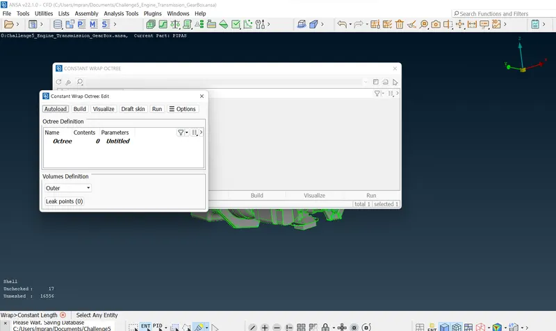
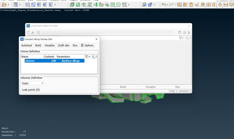
- Upon selection of the geometry, the Target Length for Wrapping is set. The 25 is changed to 3.
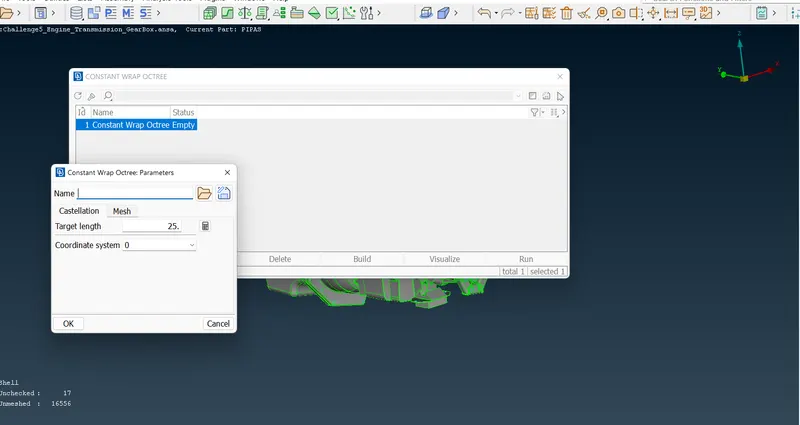
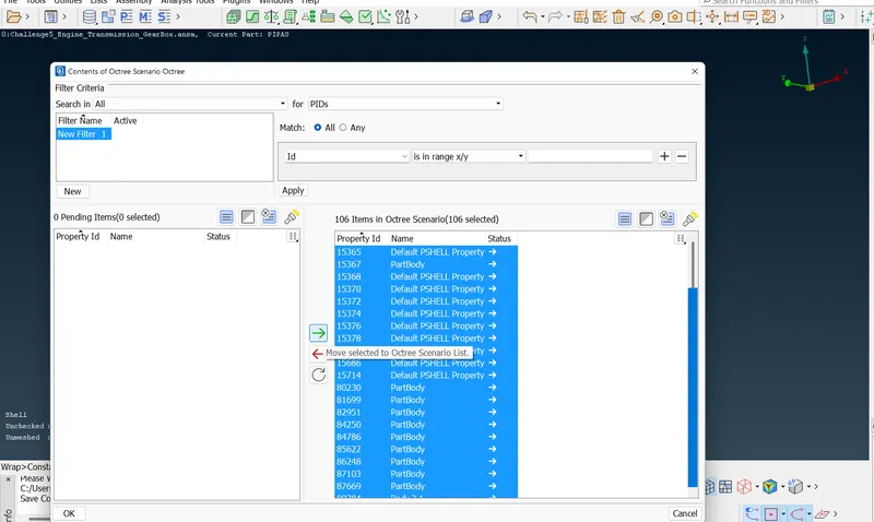
- Further, the PIDs for the wrap are selected. Here we select all the PIDs. Please note that this window appears on double-clicking the Octree Map. Also, it can be renamed.
- It can be seen that 106 elements are selected as opposed to 1500+ elements initially. This number reduces due to compression. The name is renamed as "Surface Wrap".
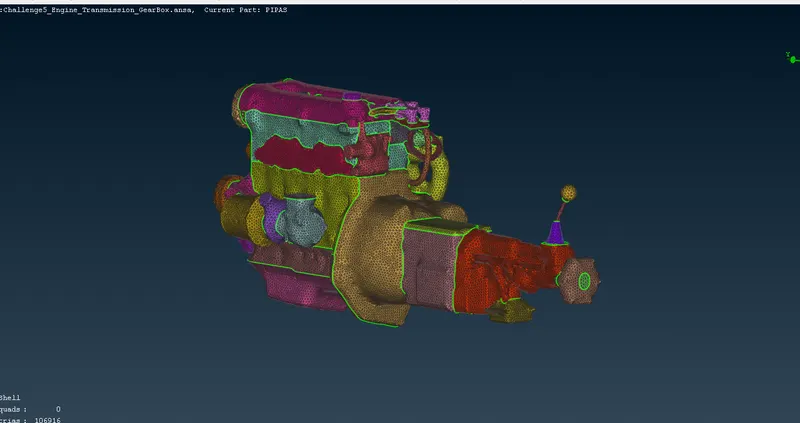
- After all the above procedures, the Run option is selected and the Surface wrapping is done.
RESULT AND DISCUSSION
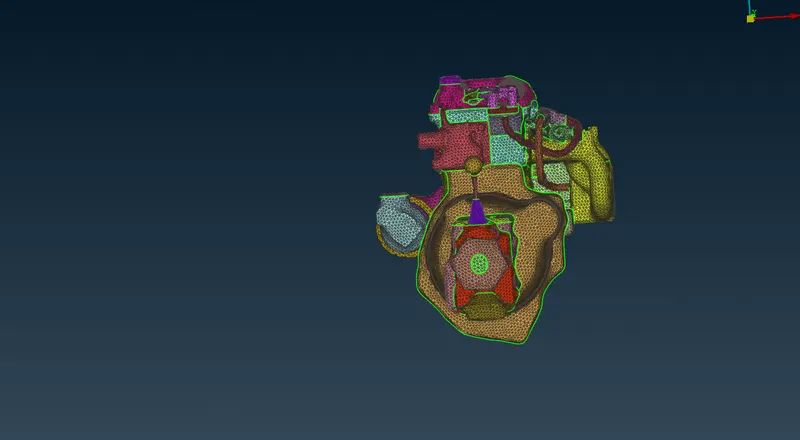
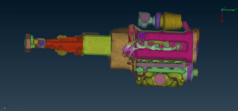
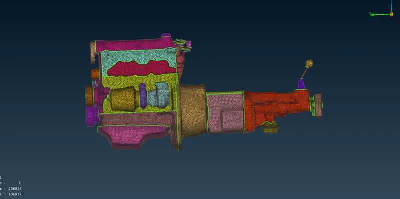
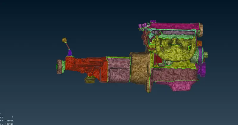
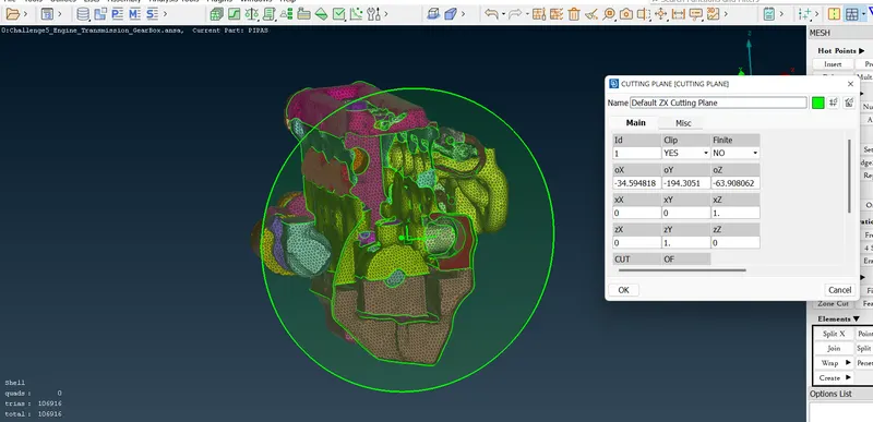
It can be noted that on Surface Wrapping, the geometrical outline is taken into consideration, and on slicing it vertically, it is found that the internal engine entities are neglected. This is the main function of Surface Wrap. The outlining geometry is highlighted significantly creating a water-tight mesh that helps in the thermal and fluid flow analysis.
Below is the google drive link to the solution. Please let me know in case of an error to access the drive link.
https://drive.google.com/file/d/1wO3oTpJt3xr7LyiXKKJBzIirE6nnS8pT/view?usp=sharing