Project 1 : CFD Meshing for Tesla Cyber Truck
Project 1 : CFD Meshing for Tesla Cyber Truck
AIM
- To remove the geometrical errors and perform a Topology cleanup in the Tesla Car geometry.
- To create and assign PIDs and perform Surface Mesh as per assigned target lengths for PIDs and element Quality Criteria
- Construct a surface for Wind Tunnel and surface mesh the wind tunnel.
Note - There have to be Zero Off elements and only 2D Tria elements.
THEORY
The Tesla car in the given problem has been meshed for Aerodynamic flow analysis. For the Aerodynamic flow, a Control Volume is made in the form of a Wind Tunnel for simulating the flow of air. However, due to expensive computation, volume meshing of the Wind Tunnel is not done and a surface mesh is adopted as a mere representation of the former. Following are the systemic steps adopted to Surface mesh the whole geometry,
1. Geometry and Topo Cleaning
The geometry and topo cleaning includes all kinds of removal of geometric and intersection errors in various parts of the car chassis. In addition to that, it also includes the geometry cleaning of tyres. The geometric errors are removed with simultaneous creation and deletion of surfaces.
2. Surface Meshing of Car
The car's surface is being meshed for Aerodynamic testing. Each part of the car is meshed with a defined Target length. This is done in accordance with the values given in the problem. To perform the surface meshing at different parts of the car, the parts to be meshed are frozen to avoid the occurrence of unmeshed surfaces due to a common perimeter with different target lengths.
3. Creation and Meshing of Wind Tunnel
After the surface meshing of the car, a cuboidal surface is made to simulate the wind tunnel. Further, the wind tunnel is surface meshed.
Mesh parameters
Setting mesh parameters include setting up mesh element length and also mesh quality criteria is crucial for a high-quality mesh. Here, the design will consist of different mesh sizes for different parts of the geometry and the required quality criteria. In an industry scenario, it becomes extremely crucial to determine the mesh size based on the simulation to be carried out.
The mesh parameters assigned as per PIDs are
- Body - 3 mm
- Lights - 4 mm
- Rims and Tyres - 2 mm
- Window - 2 mm
PROCEDURE
On opening the ANSA launcher, the CFD layout is used along the performance mode 3 for efficient performance.
I. Geometry and Topo Cleanup of the Car
- On importing the intersection surfaces and red cons can be evidently seen in the below views.
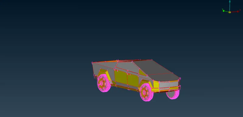
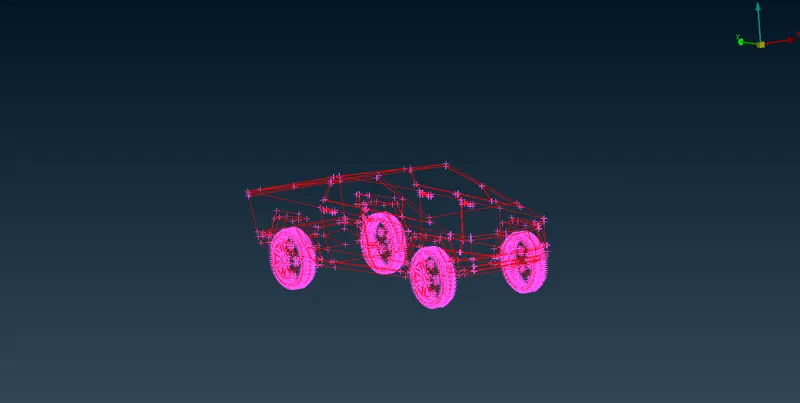
- A topo is done initially to clean up the geometry.
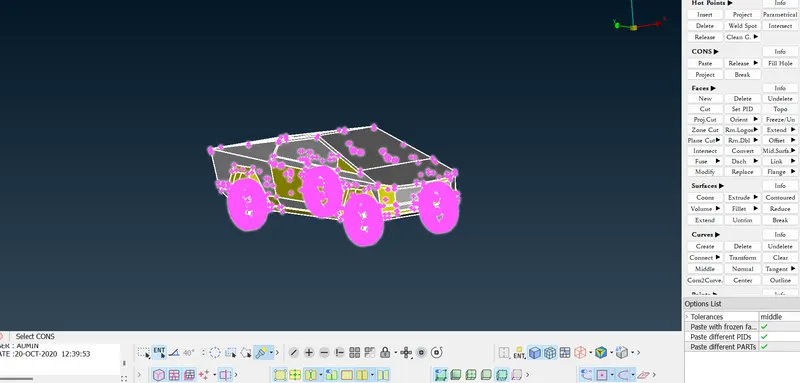
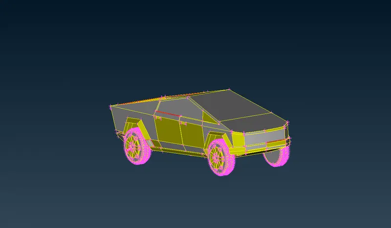
- The missing surfaces are added to the gaps respectively.
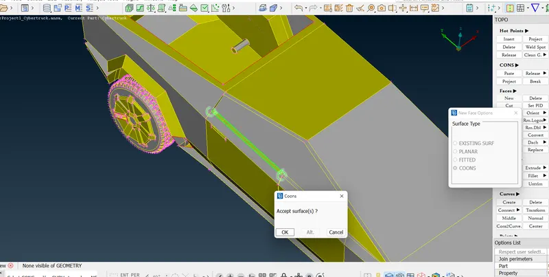
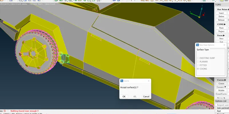
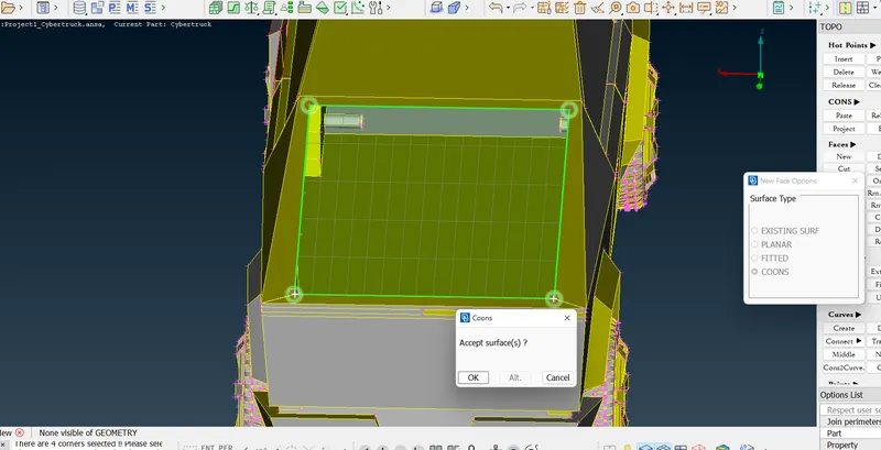
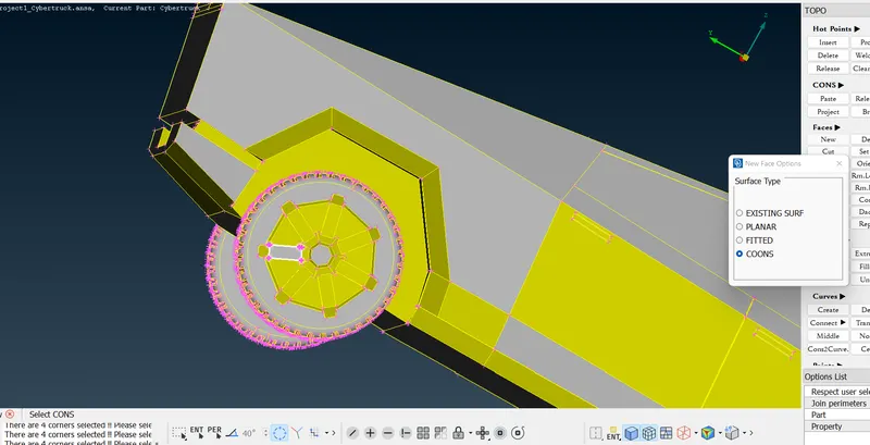
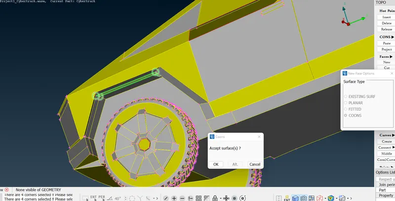
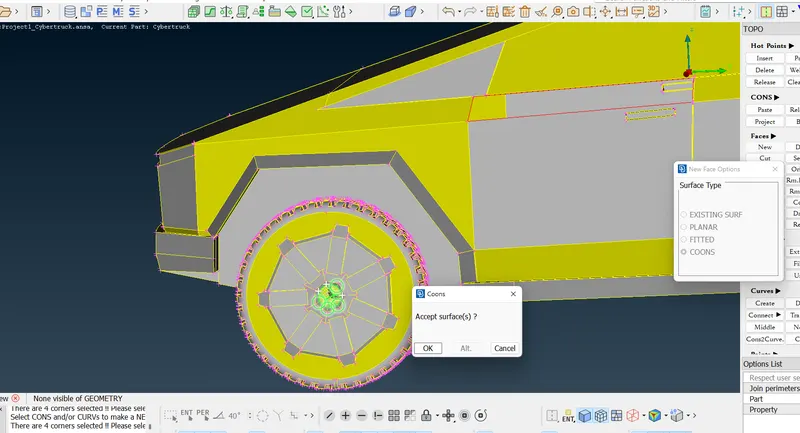
- After the addition of the surfaces, a geometric check shows the existing warnings in the geometry and intersection errors.
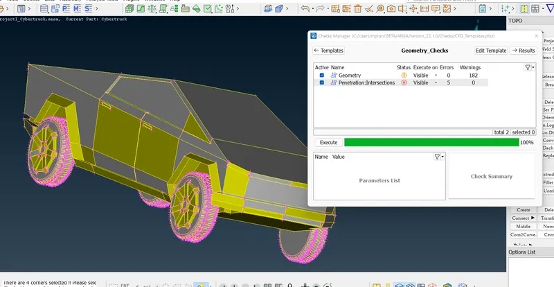
- The intersection errors are addressed initially.
- Wherever required surfaces are reconstructed without damaging the integrity of the geometry.
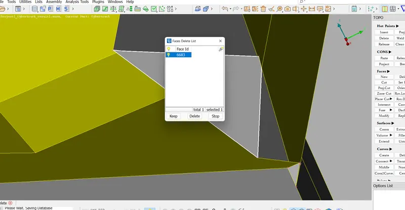
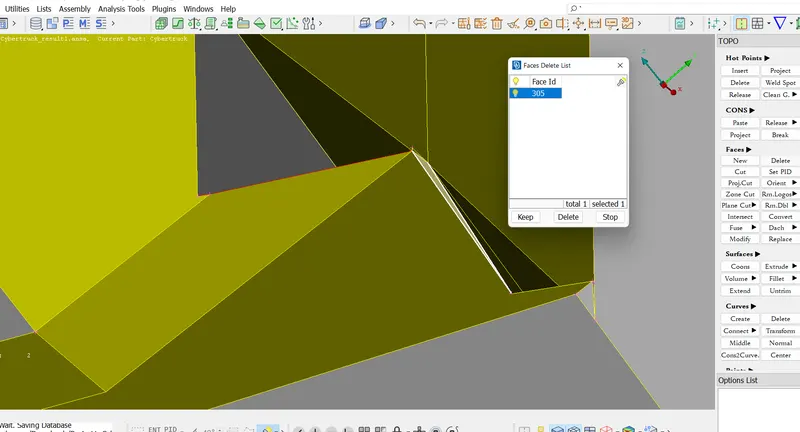
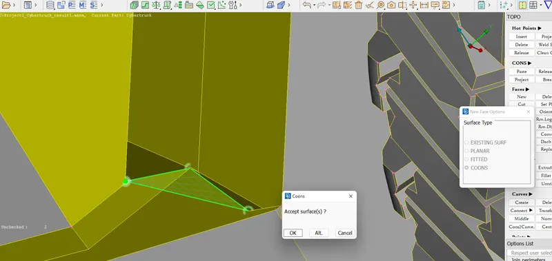
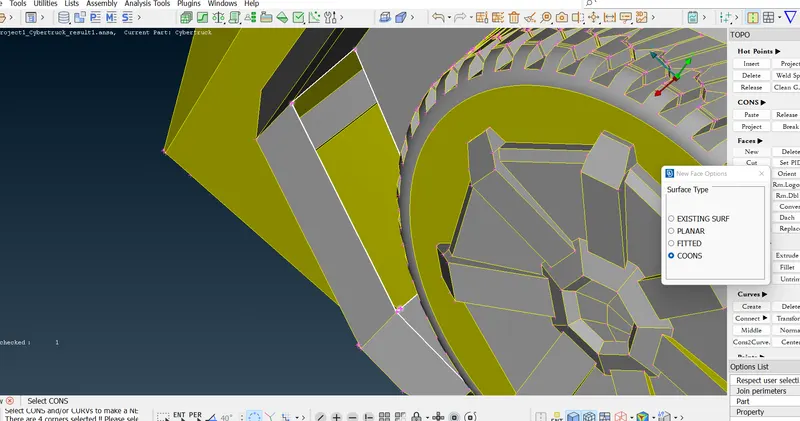
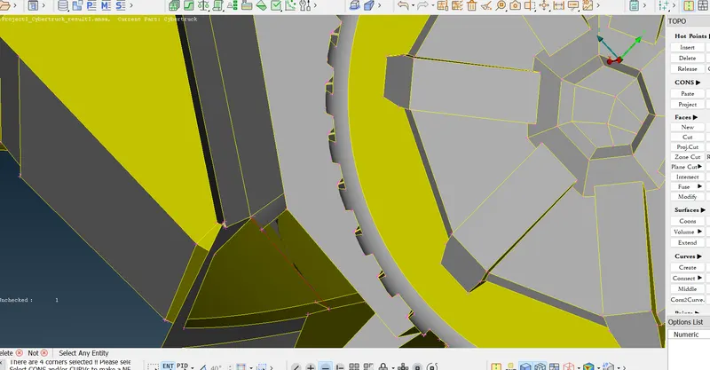
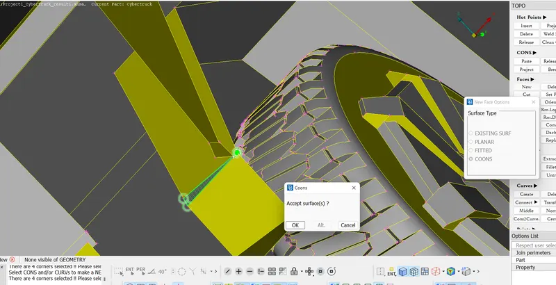
- As shown in the image the above steps are repeated for other parts of the geometry from the bonnet to the axle of the wheels.
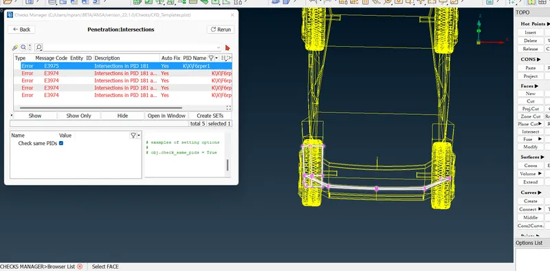
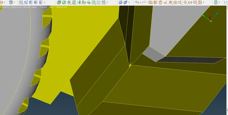
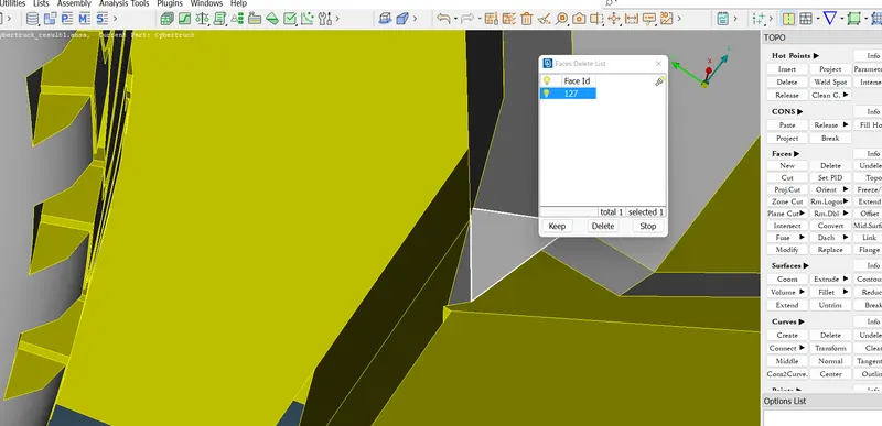
- After the removal of intersection error from the front headlight-rim surface, the intersection errors in the axles are reported.
- The axles have overlapping surfaces which are deleted to remove the errors.
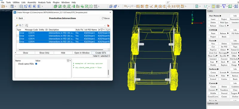
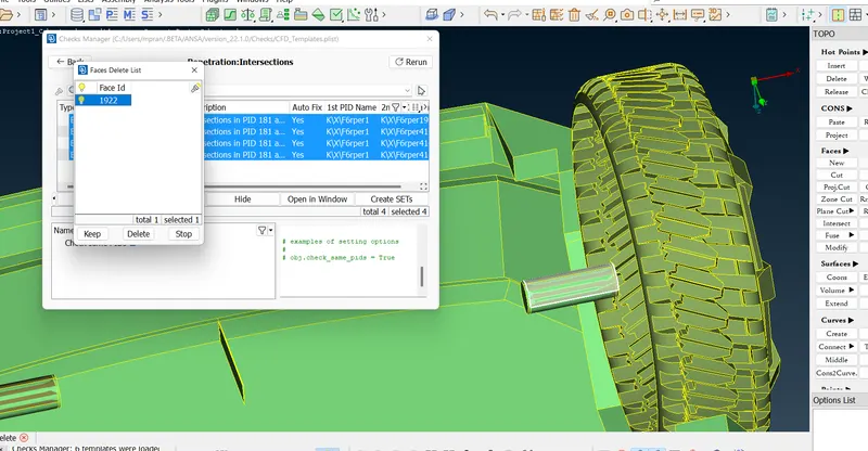
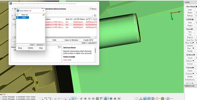
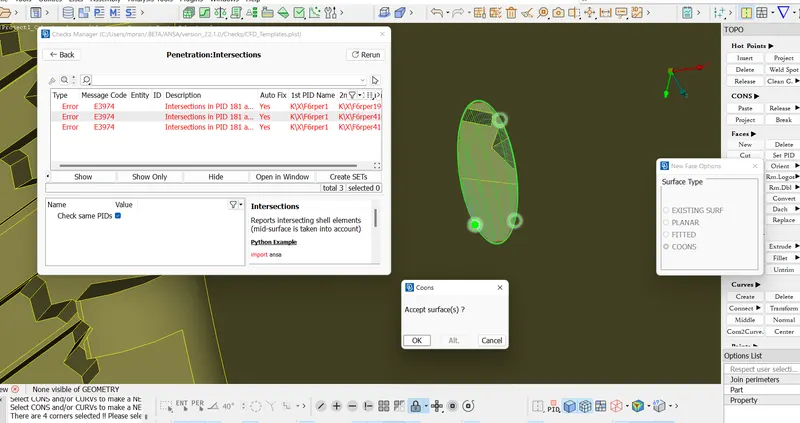
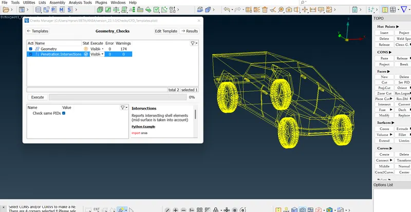
All intersection errors are removed.
Before the surface meshing, the geometry is divided in half like that of the BMW.
The reason for the deletion is primarily because of the huge geometry and computation time it takes to mesh the whole car. Therefore, the first half of the car is meshed as per the target lengths, then the second is duplicated with the help of the Transform tool.
II. Surface Meshing of Car
In the surface meshing of the car, the primary objectives are to adhere to the target lengths, adhere to the quality criteria, and not deviate much from the same, and on these lines make a meshed structure using trias without any Off elements. On surface meshing the extreme lengths in Quality Criteria are always selected as higher extremes than the Mesh Parameter's lengths. This is in order to have an error-free mesh as extreme target lengths do not necessarily mean that element size in a few areas won't cross it, especially in the common perimeter zones.
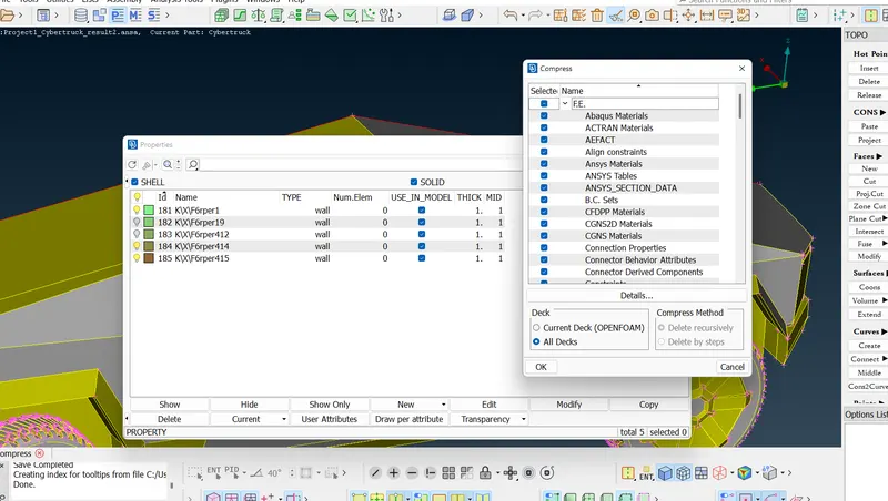
Note that every Entity below is defined as a PID before being meshed.
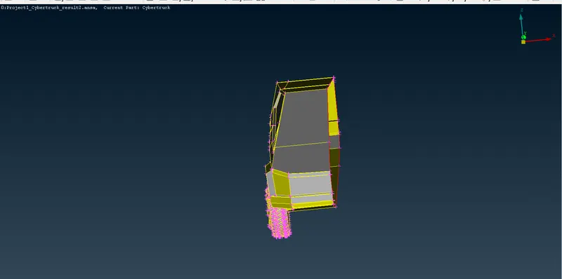
1.Window
In this case there are some important points to be noted.
- The mesh target Length range is set by Mesh Parameters in the menu bar. Min. Length = 1.5mm and Max. Length = 2.5mm
- Then the Mesh Quality Criteria is set in the menu bar. The overall quality criteria here used is Min. Length = 0.5mm, Max. Length = 8mm, and Skewness = 0.5.
Note - The quality criteria are set for the overall meshing. Therefore all the target lengths have been kept into consideration while designing the quality of the mesh.
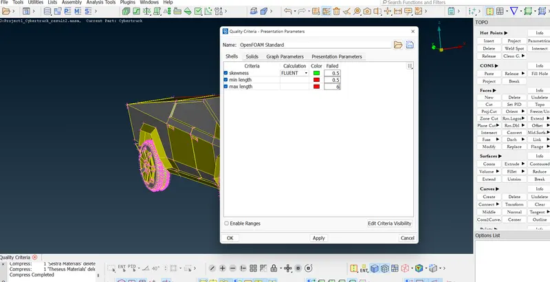
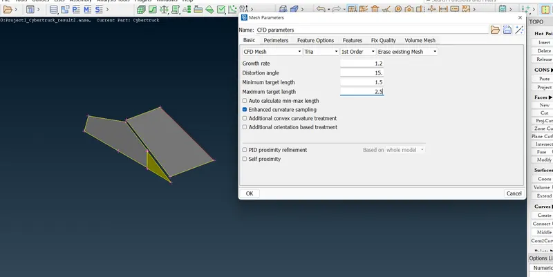
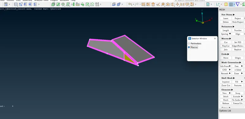
- After completing the meshing, Off Elements appear in the window.
- These Off Elements are addressed by Reconstructing and Reshaping the elements.
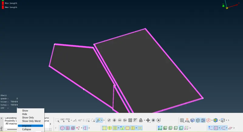
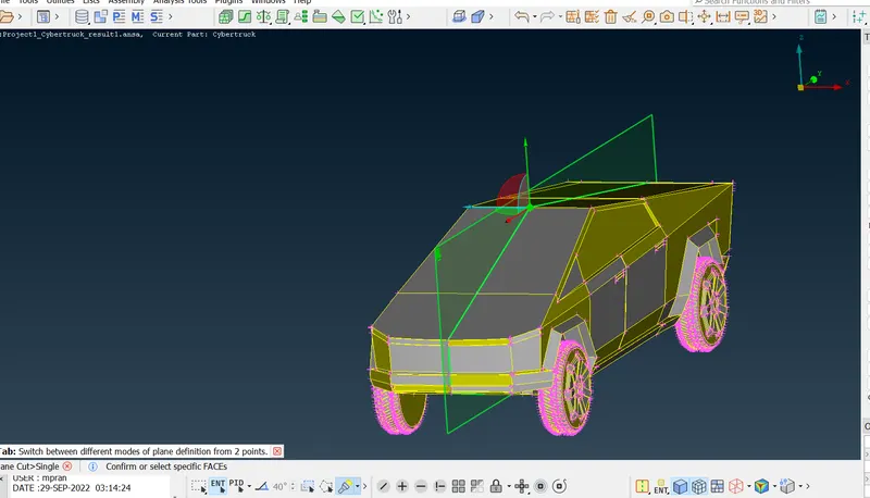
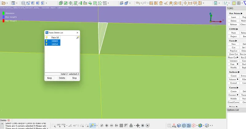
- After addressing all the elements, it is noted that there are still 2 Off Elements. These elements are skewed due to their geometry. As can be seen below.
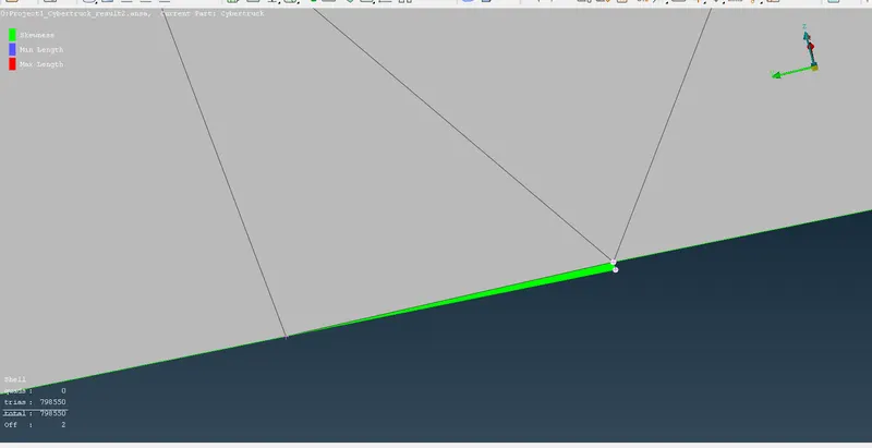
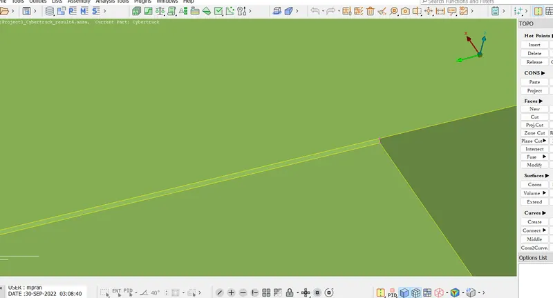
- This is eliminated by making a cut in the geometry and shifting this surface to the chassis(body) of the car.
- Below is the image depicting the cut made to separate the surfaces. The upper part of the cut belongs to the window section. whereas the lower part belongs to the chassis thus separating the surfaces, and hence eliminating the skewness error in the geometry.
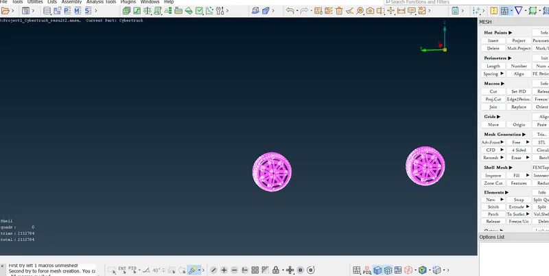
2.Tyres
- The mesh target Length range is set by Mesh Parameters in the menu bar. Min. Length = 1.5mm and Max. Length = 2.5mm
3.Lights
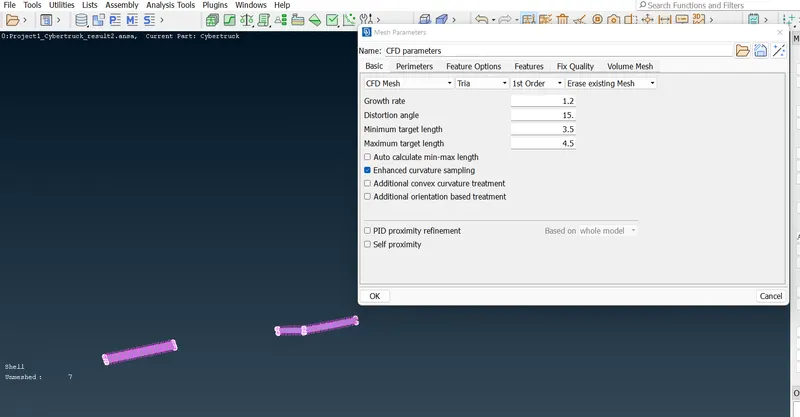
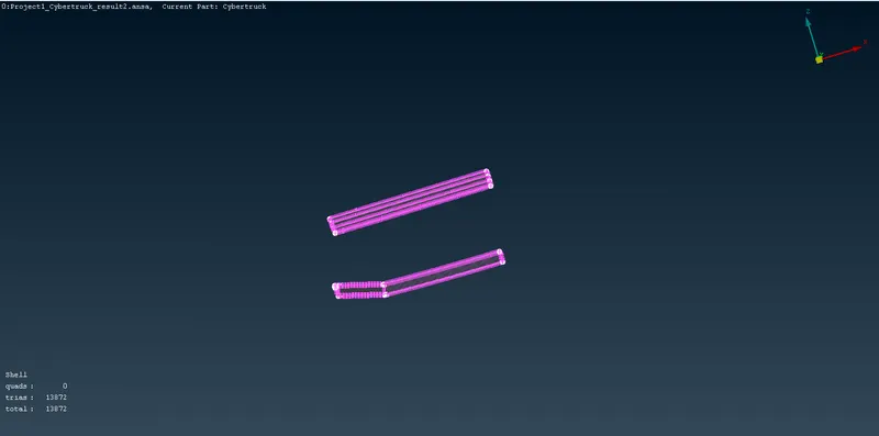
- The mesh target Length range is set by Mesh Parameters in the menu bar. Min. Length = 3.5mm and Max. Length = 4.5mm
4. Body
Before, meshing the body, the mesh in the other geometries are frozen. This is to avoid any elimination of mesh in the adjoining surfaces due to common perimeters with different target lengths.
- The mesh target Length range is set by Mesh Parameters in the menu bar. Min. Length = 2.5mm and Max. Length = 3.5mm
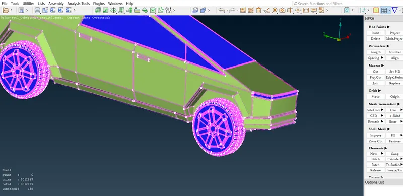
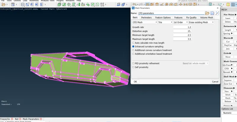
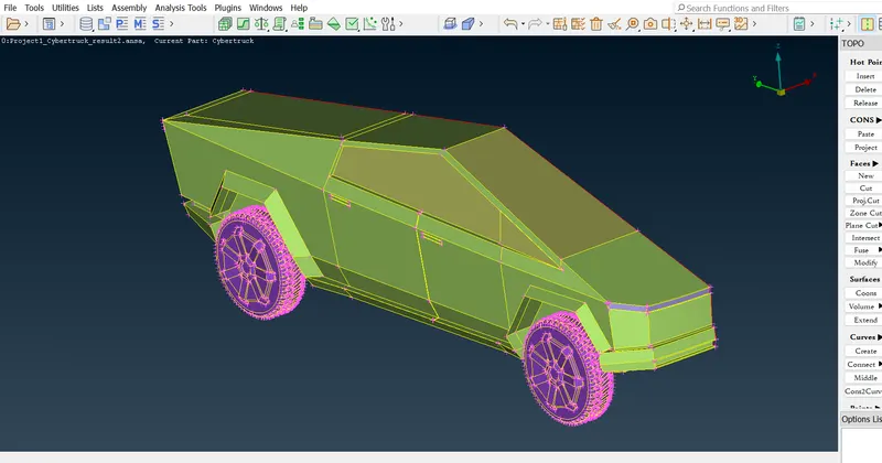
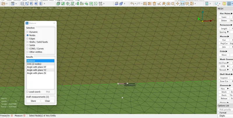
- The comparison between the surfaces of the Window and Body can be seen below. This shows the common perimeter shared by the PIDs and the common perimeter hence adopted is not in violation of any of the geometries.
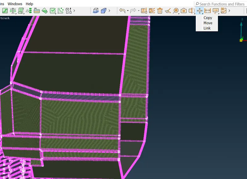
Further, the geometry is duplicated for the other half of the car with the help of the Transform tool.
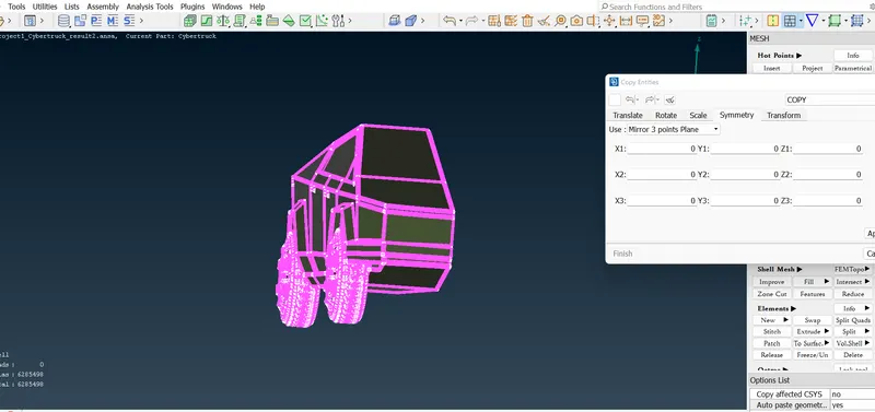
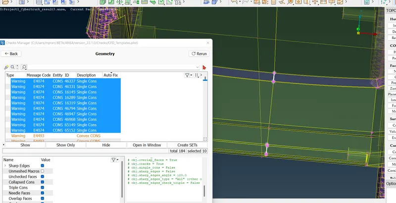
- After duplicating the geometry, some errors near the light and front bonnet are detected. These Red CONS are addressed by remaking the surfaces.
- Remaking the surface, instead of simple addition avoids the skewness errors that could occur on the surface.
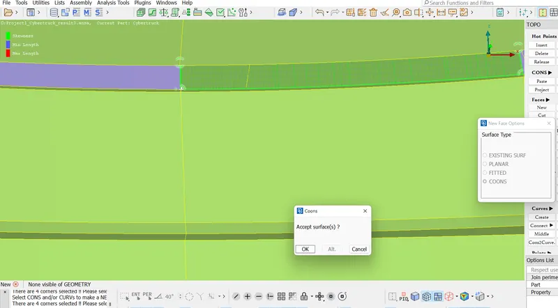
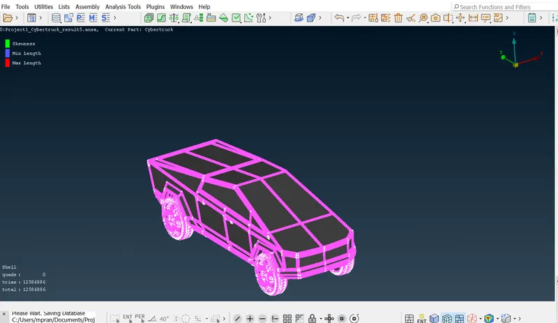
- The final mesh of the surface looks like the following.
III. Creation and Meshing of Wind Tunnel
The creation of the Wind Tunnel is carried out through the dependency on the length of the car.
- Distance from the bottom of the car = 800mm
- Distance from the front of the car = 4x mm
- Distance from the back of the car = 6x mm
- Distance from the top of the car = 3x mm
- Distance from the sides of the car = x mm
where x= length of the car = 5900 mm.
The geometry is created by adding Relative Points in the respective distances. These points are then joined by the Create > Curves. The surfaces are created using the New > Faces > COONS. Offset surfaces are created in accordance with the length directed through Offset > Faces.
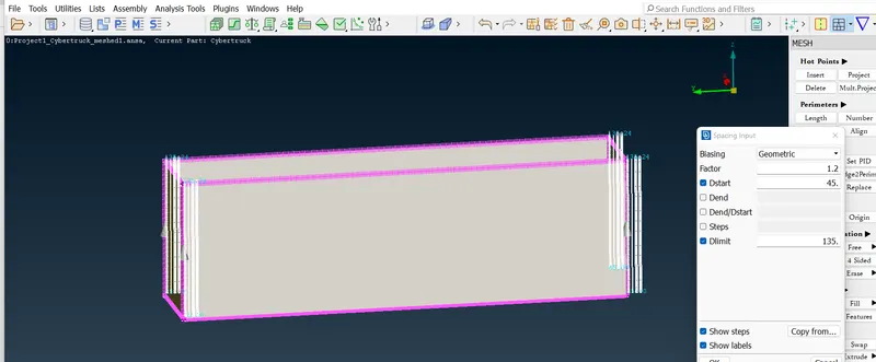
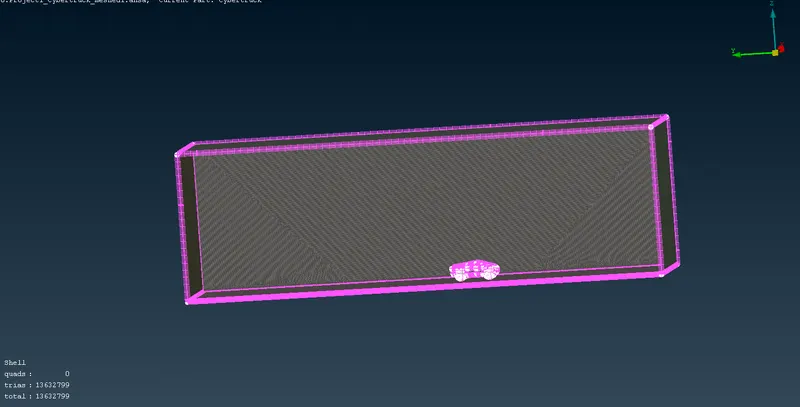
After the creation of the geometry, the meshing is performed with different target lengths and biasing. Please note that the Target Lengths in these cases have been increased slightly due to the computational inability to mesh smaller size elements across large surfaces.
Bottom Surface = 35-55 mm
Top Surface = 105-135 mm
Side Surfaces = 45 - 135 mm Growth Rate = 1.2 with biasing from the bottom to the top.
- At first, the bottom surface is created, followed by the top surface with the help of the Offset tool, and finally, the side surfaces are joined together.
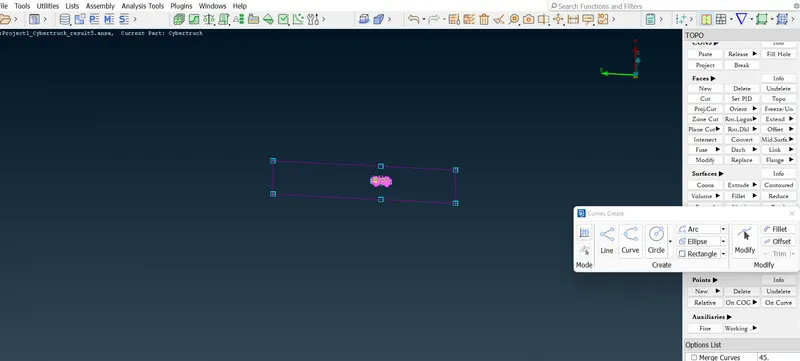
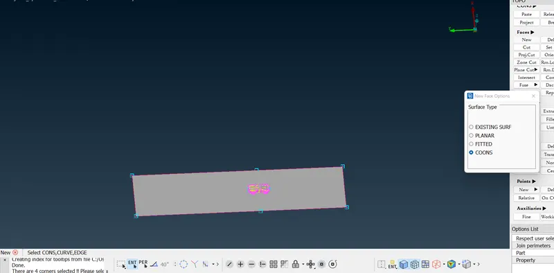
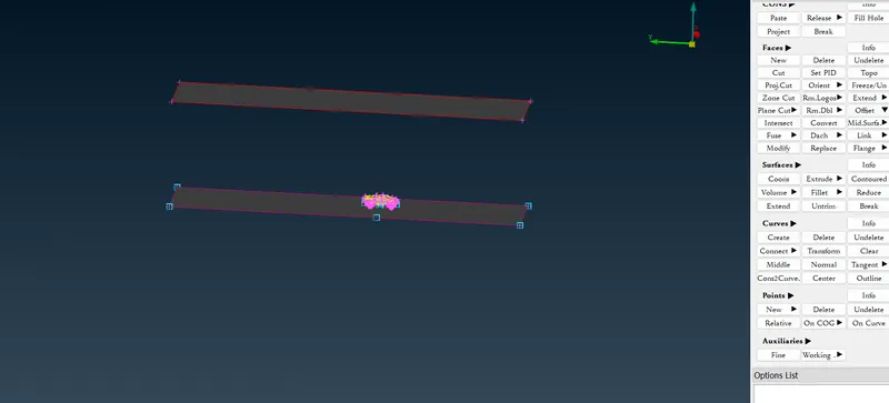
- Every surface is assigned a PID and then meshed according to the size mentioned above.

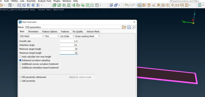
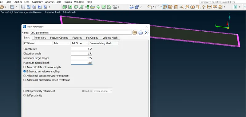
RESULT AND DISCUSSION
The result shows the importance and best practices of surface meshing that is necessary for external fluid flow simulation. A few of the important takeaways are
- Elimination of unrequired volumes for surface meshing for external flow simulation
- Creation of Plane Cuts, Projections, Curve creation, and other tool features necessary for advanced geometric cleaning.
- Importance of Meshing Parameters and Quality criteria
- Importance of Growth Rate and BIasing to create a biased mesh.
Below is the google drive link to the solution. Please let me know in case of an error to access the drive link.
https://drive.google.com/file/d/1T_qyh-JCGIp252lgjHbUVuMX6eL-knor/view?usp=sharing